The circuits I have explained here are 10 best small timer circuits using the versatile chip IC 555, which generates predetermined time intervals in response to momentary input triggers.
The time intervals can be used for keeping a relay controlled load ON or activated for the desired amount of time and an automatic switch OFF once the delay period has elapsed. The time interval can be set by selecting appropriate values for an external resistor, capacitor network.
IC 555 Internal Circuitry
The image shown below represents the internal schematic of a standard IC 555. We can see that it us made up of 21 transistors, 4 diodes, and 15 resistors.
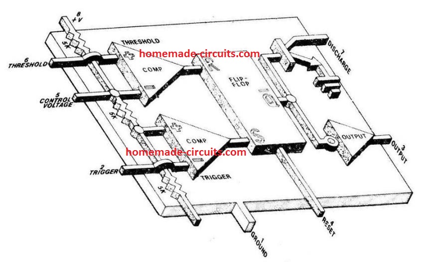
The stage involving the three 5 kohm resistors work like a voltage divider stage which produces 1/3rd voltage level at the non-inverting input of the trigger comparator op amp and a 2/3 voltage division on the inverting input of the threshold comparator op amp.
With these trigger inputs the two op amps control the R/S (reset/set) flip flop stage, which further control the ON/OFF conditions of the complementary output stage and the driver transistor Q6
The output state of the flip flop can be also set by triggering the reset pin 4 of the IC.
How IC 555 Timers Work
When IC 555 is configured in the monostable timer mode, the TRIGGER pin 2 is held at the supply level potential through an external resistor RT.
In this situation, Q6 remains saturated, which keeps the external timing capacitor CD shorted to ground, causing the OUTPUT pin 3 is to be at a low logic or 0 V level.
The standard Timer action of the IC 555 is initiated by introducing a 0 V trigger pulse at pin 2. This 0V pulse being below the 1/3rd level of the DC supply voltage or the Vcc, forces the output of the trigger comparator to change state.
Due to this, the R/S flip-flop also changes its output state, turning off Q6 and driving OUTPUT pin 3 high. With Q6 switching OFF disconnects the short across CD.
This allows the capacitor CD to charge via the timing resistor RD until the voltage across CD reaches 2/3rd supply level or Vcc.
As soon as this happens the R/S flip flop reverts to its previous state, switching ON Q6 and causing a quick discharge of CD. At this instant the output pin 3 returns back to its earlier low state yet again.
And this is how the IC 555 completes a timing cycle.
As per one of the characteristics the IC, once triggered it stops responding to any subsequent triggers, until the timing cycle is completed.
But if one wants to terminate the timing cycle, this can be done at any moment by applying a negative pulse or 0 V to the rest pin 4.
The timing pulse generated at the IC output is mostly in the form of a rectangular wave whose time interval is defined by the magnitudes of R and C.
The formula for calculating this is: tD (time delay) = 1.1 (value of R x value of C) In other words the timing interval produced by IC 555 is directly proportional to the product of R and C.
The following graph shows the plotting of time delay vs. resistance, and capacitance using the above the time delay formula. Here tD is in milliseconds, R is in kilo Ω , and C in μfarads.
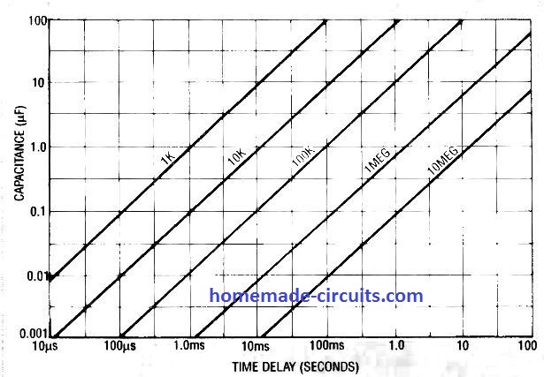
It shows a range of time delay curves and the linearly changing values with respect to the corresponding values of RT and C.
It is possible to set delays ranging from 10 µseconds to 100 µseconds by selecting appropriate values of capacitors from 0.001 µF to 100 µF and resistors from 1 k Ω to 10 meg Ω .
Simple IC 555 Timer Circuits
The first figure below shows how to make a IC 555 timer having a fixed period output. Here it is set to 50 seconds.
It is basically an IC 555 monostable design.
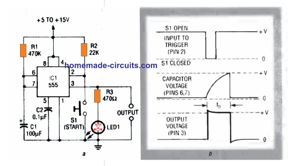
The adjoining figure shows the waveforms obtained across the indicated pinouts of the IC during the switching process.
The actions as described in the waveform image initiates as soon as the TRIGGER pin 2 is grounded with the pressing of momentary START Switch S1.
This instantly causes a rectangular pulse to appear at pin 3 and simultaneously generates an exponential sawtooth at DISCHARGE pin 7.
The time period for which this rectangular pulse remains active is determined by the values of R1, and C1. If R1 is replaced with a variable resistor, this output timing could be set as per user preference.
The LED illumination indicates the ON and OFF switching of the output pin 3 of the IC
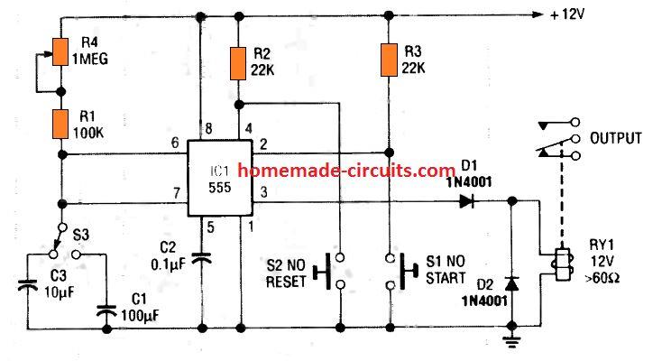
The variable resistor can be in the form of a potentiometer as shown in the following figure 2.
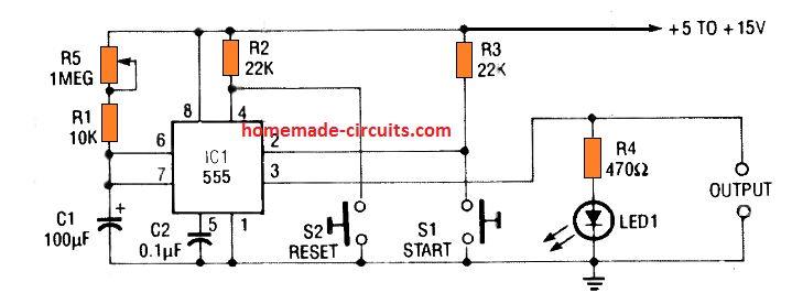
In this design the output can set to produce time periods from 1.1 seconds to 120 seconds through different adjustments of the pot R1.
Notice the series 10K resistor which is very important since it safeguards the IC from burning in case the pot is turned to its lowest value.
The 10 K series resistor also ensures the minimum resistance value required for the correct working of the circuit at the minimum pot setting.
Pressing the switch S1 momentarily enables the IC to start the timing sequence (pin 3 going high and LED turning ON), while pressing S2 reset button allows instant termination or resetting of the timing sequence so that the output pin 3 reverts to its original 0 V situation (LED turning OFF permanently)
The IC 555 allows the use of loads with maximum current specifications of up to 200 mA.
Although these loads are normally non-inductive types, an inductive load like a relay can be also effectively used directly across pin 3 and ground as shown in the following diagrams.
The 3rd figure below we can see that the relay can be wired across pin 3 and ground, and, pin 3 and positive.
Notice the freewheeling diode connected across the relay coil, it is highly recommended for neutralizing the dangerous back emfs from the relay coil during switch OFF instants.
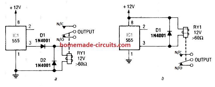
The relay contacts can be wired with an intended load for switching them ON/OFF in response to the set time intervals.
The 4rth circuit diagram shows the standard IC 555 adjustable timer circuit having two sets of timing ranges and an output relay for toggling the desired load.
Although the schematic looks correct, this basic circuit may actually have a few negative aspects.
- First, this design will drain some current continuously, even while the output of the circuit is in the off state.
- Second, since the two capacitors C1, and C3 have a wide tolerance specs, the pot neds to be calibrated with two individual set up scales.
The above discussed flaws can be actually overcome, by configuring the circuit in the following manner. Here we use a DPDT relay for the procedures.
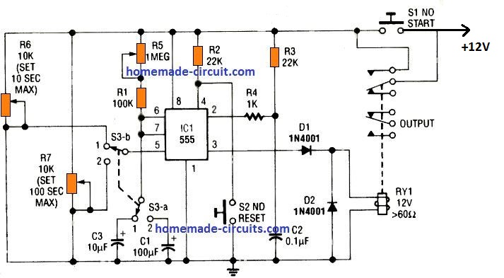
In this 5th IC 555 timer diagram we can see that the relay contacts are joined in parallel with the START switch S1, which are both in the "normally-open" mode, and ensures there's no current drain while the circuit is OFF.
To initiate the timing cycle, S1 is pressed momentarily.
This instantly powers the IC 555. At the onset, C2 can be expected to be fully discharged. Due to this, a negative switch ON trigger is created at pin 2 of the IC, which initiates the timing cycle, and the relay RY1 switches ON.
The relay contacts which are connected in parallel with S1 enables the IC 555 to remain powered even after S2 is released.
When the set time period elapses, the relay is deactivated and its contacts revert to the N/C position disconnecting power from the entire circuit.
The timing delay output of the circuit is basically determined by R1 and potentiometer R5 values, along with the values of either C1 or C2, and depending on the position of the selector switch S3 a.
Having said this, we must also note that the timing is additionally affected by how the potentiometers R6 and R7 are adjusted.
They are switched through the switch S3 b and integrated with the CONTROL voltage pin 5 of the IC.
These potentiometers are introduced to effectively shunt the internal voltage of the IC 555, which might otherwise disturb the output timing of the system.
Due to this enhancement the circuit is now able to function with utmost accuracy even with capacitors having inconsistent tolerance levels.
Furthermore, the feature also allows the circuit to work with a solitary timing scale calibrated to read two individual timing ranges as per the positioning of the selector switch.
For setting up the above accurate IC 555 timer circuit, R5 must be initially adjusted to it maximum range. After this, S3 may be selected to position 1.
Next, adjust R6 to get a 10 second ON timing output scale with some trial and error. Follow the same procedures for the position 2 selection, through the pot R7 for getting an accurate scale of 100 seconds
Timers for car lights
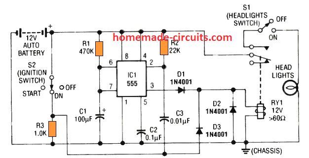
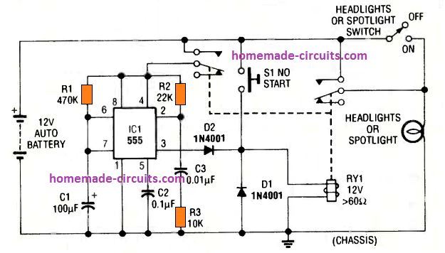
This 6th simple car headlight IC 555 based timer prevents the car headlights from shutting off as soon as the ignition is turned OFF.
Instead, the headlights are allowed to remain illuminated for some preset delay, once the driver locks the car ignition and walks off towards his destination which may be his home or office.
This allows the owner to see the path and enter the destination comfortably with visible illumination from the headlights.
Subsequently, when the delay period elapses the IC 555 circuit switches off the headlights.
How it Works
When the ignition switch S2 is turned ON, the relay RY1 energizes via D3. The relay enables the headlight operations via the upper relay contacts and the switch S1, so that the headlights works normally through S1.
At this point the capacitor C3 associated with pin 2 of the IC remains completely discharged because both its leads are at the positive potential.
However, when the ignition switch S2 is turned OFF, the C3 capacitor is subjected to a ground potential via the relay coil, which suddenly causes a negative trigger to appear at pin 2.
This triggers ON the IC 555 output pin 3, and allows the relay to remain energized even though the ignition is switched OFF.
Depending on the values of the timing components R1 and C1, the relay stays energized keeping the headlights ON (for 50 seconds), until finally the time period elapses and pin 3 of the IC turns OFF de-energizing the relay and the lights.
The circuit does not create any interference with the usual functioning of the headlights while the car is running.
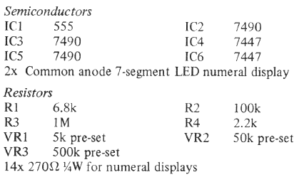
The next 7th timer circuit shown below is also a car headlight timer which is controlled manually instead of the ignition switch.
The circuit utilizes a DPDT relay having two sets of contacts. The IC 555 monostable action is initiated by pressing S1 momentarily. This energizes the relay, and both the contacts move upward and connect with the positive supply.
The right side pair of contacts activates the headlights, while the left side contacts power the IC 555 circuit.
The C3 causes a momentary negative pulse to appear at pin 2 which triggers the counting mode of the IC, and pin 3 becomes high latching ON the relay.
The headlights are now switched ON. Depending on the values of R1 and C1 the pin 3 output keeps the relay and the headlights energized (for 50 seconds in this case), until the C1 charges up to the 2/3rd Vcc, turning pin 3 low, and turning Off the relay and the headlights.
1 Minute Porch Light Timer
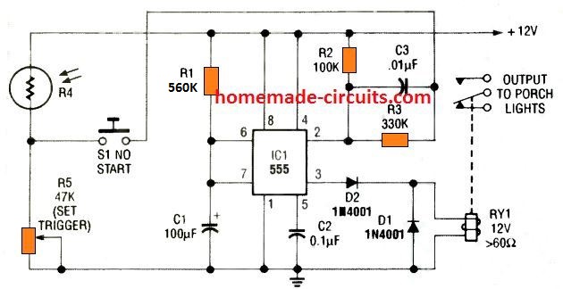
This 8th circuit shows simple porch light timer circuit that can be activated for a minute only during night time. During day time the LDR resistance becomes low which keeps its junction with R5 high.
Due to this, pressing S1 has no effect on pin 2 of the IC. However, when darkness falls, LDR resistance goes infinite, developing an nearly 0 V at the junction of R4 and R5.
In this condition when the switch S1 is pressed, causes a negative trigger at pin 2 of the IC 555, which activates pin 3 to high and also turns ON the relay. The porch light attached with the relay contacts illuminates.
The circuit stays triggered for around 1 minute, until C1 charges to the 2/3rd Vcc. The IC now resets to the turn pin 3 low and de-energizing the relay and switching OFF the porch light.
The switch S1 may be in the form of a small hidden switch near the door handle/hinge, or under the mat which activates when the owner steps on the mat.
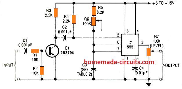
Tachometer Application
A monostable timer circuit using IC 555 can be also effectively implemented for making a tachometer circuit which will provide the user with accurate information regarding the frequency and engine timing.
The incoming frequency from the engine are first converted to well dimensioned square wave through an RC differentiator network and then fed to pin#2 of the monostable.
The differentiator network transforms the leading or trailing edges of the square wave signal into appropriate trigger pulses.
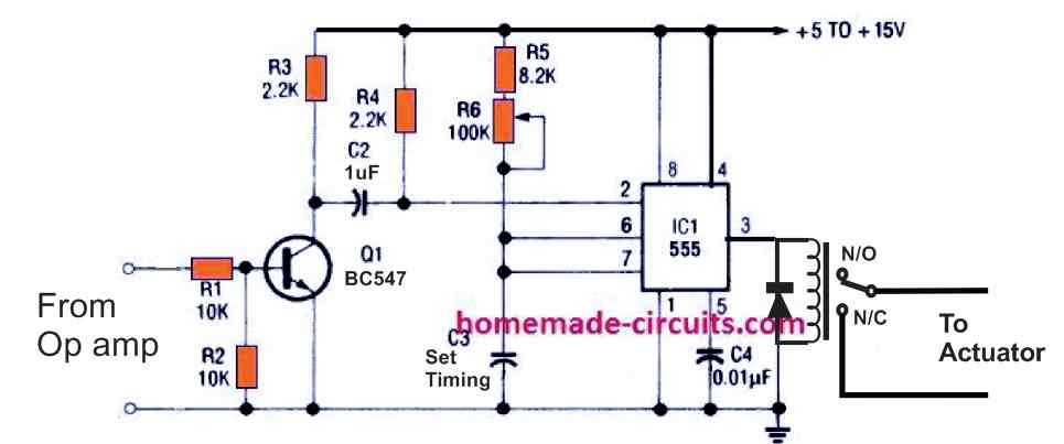
A 9 th practical circuit below shows how an RC network and a transistor converts any input signal with any amplitude into well formed square waves for generating ideal triggering pulses, switching between the full IC Vcc level and ground.
Mains AC Delay Timer
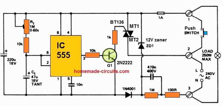
Perfect for an automatic corridor lighting timer, this IC 555 delay timer setup utilizes a momentary action push-button switch with mains rating.
When the switch is pressed, the timer initiates its operation, lasting for a duration precisely equal to 1.1 times the product of R1 and C1.
Once this time elapses, both the load and the entire circuit disconnect simultaneously from mains power.
Conclusion
In all of the circuits presented so far, the 555 functions as a monostable (one-shot) timing period generator. The required trigger signals are fed to TRIGGER pin 2 and a timed pulse at the output pin 3 is delivered.
In all the designs the signal applied at TRIGGER pin 2 are appropriately dimensioned to form a negative edged pulse.
It ensures that the trigger amplitude switches from an "off' level higher than 2/3rd of the supply voltage to an "on" value lower than 1/3rd of the supply level.
Triggering of the IC one shot monostable actually happens when the potential at pin 2 is pulled down to 1/3rd of the supply voltage level.
This requires the trigger pulse width at pin 2 to be higher than 100 nanoseconds but lower than the pulse which is intended to appear at the output pin 3.
This ascertains the elimination of the trigger pulse by the time the set monostable period elapses.


Questions & Answers
Estimado Swagatam
quiero hacer un temporizador pero necesito que el pulso de inicio será largo. no un pulso rápido, es para una máquina que el pulso lo da un switch que queda cerrado para inco del temporizador. si me puedes ayudar te agradecería. saludos
Hey Ricardo, thanks for your interesting question….I think the following circuit might fulfil your requirement:
Dear Swagatam,
I have a diesel genset with an electronic AVR. When I start it up the circuit breakers on the AVR trip every time. On the AVR board there is a low current link. When I start the genset with the link open it produces low voltage AC and then I close the link and It produces 3 phase power just fine. So I need a timer circuit triggered by the start button to delay closing the link for a few seconds, which stays on while the 24volt ign switch is on and drops out when the ign is turned off. Can you help me please .
Thankyou
Thank you Michael,
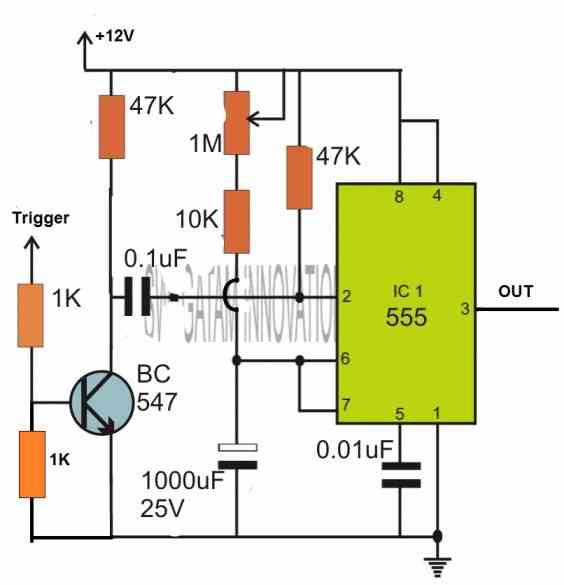
Here is a delay ON circuit you can try for your application:
The R2 side input is given from the start button, the relay contacts can be used for the closing link.
This circuit will work with 24V DC also, just make sure the C2 is rated at minimum 35V.
Hello Swagatam!
I love your emails and the content. I am learning, usually by breaking something, I let the smoke out of a lot of LEDs :^)
I especially like this article about the 555 timer. Have printed it for quick reference.
My circuit that I am working with right now, and would like some help with, is using the 555 to keep a load on for 1 minute after being tripped by a PIR. It is a Halloween display that I have been working on for a while.
I have the PIR set to trip a BC557 that trips the 555 that trips the D880. I am using a 470k resistor between VCC and terminals 6 & 7 of the 555, and a 22k between VCC and terminal 2 of the 555. I have 100 uF cap from terminal 7 to ground and a 1 uF cap between terminal 5 and ground. Terminal 3 is connected to the base of the D880 which controls the ground of the load. The load is connected directly to the 5 VDC power source. Terminal 1 is connected to ground and terminals 4 & 8 are connected to VCC.
The trouble is that when powered, the circuit comes on and does not time out. The 555 gets very warm. When the PIR is disconnected it does not stall the connection. I have tested the PIR/BC557 side and all is functioning as designed. Have tested the D880 and it functions as designed. If the PIR is disconnected and the circuit powered on, no power is transmitted to the load. Yet when the PIR is connected, the circuit sends power to the load and does not time out. If I take the 555 out of the socket (yes I installed a socket due to the trouble) hook up the PIR, power the circuit no power is transmitted to the load even with the PIR connected. Then I can trip the PIR and power is transmitted but does not time out. I have checked and replaced all components except the 1 uF cap, the D880, BC557, and PIR have tested good individually so they have not been replaced either.
Have been over my assembly several times. I am learning so my work has not been without mistakes. I do believe I have my mistakes corrected, yet the problem persists. The circuit works on my breadboard, my problem is on my perf board.
I know I might not have given good information here, yet would like help with this as Halloween is a week away, it would be great to have it working in time.
A huge thank you for the help in the past and for anything you are willing to help with on this one.
Hope your animals are all healthy and happy.
Bill
Hi Swagatam,
My first thought in this process was a simple circuit as you describe in the link. Yet the PIR sensors that I have on hand are the inexpensive Chinese versions (HW-740 is the identifying mark) that do not have any type of adjustments and only keep the circuit active for 3 seconds. I attempted to add an RC delay to the configuration. That proved fruitless and did not add any delay with multiple variations of capacitor and resistor values. That lead me to using the 555. It proved good with 1 LED as a test, when more load was added it started to fail. Thus adding the D880 for the added load.
It all proves good on the breadboard. Once duplicated on a perf board it has the before mentioned issues.
I have at present 3 items for a load. First are 2 styrofoam skulls with red LED eyes. One has a simple flashing circuit comprised of 1 BC547, 1 BC557, 1 resistor 470k, and 1 capacitor 10 uF, the other skull has 2 red LED’s for eyes that are connected to an Arduino Pro Mini and running a fade in out Sketch, and the third is a plastic skeleton Scorpion that has 2 yellow LED’s for eyes and 3 red LED’s one each in the claws and tail. the eyes are running by 2 555 timers that cause them to flash 4 times, delay 1 second and repeat, the red LED’s are run by another 555 that causes them to fade in and out. All the LED’s are in parallel, thus a higher current demand.
So, could you shed some light on adding a delay to the simple PIR circuit to give it an on time of around 50 – 60 seconds? Plus handle the load? I would also like to add lightning simulation to my display. I have Arduino available and some RGBW addressable LED strip. Any suggestions?
Thank again for being here to help, and keep up the emails, I enjoy them very much.
Bill
Hello Swagatam,
Looking at the 555 timer circuit you have suggested, my concern is that you show the power supply at 12 volts. This is too much for the PIR and I want to power the entire project with 1 power supply (a 5 v/2 a USB charger). Will try to power it all with my USB charger, hope it is enough. Would I need to adjust resistors to compensate? (in the case it does not function).
Thanks again,
Bill
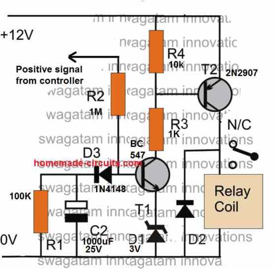
No problem Bill, you can use 5V also without any changes in the design, it should still work as is.
No problem Bill,
You can try the following configuration and it will do the job for your perfectly:
You can adjust the 1M preset to adjust the output delay for the lamps.
For the Arduino lighting display, you can probably try the concept explained in the following article:
https://www.homemade-circuits.com/8-channel-lighting-sequence-generator-for-christmas-diwali-decoration/
Please let me know how it goes…
Hello Swagatam,
I was able to complete the power board in time, though it only powered 1 item on the timer, and the other 2 directly from the source. Did not have time to rework my board for anything further.
I did find that using a Darlington Pair would run 2 of the items as designed. Did not experiment with a Darlington Trio for all 3 of the items. My Scorpion that used the 3 555 timers to flash LEDs at different patterns would not function as designed if another of the items were in the timer circuit. Did not test for current draw/voltage drop in the circuit.
Perhaps I will do some further testing and development after the first of the year with the items from my display. I would like to add a sound and lightning effect. Have DF Player MP3-TF-16P modules, have not done much with them so far though.
I have learned a good bit with this round in this project and had a good time with it (especially when things started to come together and work). I realize there is a learning curve, yet it can be frustrating to figure out what is not doing what it is supposed to. But that is where one gains experience :^)
Thank you again,
Bill
Thanks for the update Bill,
I am glad you could complete the power board and having fun with these electronics experiments and also getting a chance to learn more. Yes there will be a learning curve on this field, and I am sure you will be able to master it fast.
Please let me know if you face any issues with any of the circuits, I am always happy to help!
Hello Swagatam,
I constructed the circuit you suggested using the 555 timer. However the signal output from my PIR is too weak to get through the 1k resistor. After working with the circuit for a while, I found that removing the 1k resistors in the circuit between the PIR and transistor would allow the PIR to trip the transistor. Then reducing the 220 uF capacitor to 47 uF gave me a better range with the variable resistor (brought my time max to about 45 seconds). I also found that my display items do not function well when connected through the delay circuit together. When just 1 is connected it functions as designed. For now will use just 1 on delay, the others will remain on.
Now to construct it on a perf board…
Thanks again,
Bill
Thanks Bill, sounds good,
However a base resistor for the BC547 is required for safety. You can reduce the upper 1K base resistor value for the BC547 to maybe 100 ohms, but make sure to connect this resistor.
Let me know if you face any further problems with the circuit…
Hello Swagatam,
I have experimented with the RC circuit to find the short fall in my project.
The PIR units that I have are small, cheap, non-adjustable (no pot on the board) and have a very low output of 2.9 v/ 0.1 mA. Therefore adding the RC circuit drops the voltage to 0.6 v and will not cause the BC547 to complete the circuit.
That was why my progression took me to the 555 for the delay. I will give the circuit you provided a try on the breadboard today (have not figured out why my iteration worked on the breadboard and not on a perf board :^/ ).
I had been looking for an email to alert of your response… did not get one.
Thank you again, your responses are always welcome here,
Bill
Hi Bill,
yes, in that case the RC would further reduce the voltage and prevent the output sections from working properly.
Are you getting the email alerts now?
Yes, email alerts are getting through.
:^)
OK, great, thanks for the update!
Thanks Bill for the detailed explanation.
I guess you won’t need a 555 IC for the timer action, because the PIR itself has a built-in timer which will keep the load ON for the desired amount of time.
I would recommend you to try the first circuit from the following article, and check how it works. If it works good, then we can further upgrade it in whichever manner we like…
Please let me know if you have any further doubts regarding the circuit:
https://www.homemade-circuits.com/pir-controlled-led-driver-circuit/
Hello Swagatam,
is there any way I can use a low power cmos 555 to make a power-up one shot monostable circuit? eg. a single LED lights up when power applied (about 3.7v) and goes off after about 2 seconds but is not re-triggered until power is turned off and turned back on again.
Your help would very much be appreciated!
Kindest Regards
Hello John,
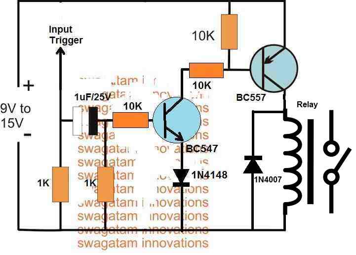
You can try the following design for getting the required results. The relay can be replaced with the LED/resistor and the “input trigger” may be connected with the positive DC supply:
Thank you. I will try it
Thank you very much for your quick response, I will simulate it in the pcb wizard
OK, no problem…
By the way, it must be between 5 to 10 minutes. Something simple like the first circuit..
https://www.homemade-circuits.com/simple-delay-timer-circuits-explained/
OK, then my previously suggested design will be alright for you.
Hello good afternoon, my name is Carlos and I am a faithful follower of the website. I’m looking for a simple timer circuit that starts when powered… Without a pushbutton… Thank you very much.
Thank you Carlos, you can try the following circuit, please ignore the red wire, it is not relevant for your application:
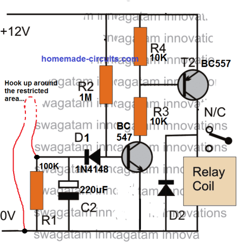
However this is not a long duration timer….it’s maximum delay could be around 30 minutes depending upon the values of R2 and C2
In the 2nd circuit the start and reset have the same outcome. reset also start the timer and not stop timing.
When S1 is pressed and the timing initiates, pressing S2 will stop the timing in the middle and reset the circuit back to it original standby condition.
Please can I have circuit diagram of 1minute on 30minutes off timer using 556 timer ICe
I don’t have it at this time, if possible I will try to design it…
Good afternoon Swagatam
I am really enjoying your web site, and yet again I would be extremely grateful if you could
help me with your expertise, the above circuit you helped me with, works just fine, but for one problem, after the 555 times out the next cycle starts before the comparator has time to clear, so is there a way of introducing a small delay
(a few hundred milli seconds) prior to your start pulse transistor to allow comparator to
clear, or are we into cascading timers?
Many thanks in advance
Regards
Thank you Derek, Glad I could help!
Do you want the Q1 BC547 to start with a slight delay? You can do it by replacing R2 (10K) with a 100uF capacitor
Hi Swagatam
Thank you very much for your fast response, I have implemented your suggestion and everything is now working as designed, the only thing I have changed is the value of the cap from 100uF to 22uF as I only require a few milliseconds
Once again many thanks
Regards
That’s great Derek, Glad it is solved now.
Hi
With regards to your 9th practical timer circuit (transistor), is the value of C2 (0.001pF) correct? as I cannot source one. and one other question what is the purpose of the 8.2K resister prior to the pot
Many thanks in advance
Hi, that’s seems to be a printing mistake. It is supposed to be 0.001uF, however you can use a 0.1uF also. The 8.2k ensures that the IC 555 does not get damaged if accidentally the pot is rotated fully towards the the positive supply side. You can use any resistor between 4k7 and 10K instead of 8.2K
Hi, thank you for your fast response,
I am not sure if this is right design for my needs, maybe you could possibly help me if tell you my requirements,
The input to the TLC555 is feed from the output of a MCP6542 comparator (which is positive and active until the 555 times out) The time I require is variable between 1 and 15 seconds, also the output of 555 needs to be positive, is this something you help me with
Many thanks in advance
By the way this is a fantastic web site
I can help you but I could not understand the requirement correctly. You mean to say the comparator output switches ON the 555 input so that the output of the 555 remains ON for the set amount of time then it switches OFF. As soon as the 555 output switches OFF it also switches OFF the comparator? But how does initially the comparator switch ON, because initially the 555 output will be switched OFF so the comparator will be also remains switched Off, so how the comparator is supposed to switch ON initially for feeding the 555 circuit?
Hi sorry for the confusion I have not given you the complete picture, the timer is just a one part of the system,
when the timer times out it initiates the next part of the sequence so the comparator resets and carries on until the detection, this is repetitive system
hope I have clarify d this for you
No problem, can you please tell in a step wise manner what stages you require in the design and how the stages need to function?
Hi,
I will give a little bit more info about the system, the main part is a linear actuator moved by a stepper motor with a Bourns AMM20B position sensor mounted on the shaft giving 0-5vdc feedback of position
The comparator is configured as window comparator with high and low inputs set via two slide pots
so in essence they form 2 electronically moving limit switches, on the threshold at each end the actuator reverses
The output from the comparator is cmos push pull +5vdc, but opto couplers can be fitted if this helps your design.
a) so when either threshold are meet the comparator goes high +5vdc this is when we use this to start the timer the output from the comparator goes to the input of the 555
b) when the timer starts, the output from the 555 goes high (this is used to stop actuator moving ) and because it is not moving the input to the 555 will still be high
c)on timing completion the output of the 555 goes low this will start the actuator and clear the input to the 555
My only concern is although the system is very fast, starting the actuator at the end of timing may not clear the input unless some thing could be put around it
d) the above procedure happens at each end of the stoke and the timings may be different so we will to have two sets of timers
e) Timing range variable 1-15 seconds
I hope this makes some sort of sense
If there is any more information you require please get in touch
Best regards
OK, I have understood the basic functions of the required design. I think the following monostable should do the job for you. Let me know if you have any further questions
Hi, thanks for your answers
I have a further query, regarding the value of C2 in the latest drawing you supplied me it states 1uF is this correct? as in a previous communication you said it could be either 0.001uF or 0.1uF, or is that value specific to my needs.
sorry to be a pain
Regards
Yes, I have changed it to 1uF, because in my experiments I have seen that a slightly larger value capacitor at pin#2 of the IC enables faster and reliable switching of the IC, which sometimes does not happen with smaller value capacitors such as 0.1uF or 0.001uF.
Thank you for your speedy response,
I could could not find your alternative design “alt=”555 monostable with relay ON/OFF timing” />'” I get an “ERROR 404” If you could point me to that
I am going build this circuit and try it out, I am assuming by your diagram that the output of the 555 is positive, because of the speed of the system I will not be using a relay as they can be too slow and subject to bounce, instead I am going to try using a CD4066 to interface with the controller.
This looks to be a good design, many thanks
Regards
You are most welcome!
Here’s the diagram link which I had referred to you:
You can remove the relay and use a 4066 IC. Yes the IC 555 output will be positive in response to the positive trigger input from the op amp.
I’ve studied the above 555 timer circuits (have even built the 10 led tacho circuit with 555 timer you published) and I’m now trying to work out how to adjust the npn magnetic sensor input of a cheap Aliexpress tacho display so that it will show speed (kmph) on the display (it’s small and will fit nicely on my self built monster) instead of rpm.
Can you please push me in the right direction?
I tried to investigate the issue you are facing, but unfortunately I failed to figure out a proper solution.