An electronic dog whistle is a device that generates ultrasonic sound waves and is used for training dogs and for controlling excessive barking habit. Because dogs and domestic cats can hear ultrasonic frequencies, humans cannot, this dog whistle device is employed to train these animals. It is also sometimes known as a silent whistle or Galton's whistle.
Francis Galton invented this device in the year 1876, and he discusses this in his book "Inquiries into Human Faculty and Its Development", where he explains his investigations to see what range of frequencies different animals, such as a house cat, could hear.
Frequencies that Cats and Dogs can Hear
For children, the maximum limit of the human hearing range is around 20 kilohertz (kHz), whereas for middle-aged adults it is 15-17 kHz.
While a cat can hear up to 64 kHz, a dog can hear up to roughly 45 kHz. It is believed that the wild ancestors of cats and dogs developed this increased hearing range in order to detect the high-frequency sounds emitted by their primary food, tiny rodents.
Typically dog whistles feature frequencies between 23 and 54 kHz, which puts them above the range of human hearing, however some can be adjusted to become more audible.
How Mechanical Dog Whistles Work
A dog whistle just sounds like a soft hissing to human hearing. The benefit of the dog whistle is that it may be used to train or instruct animals without upsetting adjacent neighbors because it doesn't generate the loud, piercing noise that a regular whistle would.
The normal mechanical dog whistles include movable sliders that allow for active frequency adjustment. The whistle could be used by instructors to either get a dog's attention or to cause them discomfort in order to change their habits.
Electronic Dog Whistle
In addition to whistles which are operated by mouth, there are also electronic whistles that use piezoelectric emitters to produce ultrasonic sound.
In an effort to reduce frequent barking, the electronic version is typically used in conjunction with circuits that detect barking. This type of whistle may also be utilized for physics experiments that require ultrasonic frequencies, as well as for applications determining a person's hearing range.
The electronic dog whistle circuit discussed in the article is a fascinating and entertaining equipment that you may use to confuse, annoy, or perhaps assist in training your four-legged, tail-wagging buddies. However, I can't promise that your Dog would accept the training aspect.
Our closest friends easily outperform us in the senses of hearing and scent. Fido's hearing is still excellent, just about the point where ours begins to deteriorate.
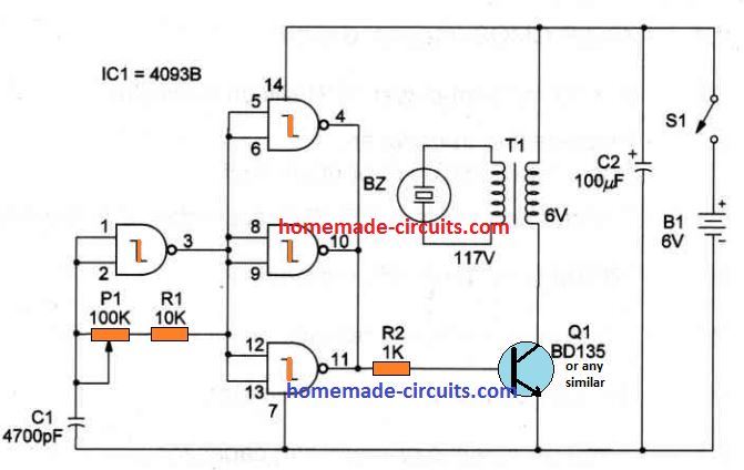
Circuit Description
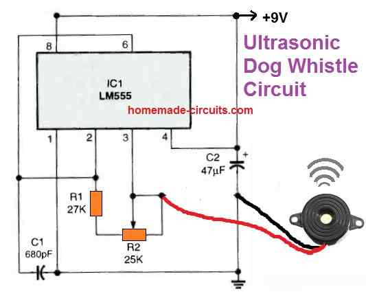
The electronic dog whistle circuit displayed above may produce ultrasonic frequencies between 15 and 45 kHz.
In order to experiment with training your dog, the lower frequency end of the spectrum is most recommended.
Since the high-frequency output can be quite irritating for your pet's ears, you should limit their exposure to it as much as possible.
A 555 integrated circuit (IC) powers the ultrasonic generator. The 555 IC is wired into a square-wave oscillator stage that has an adjustable frequency, and its pin 3 output is used to drive a piezo speaker that may be 27 mm in diameter.
The 27 mm piezo element could be purchased as a ready made unit in the following form:
R2, which is a 25K potentiometer, adjusts the oscillator's frequency to the appropriate value. The circuit is powered by a typical 9-volt transistor battery.
Reference: Wikipedia
Questions & Answers
I love your circuit design for dog whistles, however, what I am looking for is a recorder that loops thru all the range, say 10 seconds each. Passes thru an amplifier, so it reaches across the cove, then have a large enough speaker with enough power to extend the range. Any ideas?
Thank you and glad you liked the post. You can do this, create a sequential output generator (at 10 seconds rate) using IC 4017 and IC 555, then connect separate oscillators across the 10 outputs of the 4017, so that it generates 10 different frequencies in a sequential manner and repeats itself.
The outputs of these frequencies could be connected with an amplifier for further amplification.
How far can it be heard? Would the electronic whistle, silent whistle or Galton’s whistle be heard into neighbors yard? I also have neighbors with barking dogs. ☺️ thanks
According to me it should be audible to the dogs upto 20 meter range
Very interesting site, I was wondering if there is a way to activate my neighbors dog perimeter collar, it is wireless and has a transmitter located in their garage, those dogs stand at the edge of their property and bark constantly, talking with the owners has gone no where, Thanks for any input
To activate the receiver on the collar of the dog, you may have to transmit the whistle frequency through a transmitter circuit. However, before this we must know at what carrier frequency the collar receiver is designed to operate? Or may be we can try transmitting the whistle frequency on random carrier frequencies and keep checking which frequency locks in with the dog receiver….this process can be a lot difficult and time consuming.