In this post I have explained about a simple Hi-Fi balanced microphone preamplifier circuit and also evaluate the calculations, specifications of the design through formulas.
What is a Balanced Preamplifier
A "balanced" amplifier or differential amplifier possesses not one but two distinct inputs and only the difference amongst these inputs is actually amplified.
To elucidate just how this performs please see the diagram that indicates a basic version of a balanced microphone preamplifier circuit. To help make the calculation less difficult we are going to cut down the gain to 9 simply by doing Rl = R4 = and R5 = Rl l = 9.
Circuit Diagram
Typically the units aren't critical. just the proportions are. We are going to commence the justification by exploring the situation wherein input with R1 is at 0V and input with R4 is at + l00mV.
How the Circuits Works
An perfect amplifier will do a couple of stuffs - it will not take virtually any current into the input pins and it keep the output unaffected regardless of any voltage variations at the input pins.
We therefore will need to have 100mV through R4 and therefore a voltage of 900mV around R11 (it possesses 9 times the resistance and the exact same current like R4). This offers us a gain of nine. The output is for that reason -900mV. In the circumstance any time point A reaches 0V and point B is in +100mV. point D is going to be at
VB x R5/(R1 + R9) = 90mV
As a result point C will in addition be at +90mV. The voltage around R4 will probably be 90mV and voltage around Rl is going to be 810mV (9 x 90mV).
This implies the output voltage ought to be +900mV. Also this is with gain of nine. Observe even so that the polarity (or phase) is not equal. At this point imagine both inputs are at say + 1V, point D will probably be at +900mV and thus will point C.
The voltage through R4 is l00mV and R11 900mV This provides an output voltage of (1V The common signal is just not amplified by any means In case however, one input (B) reaches IV and the other (A) was at l.0lV the difference is amplified and the output will probably be -lV.
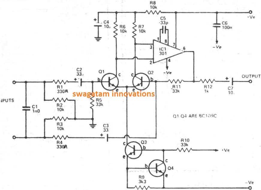
Returning to the specific circuit, we have employed an LM301A with a pair of low-noise transistors in the front stage.
These transistors come with a constant current through Q3 and Q4. A constant current is necessary because enables the inputs to increase and down without transforming the voltage around R6 or R7
The resistor R2 and R3 relate the inputs to UV are usually high enough never to impact the functioning in the slightest
Parts List for Balanced Microphone Pre-Amplifier Circuit
- R1, R4 = 330
- R2,R3, R6, R7, R8 = 10K
- R5 = 33K
- R9 = 3K3
- R10, R11 = 33K
- R12 = 1K
- C1 = 1nF C2,
- C3 = 33uF/25V
- C4, C7 = 10uF/25V
- C5 = 33pF
- C6 = 100nF
- Q1, Q4 = BC109C
- IC1 = LM301A
Technical Specifications:
Frequency Response: 10Hz - 20kHz (<5V output) +0/ -3dB
Gain: 40dB
Equivalent Input Noise: -123dB (0.5uV)
Distortion: 0.05%, 300mV - 5V output, 100Hz - 10kHz
Max Input Voltage: 100mV
Common Mode Rejection Ratio: 60dB
Maximum Common Mode Signal: 3V
Another Design using IC LM833
The LM833, a dual low-noise, high-performance op-amp from National Semiconductors, serves as a superb choice for constructing a balanced microphone preamplifier.
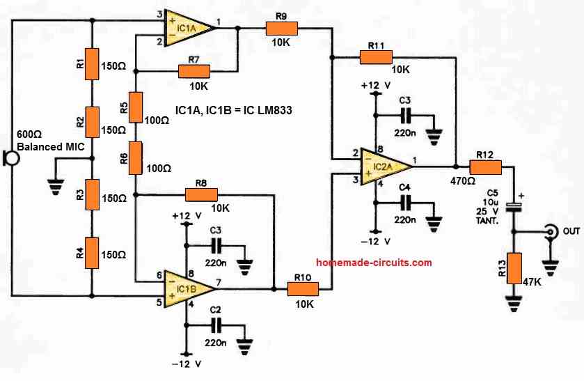
This circuit is designed to work seamlessly with standard 600 Ohm balanced microphones and delivers an approximate gain of 40 dB.
For the output stage, one op-amp from another LM833 is utilized, specifically IC2A. To safeguard IC2A against output shorts, R12 is incorporated into the design. To ensure minimal noise, it is advisable to use metal film resistors

Questions & Answers
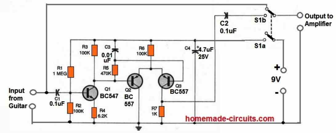
Dear Sir I need a simple circuit purpose of I will speak to the microphone and It will be connected to the Amplifier. I already Have amplifier need only Microphone circuit. Thank You
Hi Jobayer, you can try the following circuit:
Hi Swag, sorry to contact you this way but the email address I have admin@homemade-circuits is not working, whats best way to send you a question?
Hi Pete, you can express your thoughts through this commenting platform, it is the best way to reach me and solve the queries quickly….I have cancelled the mentioned email ID due to its inadequate features.