In this article I have explained a step by step tutorial regarding designing your own homemade basic induction heater circuit, which can be also used as an induction cooktop.
Basic Induction Heater Concept
You might have come across many DIY induction heater circuits online but nobody seem to have addressed the crucial secret behind implementing a perfect and a successful induction heater design. Before knowing this secret it would be important to know the basic working concept of an induction heater.
An induction heater is actually an extremely "inefficient" form of electrical transformer, and this inefficiency becomes its main advantageous feature.
We know that in an electrical transformer the core needs to be compatible with the induced frequency, and when there's an incompatibility between frequency and the core material in a transformer, it results in the generation of heat.
Fundamentally an iron cored transformer will require a lower range of frequency around 50 to 100Hz, and as this frequency is increased the core may shown a tendency of getting hotter proportionately. That implies, if the frequency is increased to a much higher level may be over 100kHz would result in the generation of extreme heat within the core.
Yes, this is exactly what happens with an induction heater system where the cooktop acts like the core and therefore is made up of iron material. And the induction coil is subjected to a high frequency, together this results in the generation of a proportionately intense amount of heat on the vessel. Since the frequency is optimized at significantly high level ensures a maximum possible heat on the metal.
Now let's proceed and learn the important aspects that may be required for designing a successful and technically correct Induction heater circuit. The following details have explained this:
What you will Need
The two bare basic things required for building any induction cookware are:
1) A bifilar coil.
2) An adjustable frequency generator circuit
I have already discussed a few induction heater circuits in this website, you can read them below:
Solar Induction Heater Circuit
Induction Heater Circuit Using IGBT
Simple Induction Heater Circuit - Hot Plate Cooker Circuit
Small Induction Heater Circuit for School Project
All the above links have the above two things in common, that is they have a work coil and a driver oscillator stage.
Designing the Work Coil
For designing an induction cookware, the work coil is supposed to be flat in nature, therefore it must be bifilar type with its configuration, as shown below:
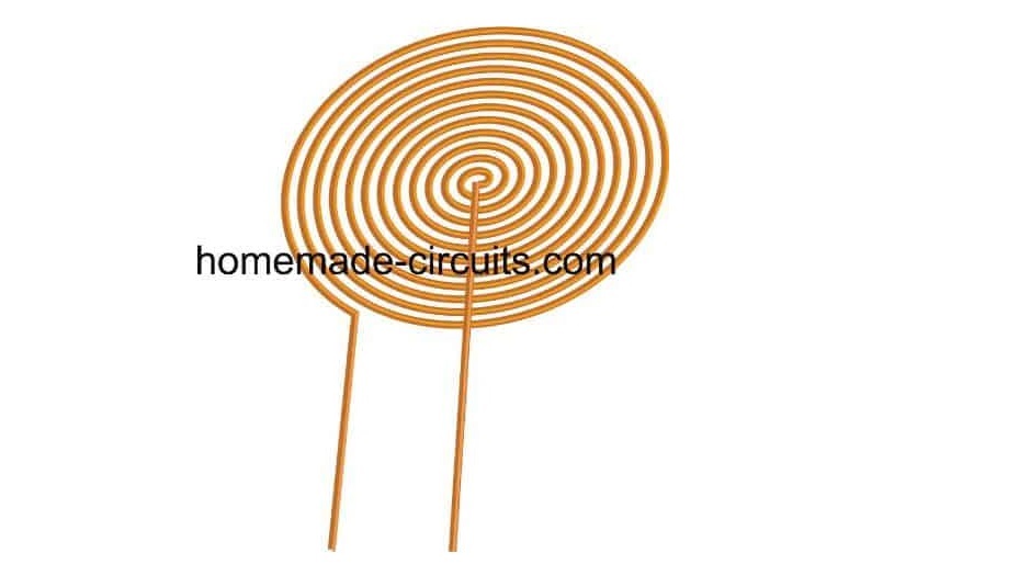
The bifilar coil type design shown above can be effectively implemented for making your homemade induction cookware.
For optimum response and low heat generation within the coil make sure the wire of the bifilar coil is made using many thin strands of copper instead of a single solid wire.
Thus, this becomes the work coil of the cookware, now the ends of this coil simply needs to be integrated with a matching capacitor and a compatible frequency driver network, as shown in the following figure:
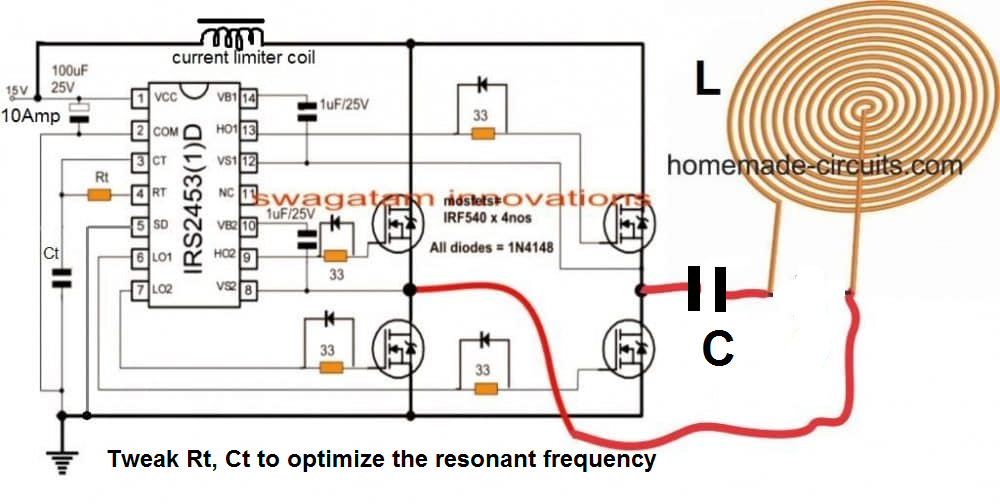
Parts List
- 33 Ohms 1/4 watt 5% = 4 nos
- Rt = To be determined by experimentation.
- 1uF/25V Electrolytic = 2 nos
- 100uF/25V Electrolytic = 1 no
- Ct and C = To be determined by experimentation.
- 1N4148 diodes = 4 nos
- MOSFETs IRF540 = 4 nos
- IC IRS2453 = 1 no
- Work Coil = As shown in the diagram. Diameter will need to be experimented.
- Current limiting Inductor = Can be between 1 mH to 5 mH. Again this one will need to be experimented.
- While experimenting the unknown components make sure to use a 12 V, 50 watt watt bulb in series with the DC supply line, to avoid accidental damage to the MOSFETs.
Designing the H-Bridge Series Resonant Driver Circuit
So far the information should have enlightened you regarding how to configure a simple induction cookware or an induction cooktop design, however the most critical part of the design is how to resonate the coil capacitor network (the tank circuit) into the most optimal range so that the circuit works at the most efficient level.
Enabling the coil/capacitor tank circuit (LC circuit) to operate at their resonance level requires the inductance of the coil and the capacitance of the capacitor to be matched perfectly.
This can happen only when the reactance of both the counterparts are identical, that is the reactance of the coil (inductor) as well as the capacitor are approximately the same.
Once this is fixed you can expect the tank circuit to operate at its natural frequency and the LC network reaching the resonance point. This is called a perfectly tuned LC circuit.
This concludes the basic induction heater circuit designing procedures
You may be wondering regarding what is resonance of an LC circuit.?? And how this may be calculated quickly for completing a specific induction heater design? We will comprehensively discuss this in the following sections.
The above paragraphs explained the fundamental secrets behind developing a low cost yet effective induction cooktop at home, in the following descriptions we will see how this can be implemented by specifically calculating its crucial parameters such the resonance of its tuned LC circuit and the correct dimension of the coil wire for ensuring an optimal current handling capacity.
What is Resonance in Induction Heater LC Circuit
When the capacitor within a tuned LC circuit is momentarily charged, the capacitor tries to discharge and dump the accumulated charge over the coil, the coil accepts the charge and stores the charge in the form of magnetic field. But as soon as the capacitor has discharged in the process, the coil develops an almost equivalent amount of charge in the form of magnetic field and it now tries to force this back inside the capacitor, although with an opposite polarity.
Image courtesy:
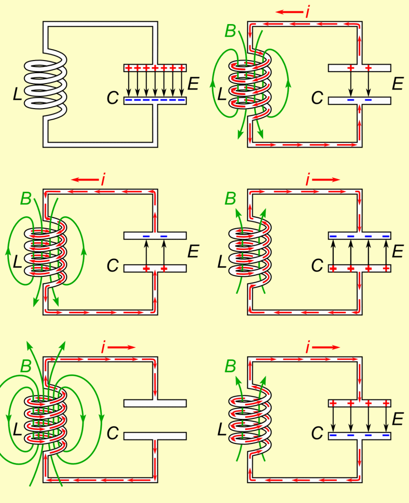
The capacitor is again forced to charge but this time in the opposite direction, and as soon as it's fully charged, it yet again tries to empty itself across the coil, and this results in a back and forth sharing of charge in the form of an oscillating current across the LC network.
The frequency of this oscillating current becomes the resonance frequency of the tuned LC circuit.
However due to inherent losses the above oscillations eventually die out in the course of time, and the frequency, the charge all come to an end after sometime.
But if the frequency is allowed to sustain through an external frequency input, tuned at the same resonance level, then that could ensure a permanent resonance effect being induced across the LC circuit.
At resonance frequency we can expect the amplitude of the voltage oscillating across the LC circuit to be at the maximum level, resulting in the most efficient induction.
Therefore we can imply that, to implement a perfect resonance within an LC network for an induction heater design we need to ensure the following crucial parameters:
1) A tuned LC circuit
2) And a matching frequency to sustain the LC circuit resonance.
This can be calculated using the following simple formula:
F = 1 ÷ 2π x √LC
where L is in Henry and C is in Farad
If you don't want to go through the hassles of calculating the resonance of the coil LC tank through formula, a much simpler option could be to use the following software:
LC Resonant Frequency Calculator
Or you may also build this Grid dip meter for identifying and setting the resonance frequency.
Once the resonance frequency is identified, it's time to set the full-bridge IC with this resonance frequency by suitably selecting the Rt, and Ct timing components. This may be done by some trial and error through practical measurements, or through the following formula:
The following formula can be used for calculating the values of Rt/Ct:
f = 1/1.453 x Rt x Ct where Rt is in Ohms and Ct in Farads.
Using Series Resonance
The induction heater concept discussed in this post uses a series resonant circuit.
When a series resonant LC circuit is employed, we have inductor an (L) and a capacitor (C) connected in series, as shown in the following diagram.
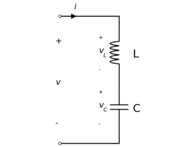
The total voltage V applied across the series LC will be the sum of the voltage across the inductor L and the voltage across the capacitor C. The current flowing through the system will be equal to the current that's flowing through the L and the C components.
V = VL + VC
I = IL = IC
The frequency of the applied voltage affects the reactances of the inductor and the capacitor. As frequency is increased from a minimum value to a higher value, the inductive reactance XL of the inductor will proportionately increase, but XC which is the capacitive reactance will decrease.
However, while the frequency is being increased there will be a particular instance or threshold when the magnitudes of the inductive reactance and the capacitive reactance will be just equal. This instance will be the resonant point of the series LC, and the frequency can be set as the resonant frequency.
Therefore, in a series resonant circuit, the resonance will occur when
XL = XC
or, ωL = 1 / ωC
where ω = angular frequency.
Evaluating the value of ω gives us:
ω = ωo = 1 / √ LC, which is defined as the resonant angular frequency.
Substituting this in the previous equation and also converting the angular frequency (in radians per second) into frequency (Hz), we finally get:
fo = ωo / 2π = 1 / 2π√ LC
fo = 1 / 2π√ LC
Calculating Wire Size for Induction Heater Work Coil
Once you have calculated the optimized values of L and C for the tank circuit of the induction heater and evaluated the exact compatible frequency for the driver circuit, it's time to calculate and fix the current handling capacity of the work coil and the capacitor.
Since the current involved within an induction heater design could be substantially large, this parameter cannot be ignored and must be correctly assigned to the LC circuit.
Using formulas for calculating wire sizes for an Induction wire size may be a little difficult especially for the newcomers, and that's exactly why a special software for the same has been enabled in this site, which any interested hobbyist can use to dimension the right size wire for your induction cooktop circuit.



Questions & Answers
Hi Iam from Ecuador my name is Paul Cardenas Gordon.
I came to your website because I am looking for a magnetic induction circuit. I must thank you for having found several options. You can tell me which design I can adapt to get a power of 1kw maximum output.
And how could I do to vary the output power.
I do not study electronics, I study mechanics but I am struggling to understand the circuit.
Thank you for visiting my site Paul!
You can try the following design
https://www.homemade-circuits.com/2017/01/induction-heater-circuit-for-labs-and.html
in this circuit you can limit or change the max power output by appropriately calculating Rx value.
But please remember that this concept is suitable only for experts in the field of electronics, and is not recommended for any newcomer, therefore make sure that you have an expert electronic engineer with you while constructing and testing this circuit.
how to get value of Rt and Ct thank you sir !!!
It is explained in this post
https://www.homemade-circuits.com/2014/01/simplest-full-bridge-inverter-circuit.html
Dear Mr. Swagatam:
I am not a new comer , as i have been working on electronics over 30 years but mostly practical and rarely theorycal so I need your help with making this circuit. as a matter of fact i have made it and works, however with a 300 watt lamp in series and the lamp illuminates so brightly and I have just little heat in the metal inside the coil. as i have burnt out a few expensive IGBTs , I fear to use more powerful lamp. the 4.7 volume has been regulated so precisely. however, the coil i have used is 9 centimeters diameter(for i need this size of the coil) and 4 turns with 4.5 millimeters thickness of the wire. the caps are almost 2.3 uf. Do you think i have to make some changes in the coil or it could be OK?
meanwhile, as the wider a coil , the more useful the circuit could be, i want persistently to use it. please tell me:
1- is the heat OK with the 300 watt lamp?
2_ by what i mentioned can I use more powerful lamps? or i have make changes in the coil?
thank a lot \
Saeed Mahdavi Asl
Dear Saeed, If your 300 watt bulb is illuminating brightly, then it is not good. Your circuit might not be working correctly
At resonance your lamp must have minimum illumination and the load must have maximum heat.
Were your able to achieve the correct resonance for the design??
It has to be done by attaching a magnetic plate with the coil, and then tweaking the frequency until the heat maximizes and the lamp illumination minimizes.
By the way did you connect the SD pin of the IC to ground? Otherwise the system will not initiate.
Dear Swagatam:
I have just LITTLE heat although the 4.7 k volume has been adjusted as precisely as possible but still the 300 w lamp is illuminating so brightly . on the other hand ,
i cant find the Sd pin of the IC although checked with the datasheet.
the circuits has been built exactly in conformity with the plan introduced by you
please tell me:
1- what pin you mean by SD?
2- if the coil is OK. it is 4 turns of 4.5 mm wire with 9 mm diameter.
by the way the only thing to adjust is the volume, so i dont have any more idea of how to regulate the circuit. i have used the shortest wires and four ferittes at the tip of the wires connected to the bases of IGBts.
the last connection points of the caps have been connected to the coil and with thick wires.to me everything is ok but unfortunately the IGBTs will blow out if i use more wattage lamp. for example i lost three of them and one IC today when i used a 800 watt lamp.
please guide me by telling
if the coil is OK and what pin you meant by SD.
your Sincerely Saeed
Saeed, The SD pin is pin#5 of the IC, just under the Rt pin…. it is clearly visible in the diagram, I am wondering how you could not find it?
By the way where is 4.7K, are you referring to the Rt resistor selected by you as 4.7k??
Please try using the following formula for selecting the coil, capacitor and frequency parameters
F = 1 ÷ 2π x √LC
F can be determined by adjusting Rt/Ct, C can be randomly selected, once F and C are determined L can be calculated by solving the above formula.
Frequency will need to be confirmed using a frequency METER across the output pins of the IC.
As long as resonance is not achieved the circuit will not work optimally, and you will keep losing mosfets and IGBTs
Alternatively you can go with the existing set up, connect an arbitrarily selected Capacitor for “C” and Ct, and then tweak Rt until you find the heat to be maximum and illumination on the 300 watt bulb minimum.
Remember you must do the above by attaching an iron plate with the coil, if you keep the coil air-cored then the circuit will never work, I have already cautioned about this in my previous comment.
try a 7 turns coil, this will allow a lower frequency and stable operations
Dear swagtam:
here i should add that my problem is concerning the induction heater with 4 IGBTs and the coils with air core.
thanks a lot
Dear Saeed, in that case you should have posted the comment under that particular article, for so long I thought you are referring to the above design
here’s the link of the original design
danyk.cz/induk3_en.html
Hi
Your tutorial was so helpful. please what is the key deference between using low voltage and high voltage for induction heater, and which is preferable.
I am glad you liked it…there’s no difference in the working principle of the design for different voltages.. If your requirement is for generating extreme heats over large objects then you might need very high wattage for the process, which will require the use of higher operating voltages.
so it basically depends on the power output, for reasonable values low voltage can be used, but for bigger jobs higher voltage may be required.
Hi Swagatam, thanks for laying this out clearly in a post. Haven’t found as clear a resource as this to understand basic induction heater design. Just one question – the link you have posted to help beginners select wire dimensions seems to be private (this one – https://circuitcalculators.blogspot.in/2017/10/wire-thickness-and-current-calculator.html).
Can you help provide an alternate public link to this?
Thanks once again for posting this here and sharing your knowledge so freely!
Thank you Arjun, please check it now, I have changed the access to public.
hi sir how can i select the values of each components for example the values of R C L and types of diod and mosfets for the induction heater
Hi Zeabeni, I have explained it in the article, please see the bottom section of the article.
thank you founder
Hello
kind of new to these circuits and have some questions.
first of can i use this circuit to build a small desktop smelter (i’m a metallurgist and planing on some experiments).
second is this circuit more efficient since it is more timed? compared to the more common 2 Transistor no oscillating IC that is the most common circuit that i keep to stumble upon that has constant power feed?
Hi, yes this circuit is extremely efficient due to ZVS concept.
To melt the job you will have to upgrade the coils with thicker wire or tubes, and use a higher equivalent current for the supply.
Ahh ok then my notion was correct i will use copper tubing and a cooling pump since the heat will be quite intense after a while. then i think i found my circuit i prefer efficiency over simplicity.
I will look around for power-supplies and if i am brave and extremely careful maybe convert a microwave transformer, but i look around a bit for solutions on that part.
Thank you for taking your time.
No problem, wish you all the best!
hi sir.
can i use 20 amp igbt instead 30 amp. igbt in induction chullah.
plz sir.
Hi Jatinder, yes you can, just make sure your input supply current is less than 20 amps
Hi Swagatam,
Just want to know, Why is necessary the capacitor C in parallel with the main coil?
I mean, why a resonant circuit (tank) is necessary if you are using the IRS2453 to generate the frequency?
Hi Cesar, without the capacitor, the inductor will not be able to generate resonance effect, it is possible only when a capcitor is added with the inductor. When the two come in parallel the applied frequency gets enhanced to a great extent, enabling the output to produce high intensity pulses with minimum consumption.
I see… With a fixed LC values, is it possible to use a PWM to drive the power?
I think Charge and discharge must be 50% and 50% time… or am I wrong?
Yes it may be possible by experimenting with the frequency and with 50% duty cycle.
Hi Swagatam,
thanks for the articles and previous comment responses with additional links.
I have the need to heat a piece of sheet metal which will be inserted into a vacuum chamber made of PVC plastic. It will be large enough relative to the PVC pipe that the sheet metal will curve around the inside of the pipe, like a hollow cylinder. Since the chamber has vacuum, I cannot heat this piece reliably with conduction methods like a hot wire wrap. Thus I am considering induction. Being the item will be approx 60 cm tall and 80cm circumference… it seems I would need quite a lot of wire to build a coil which will encase the entire sheet metal piece. Rough calc is (60cm tall / a coil wrap per 2 cm) == 30 wraps of coil. (30 wraps * 80 cm) == 24 meters!!! Does the table in this page for wire current calculation cover my application? I should mention, the sheet metal only needs heated to approximately 35 to 50 C… much much less hot than I think most DIY induction heater target temperatures. Thanks again!
Sorry Nathan, I have no idea how this application can be customized, and the related wire current calculations, because it looks too huge and might require some complex calculations…
Hi I’m mercy from Nigeria, I wanna design an induction oven for drying fish.
My question is can those factory induction stove run on DC as I just intend to power with solar panels.
I will also like to know how to calculate induction heating coil so I can pair it with a board.
I don’t like electronics that much
Thanks
Induction heater will run on solar Dc supply if the current and voltage are correctly matched…
Dear Swagatam!
Thank you for your article!
I have built your circuit (except the current limiter coil). I would like to drive a coil with 125kHz for inductive wireless power transport (I know your BJT circuit for that, but I would like a push-pull circuit so I chose this one).
On the output there is a square signal (as expected) when the load is ohmic. But as I replace the ohmic load to CL (in series) load, the circuit goes mad. If I don’t limit the current on my power supply, the H bridge and the FET driver burns down. (I placed 300nF in series with my power transmitter coil, which is 6.8uH).
If I reduce the value of the maximum current on the power supply, the circuit doesn’t burn down, so I can observe it… and the output signal is terrible. Nothing to do with a sine form. Even the signals on the FET’s gate also goes wrong…
Do you have any idea? I can send you oscilloscope screenshots and pictures of the circuit in email.
My only idea is: it is now implemented on a breadboard, and between the FET driver IC and the transistors there are 50mm long wires… maybe it is too much, I don’t know…
Thank you for your help in advance!
Adam Pinter (mechatronic engineer MSc)
Thank you Adam,
I think the current limiter coil plays an important role in stabilizing the current consumption and also in preventing the MOSFETs from blowing, so it must be included with some trial and error. Or initially you can replace it with a 500 watt filament type bulb for the same results. These might also help to correct the waveform
Yes 50mm wires at 125 kHz can be a problem to the MOSFETs and blow the MOSfeTs by creating stray inductance loops, and a lot of harmonics.
Also, did you try optimizing the resonance, because as the resonance reaches its peak the current consumption will reduce proportionately?
And make sure to add a 1K resistor across the gate/source of each MOSFET, which will further help to prevent the MOSFETs from getting damaged.
I hope these points might guide the procedures in the right direction.
Dear Swagatam!
Thank you for your fast reply!
– I placed a limiter coil and the things became much better. But now I run the IC from a separate 15V power supply (the ground is common with the other power supply), because the FET bridge (with the transmitter coil on its output) still consumes too much power, therefore the power supply’s output goes down to 1VDC (I set an 1A current limit on the power supply). BUT now at least I have a sine-like output (it is a 10V peak-to-peak sine output, when the input of the brigdge is 1VDC).
– I will learn your article on MOSFET blow you linked and try to get closer to the solution.
– Now I have a sine output, but (as I mentioned) I have too much current consumpltion, and I also have strange overshoots on the FETs’ gate signal, which also cause huge noises that are superimposed on the sine output. There is no cross-opening, I don’t see such a thing with oscilloscope, but something is not OK yet. Maybe the wire lengths…
– I will try to optimalize the resonance also, as you recommended.
– I have added resistors to the FET gates (I had expperienced it formerly that without a resistors they can go mad), but thank you for the advise!
Thank you for all your recommendations and yout time!
If I will have exact question or if I reach a solution, I will update here in a reply comment.
Thank you again!
Adam
Thanks Peter, Glad my suggestions helped! Yes the resonance is the critical factor in this concept, unless this is achieved the circuit can consume power like heck, resonance is something which has to be optimized with the help of the formulas or through some trial and error, by experimenting with the frequency of the circuit…….I wish you all the best!
Thank you!
I will keep in mind that resonance is a critical factor, and I will pay more attention to that. You are right, the circuit consumes surprisely much power, so now I know that this is the reason.
One more question: what value current limiter inductor do you recommend?
Thank you! Adam
No problem! The value of the current limiting coil or the DC link inductor will need to be experimented a bit. You can start with a 2 mH coil wound over a ferrite core, the wire could be a 0.6 mm super enameled copper wire. Begin with 6 V and check the amplitude and the current….gradually increase the voltage, simultaneously checking the current and the amplitude, at some point the current should reduce and the amplitude should become maximum. On the same lines you can also try changing the inductor value, and repeat the procedures until the most favorable response is obtained.
Hello Sir
In the induction heater 2 circuitry, is is possible to replace the 2u2 400V(film) capacitors with 1000 microfarad 400V(electrolytic) capacitors?
For the purpose of my project, I would also like to know the purpose of the RC(4R7 and 4n7) network across the LC tank.
Correct if im wrong the RC network across the MOSFETS are snubber circuits.Thank you very much in advance SIr. I appreciate your work.
Hi
I managed to produce the induction heater circuitry 1 and i am now working with induction heating 2 because the heating in 1 was pretty much slow. How may i increase the speed of heating and hence the power delivered to the load. How can i also improve the quality factor of the LC tank circuit for maximum efficiency.
Dear Swagatam,
How are you? I need some help from you. Actually, we are trying to make a induction heater by using this schmtaic:
We have connected everything properly as per video. We have used same 16 gauge copper wire for making ferrite core. All the components are exactly same as described.
But The problem is, our mosfet is heating like anything and blowing, within 20 sec. We also do not get any output and the inserted object do not heat.
Can you please check and suggest smth..
Your fast reply is appreciated.
Thanks in advance!
Dear Prakash, it can be difficult to troubleshoot without testing your connections practically.
But it seems the design is similar to the one explained in the following artcile:
https://www.homemade-circuits.com/simple-induction-heater-circuit-hot/
So I would recommend you to first try the smaller version as explained in the above link, and then you can upgrade it to 2000 watts by adding mores MOSFETs in parallel, and by applying higher voltage and a 7812 IC.
Hi Swagatam,
Last week I tried making the simple induction circuit suggested by you under link. We used same components IRF540 and diode UF 4007. Unfortunately our circuit was not responding with IRF 540 Mosfets. Then we replaced the Mosfets with IRF 3205. After replacing the Mosfets the circuit wires are heating extremely fast and melting also. Yes, we are making the open circuits on varo-board.
We face the same problem, when we make 2000 Watt circuit with 4 Mosfets.
Just want to know that, does the circuit depend upon number of turns and dia of work coil? We are using 12 gauge copper coil with 8 to 10 turns, just for testing. After successful run of circuit, we plan to have more number of turns in work coil.
As I understand, the LC circuit works on Inductor and capacitor. These 2 things we keep same as described in your post and in video, correspondingly.
If you want, we are ready to share the video of our circuit, for your analysis. You can send me an email for sending you the circuit video.
Thank you!
BR
Prakash
Hi Prakash, as you an see there’s hardly any components in these circuits so it should start working immediately. Burning wires means your circuit is not oscillating, which is again difficult to diagnose, since the circuit is a self-oscillating and self-resonating design.
Yes it strictly depends on the number of turns for the resonance to lock in. The LC values determine the resonance frequency of the circuit.
I would recommend you to buy a ready-made sample and check the details of the PCB and components positioning, and compare your design with the original for finding the differences and the faults.
It the number of turns or the inductance of the coil, and the capacitance of the capacitors which are two crucial parameters, the wire thickness decides how much current the coil can handle, or the load wattage.
Dear Swagatam
I would like to warm up a very thin nickel cylinder until 200 centigrade
Its thickness is about 0.1 mm and its diameter is 20 cm.
I don’t know suitable frequency and power of heater
Dear Mohammad, you can use the first circuit from the following article and fulfill your requirement.
https://www.homemade-circuits.com/simple-induction-heater-circuit-hot/
thanks

I purchased below ready module that you advised
when i attached to 10v power supply, current increased to 15A and smoke raised from one of mosfets
what is my mistake?
It seems your induction system is faulty. Did it work initially or this happened at the first attempt? In any case it looks like the unit your purchased is faulty.
Because the unit must work without issue regardless of whether or not a load is introduced in the coil.
at first attempt smoke raised from one of mosfets and I disconnect unit and try again and again with and without load but one of mostets heat up and raise smoke .
seller say that this units are checked.
I think that they check unit without asambel coil and only attend on LED light up.
can this check up destroy unit?
who can I repair unit?
thanks for your attention