Here we are talk about a simple wire current calculator that we use for knowing how much minimum wire gauge thickness we must take for any inductor winding, such as in boost or buck converters, or an SMPS based flyback converter transformer. We take that by checking how much current the wire can carry safely.
We mostly take the standard current density value as around 3 A per mm² because that is what we generally follow for copper wires in power electronic circuits. So this calculator helps us find that easily and quickly.
Inductor Wire Thickness Calculator
This calculator determines the minimum required wire thickness for an inductor, assuming a current density of 3 A/mm² for copper wire.
Results:
| Required Wire Area | Wire Diameter |
|---|---|
| 0 mm² | 0 mm |
How to Use the Calculator
- Enter Inductor Current (in Amps) – This is the current the inductor will handle.
- Click "Calculate" to get:
- Minimum Required Wire Cross-Sectional Area (mm²).
- Wire Diameter (mm) for proper current handling.
What is the difference Between Minimum Required Wire Cross-Sectional Area (mm²) and Wire Diameter (mm)
Minimum Required Wire Cross-Sectional Area (mm²):
This tells us about the total cross-sectional area of the wire, measured in square millimeters (mm²).
It gives us how much current the wire can safely carry without overheating.
You can calculate it using the following formula:
A = I / J
Where:
A = Required wire cross-sectional area (mm²)
I = Inductor current (Amps)
J = Current density (Amps per mm²) (typically this is 3 A/mm² for copper wire in power circuits)
Wire Diameter (mm) for Proper Current Handling:
This provides us the physical thickness of the wire which is measured in millimeters (mm).
You can calculate it based on the cross-sectional area using the same formula used for a circle:
d = sqrt((4 * A) / π)
Where:
d = Wire diameter in mm
A = Cross-sectional area (mm²)
π = 3.1416
But Why Do We Need Both the parameters?
Cross-Sectional Area (mm²) tells us how much current the wire can handle.
Wire Diameter (mm) tells us the actual physical size of the wire that we need to use.
If we only use diameter then we might pick a wire that is too thin for the required current.
If we only use cross-sectional area then we might not know the actual wire thickness.
Example Calculation:
If Inductor Current = 10A and Current Density = 3 A/mm²:
Cross-Sectional Area:
A = 10 / 3 = 3.33 mm²
Wire Diameter:
d = sqrt((4 * 3.33) / 3.1416)
d = sqrt(13.32 / 3.1416)
d = sqrt(4.24)
d = 2.06 mm
So we need a wire with at least 3.33 mm² cross-sectional area which means we should pick a wire of diameter ≈ 2.06 mm.
Wire Voltage Drop Calculator
This next calculator we can use for knowing how much voltage drop will happen and what voltage will finally appear at the other end of a wire. This one works for American Wire Gauge sizes from 4/0 AWG up to 30 AWG, and we can choose between aluminum or copper wire also.
But we must remember that it only calculates the voltage drop part and for the proper rules or legal limits, we have to check the given table or ask some local or national electrical code or even talk with our electrician for that.
Now we must also understand that this voltage drop actually does not depend on what input voltage we apply. It only depends on the resistance of the wire and how much current or load in amps we are pulling through that wire.
Voltage Drop Calculator
American Wire Gauge (AWG) Explanation
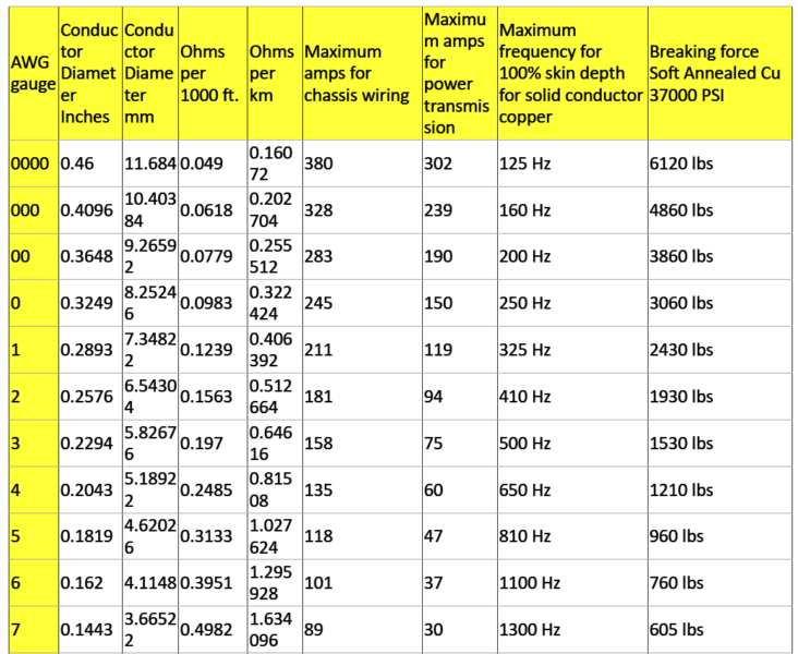
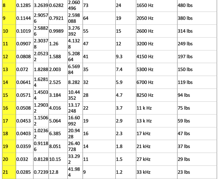
Now let us talk about this AWG or American Wire Gauge system, which we use for finding the diameter of a wire. In this system, we calculate the diameter by using one standard formula that looks like this: D(AWG) = 0.005 × 92((36 – AWG)/39) inch.
Now when we have those special wire sizes like 00, 000, 0000 and so on then we treat them as -1, -2, -3 and so on, because that makes more mathematical sense instead of saying double nought or triple nought type.
How The Gauge Steps Work
So in this American Wire Gauge system, every 6 gauge reduction doubles the wire diameter and every 3 gauge reduction doubles the cross-sectional area. So it works somewhat like decibels in signal or power ranges where we see a kind of logarithmic change.
A more accurate version of this formula was suggested by Mario Rodriguez as
D = 0.460 × (57/64)(awg + 3) or D = 0.460 × (0.890625)(awg + 3).
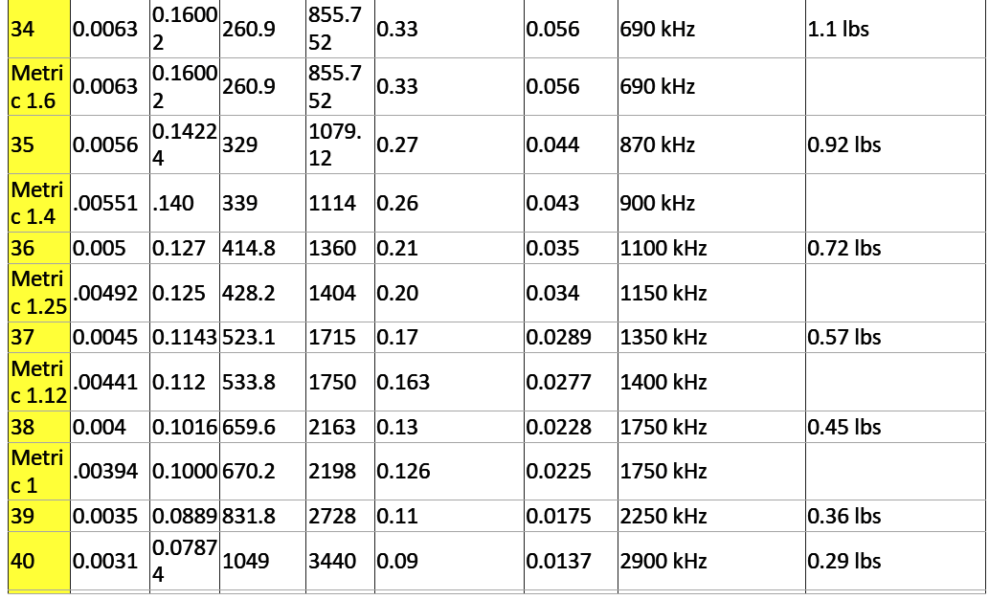
Metric Wire Gauge Explanation
Now when we come to metric wire gauges, there system works differently. In metric gauge scale we take the value as 10 times the diameter in millimeters. So for example a 50 gauge metric wire means it has a diameter of 5 mm.
We must remember that in AWG the diameter increases when the gauge number decreases but in metric gauge it is the opposite. Maybe because of this confusion, most people prefer to show wire sizes directly in millimeters instead of metric gauge numbers.
Current Holding Capability (Ampacity)
Now we come to the current holding part which we call ampacity. Ampacity simply means that how much current in amps a wire can safely carry.
The reference list generally shows ampacity data taken from the Handbook of Electronic Tables and Formulas for American Wire Gauge.
But those are just general guidelines. In actual engineering we must check the voltage drop, insulation temperature limit, wire thickness, thermal conductivity and airflow conditions carefully before finalizing anything.
Conservative Power Transmission Rule
For power transmission, engineers often follow the 700 circular mils per amp rule which is a very conservative safe value. For chassis wiring which is open to air and not bundled, we can go a little higher as those are typical safe levels, but if the wire is very short like used inside battery packs, then we can focus more on the physical size, flexibility and weight instead of only the resistance and current.
Following Electrical Codes
Now for installations that must comply with the National Electrical Code, it is important to follow their specific recommendations. The best and safest way is to talk to your local electrician who will know exactly what is allowed legally and practically.
Skin Effect And High Frequency AC
Now when we deal with high frequency AC circuits, we must know about the skin effect.
This happens because at high frequency the current tends to move along the outer surface of the wire rather than the whole cross-section which increases the effective resistance of the wire.
The frequency values mentioned in the table show the point where the skin depth becomes equal to the wire’s radius, and above this point, we should always consider the skin effect while calculating the resistance or efficiency of the wire.
Busting Force For Copper Wire
Finally the busting or breaking force of copper wire is also given for reference, which is calculated for a smooth, nick-free, soft annealed copper wire having a tensile strength of around 37,000 pounds per square inch.
This gives us a rough idea about the wire’s mechanical strength and how much tension it can handle before breaking.

Need Help? Please Leave a Comment! We value your input—Kindly keep it relevant to the above topic!