In this post I have explained an induction cooker/heater design which may be powered from a solar panel voltage. The idea was requested by Mr. Vamshee
Technical Specifications
My name is Vamshee and i am from hyderabad , India I am a small time entrepreneur looking to promote and sell new age products into the market .
Right now really interested in renewable energy resources .
After reading your blog and being following it from a while I would really appreciate your interest being hired by me if you are interested in the project about induction cooking with solar panel at a very very cheaper cost .( would like to introduce it to the poor ) with the help of govt schemes here in my state .
Specs what i was looking was about
180w solar panel
transformerless inverter ( built inside the induction cooker)
max output of 500W induction stove ( Coil type )
Usage for : heating water,milk , make one time meal in a day .
I am sorry if the specs i gave you might be wrong as i am not from a science background ,but just some calculations reading from the internet . so i have no idea about this , but just have the concept and can sell the product .
I have gone through 12v cooking pans and stuff like those on google but in vain to find any solutions .
I hope to hear from you soon about this project and make it prospective to talk about a bright future .
Regards
Vamshee
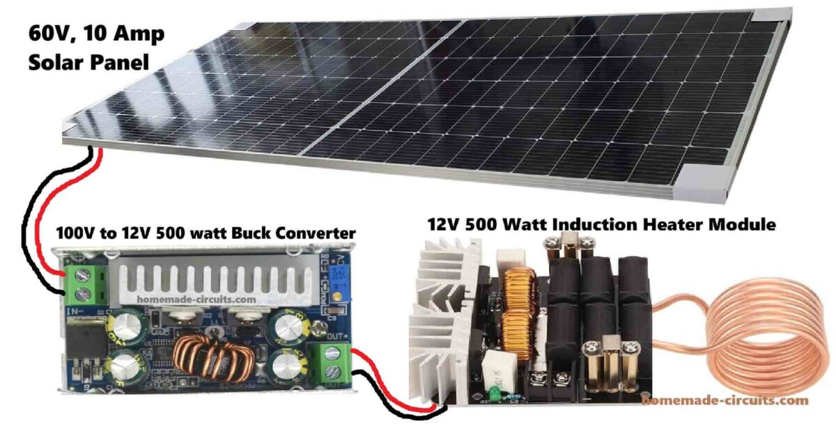
Simple Method: Just Hook up any Standard Induction Heater with a Calculated Solar Panel! That's all!
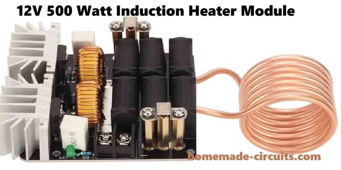
Step #1: I would recommend purchasing a standard 500 watt Induction heater, rather than building yourself at home.
The specification of the induction heater can be 12V 500 watt. This would mean the induction heater would require a maximum current of 500/12 = 41.66 amps or 42 amp current.
Step #2: Buy a solar panel rated at 500 watt. I would recommend getting a 60 V panel. So, 500/60 = 8.33 amps. That means the solar panel needs to be 60V, 10 amp rated.
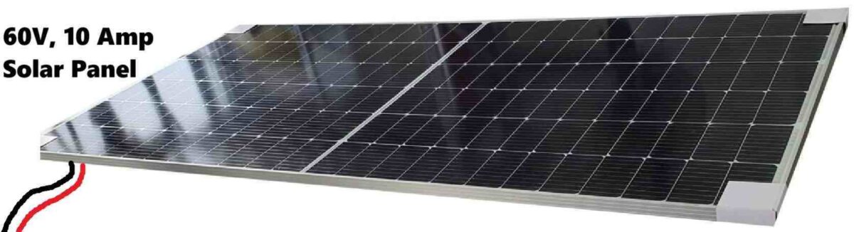
Now, this solar panel output needs to be stepped down to 12V for the induction heater., so we need a buck converter for this.
Step #3: Buy or build a Buck Converter rated to handle 100V input and produce adjustable output.
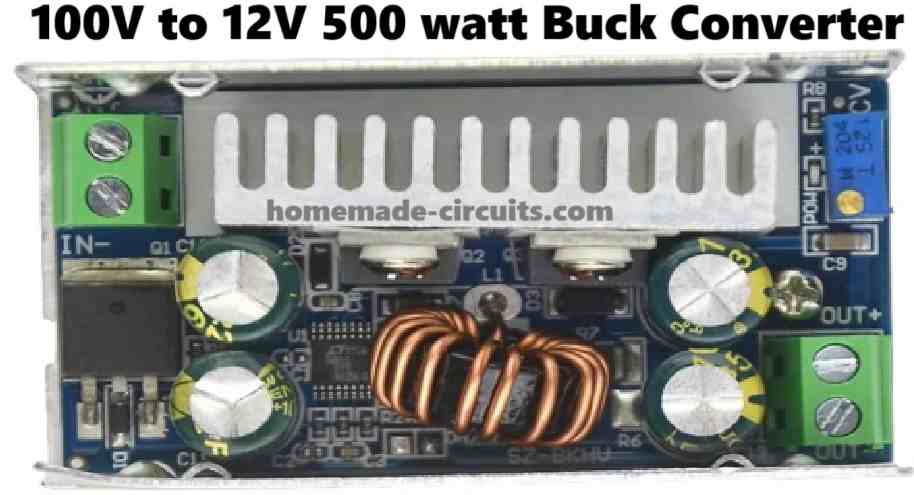
If you want to build your own buck converter circuit, then can very easily build and customize it, as per the instructions provided in this article.
Step #4: Hook Up the buck converter with your solar panel output and adjust the buck converter output to match the operating voltage of your induction heater.
Step #5: Connect the induction heater with the set output from the solar panel integarted buck converter, and that's it! You have now completed your solar induction heater circuit and are ready to cook anything you want with this set up.
Using IC IR2155 Oscillator
As per the specifications a 500 watt output is intended to be achieved from a 180 watt solar panel which may not be feasible in the practical world, therefore the correct solar panel parameter for the proposed solar induction heating system should be approximately 600 watt, or two 180 watt panel in parallel can also be tried for optimal results, this won't be cheap, though.
The panel specs could be anywhere from 30 to 44 V and the amp rating between 20 and 10 amps, and will require a buck regulator in order to step down the voltage to the required levels for the induction heater circuit.
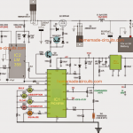
A suitable induction heater circuit can seen below which uses a half bridge driver topology, the schematic is pretty straightforward and may be understood as follows:
Circuit Diagram
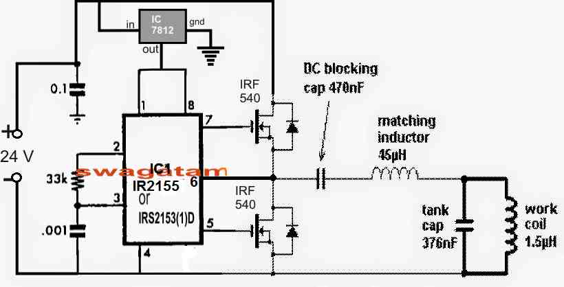
The circuit is driven from a 24 V DC supply, at current ranging up to 15 amps. A 7812 voltage regulator drops the input voltage to 12V for the driver IC which is a standard half bridge driver IC IRS2153 or any other similar.
The push pull output from the IC drives a pair of mosfets which in turn forwards the oscillations to the main work coil of the induction heater via a DC blocking capacitor and an impedance matching inductor.
The blocking capacitor prevents excessive current from passing through the work coil and stops damaging the mosfets while the inductor makes sure no disturbing harmonics get into the line and induce inefficiencies into the system.
The 376 nF tank capacitors are used to achieve a resonance with the work coil at about 210 kHz frequency which is set by the R/C network across pin2 and pin3 of the driver IC. The 33k resistor could be made variable for fine tuning or optimizing the resonance effect.
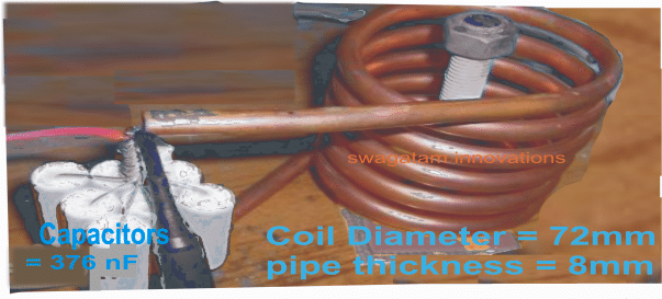
The Work Coil Size
The work coil dimensions and the resonant capacitor arrangement are provided in the image below:
Buck Converter Specifications
A buck converter for converting the panel high voltage to the required 24 V for the induction heater may be built with the help of the following diagram:
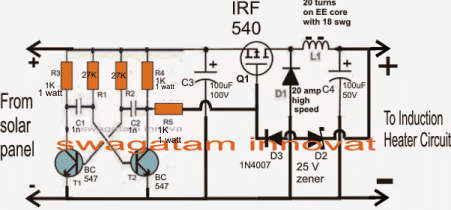
T1, T2 together with C1, C2 and the associated resistors form a classic astable multivibrator (AMV) with a set frequency of around 30 kHz.
The panel volatge is fed to the above AMV and oscillated at the said frequency before feeding it to the buck converter stage made by employing a mosfet and an associated diode, inductor stage.
During the switch OFF periods an equivalent amount voltage is delivered from L1 in the from of back EMFs which is appropriately filtered and supplied to the connected induction heater circuit across the output terminals.
C4 makes sure the converted bucked voltage is free from any ripples and helps in producing a cleaner DC for the induction heater circuit.
The regulated 24 V DC at the outputs may be achieved by roughly winding the correct number of turns for L1 through some trial and error and also by the incorporation of D2 which ultimately stabilizes the output voltage to the required levels.
Questions & Answers
Thanking you Sir for this Circuit Idea, actually I am working as a Service Engineer for Solar Inverter, Solar Panel, EV Charger, Lithium Battery, UPS, Voltage Stabilizer, etc. for UTL SOLAR (Fujiyama Power Systems Limited, N. Delhi) at West Bengal. Now I am working for a better Solar Cooking Circuit and Device for my own use. I have been using the Solar Cooking device successfully (assembled by me before one year) from about one year for my own use. Now I want to improve the circuit and the device.
Thanking you,
Sekhar Chowdhury.
sechowdhury63@gmail.com.
You are most welcome Shekhar,
Glad to know about your deep knowledge in the field of solar cookers.
Please feel free to ask or discuss, if you have any doubts or confusions…i will be happy to help…
Anek dhanyabad, Thanking You Sir for your reply.
No problem Sekhar, it is my pleasure…
Can my two 12V, 150Watts pannels (either connected in parallel as 12V, 300Watts or in series as 24V, 300Watts) work well too with this circuit?
For the given circuit, a 24V would work better. So connecting the two panels in parallel to generate 24V 150 watt appears to be a better choice.
Is the work coil the 500w heater?
Yes, it is!
What is EE core?
These are E cores:
ayya, i am from a spritual organitation, we have lot of non working induction stove. is it possible give power directly to the induction coil and use. just simple on and off is enough, AC or DC what power and what voltage we should give
Hello bhaktimaya,
I don’t think that may be possible. It is not possible to supply power directly to the coils and make them work. You will need a specialized, well calculated, matching oscillator circuit for powering the induction coils.
can you give detail of the circuit just for on and off, no other options required, and what is needed and what will be the cost
I could not understand what you meant by ON OFF circuit, due to mean oscillator circuit?
yes oscillator circuit, which your replied. can you pls give the details with diagram
Induction heater circuit is given in the following article:
https://www.homemade-circuits.com/simple-induction-heater-circuit-hot/
Mr.vamshee please share your contact details
I am harish
9440668851
Please call me if possible
sir i tried solar powered induction heater, it is not working, whats wrong i cannot trace, i think 6th pin of ic should be connected at the junction of drain source of mosfet where the DC blocking cap is placed.
Sanjay, you are right pin#6 must go the junction of the drain source of the mosfets and the blocking capacitor. I will correct the diagram soon.
I think the diagram should be designed in the following manner, as suggested in the datasheet of the IC:
hello
can i use 100uH coil in place of 1.5uH. what changes required?
how to use cooker coil in DC?
100uH cannot be used in place of 1.5uH
Please, I was looking for a manufacturer of this design for a project in Nigeria when i stumbled upon this
Please can you send me a message via my email lekan.latubosun@gmail.com
Sorry, I do not have any information about the manufacturer. The idea is actually simple, purchase a ready made induction heater circuit and connect it with an appropriately rated solar panel.
Hello Sir, How to make a 1000watt DC induction cooker which can be operated by Solar Panel. Can you provide us circuits? please guide us…
Hello Varun, you can use the 1st concept presented in the link below
https://www.homemade-circuits.com/simple-induction-heater-circuit-hot/
use a 30 V 40 amp solar panel, and make sure to use good heatsinks for the MOSFeTs
Dear, I am from Ecuador, my name is Carlos Duque, I am looking for 60Volts 100 amp, induction circuit for induction cooking, I produce DC infrared cooker, but induction is more efficient, please if you can contact me for starting this business, please let me know
regards
I am really sorry Carlos, I only have a theoretical knowledge regarding induction heating, practical knowledge is not good. So it will difficult for me to guide you in this regard with confidence.
Can DC induction coil available in Market for DC induction stove..?
You can probably find it in amazon….
How..? Please help me
search for “induction heater Coil” in amazon
what inverter topology have you used in this circuit ?
first one is half-bridge, second one is buck converter
half bridge with quasi or series converter topology ?
it is a series resonant topology
Y’ello Swagatam,
Am just a beginner and not well vast in electronic and induction,but i want to make a cooker which…………
> uses a 6v or 12v batteries
> can cook for a day
Am sorry if my description is not good,so can you help me with its schemetic and how should i work on it
thanks
Hi mwa, you can try the concept which is explained in the above article. But you can achieve your plans only after gaining good practical experience with these circuits. First try to build a small sample circuit, if you succeed then you can proceed slowly with bigger ones.
Hello Sir, I hope you put the whole fitter and planning for such work but runs on 12-volt battery and AMP to not more than 5 per hour and we are waiting for your response sir
hello Mmdoh, I have explained it here
https://www.homemade-circuits.com/2016/09/designing-induction-heater-circuit.html
Hello sir!! We (me and my team) are looking forward to develop a solar induction stove to be used in households on regular basis. So can you please tell us that what specifications are required for the same so that cost also remains minimized?
Contact No.-9971650252
Hello Aayushi,
Induction heater is a difficult project which will need to be practically built and experimented for finalizing an optimized design, I would recommend you to build the following simplest induction heater circuit:
https://www.homemade-circuits.com/2013/10/simple-induction-heater-circuit-hot.html
and then gradually modify its coil so that it can take the shape of a cook top induction heater.
A detailed video is presented on youtube using the above circuit, you can watch that for a detailed guidance.
Hi,
I am looking 9v battery or AA battery water heater for boil of 100ml water. Please suggest me how to do this?
Hi, you can try the following concept:
https://www.homemade-circuits.com/2016/05/small-induction-heater-circuit-for.html
but 9V PP3 batt will not work…you may have use many number AAA cells for getting the results.
Hi Swagatam,
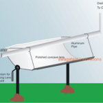
I will try this circuit. All i need to know is a bit detail about how to make the work coil. Is it made with a hollow copper pipe?
Hi, yes it needs to be made using hollow copper tube for facilitating water cooling through the pipe if required
Hi I have just joined. This is a brilliant website and i have been looking for a while but stumbled across this 1. My name is Keith and I wondering if i could use the induction heater at the starting point of copper pipe to heat the whole pipe so water flows through from a further distance to have more heating time?
Hi, thank you for liking the website, I appreciate it. You can definitely build the intended project for heating water through pipe, however I would recommend the following circuit instead, since it is a tested design:
https://www.homemade-circuits.com/simple-induction-heater-circuit-hot/
hi sir,
i would like to implement a smaller version of this one as my mini project…like for a 8W/12V DC solar panel…what changes will i have to make in the circuit…
Hi angela, 8 watt is very less, I don't think you can make anything red hot with this power.
still you can try, by using thinner wires for the work coil, and reduce its diameter slightly, also you can tweak the 33k resistor a bit and find the optimal frequency to increase the efficiency