In this post I have explained how to build a energy efficient soldering iron station circuit for achieving maximum power saving from the unit, by ensuring that it is automatically switched OFF when not being used for sometime.
Written and Submitted By: Abu-Hafss
DESIGN#1: OBJECTIVE
To design a circuit for solder iron which would not only save the energy but also avoid the over-heating of solder iron tip.
ANALYSIS & PROCEDURE:
a) Switch ON and warm-up the solder iron for about 1 minute.
b) Check if the solder iron is present in stand or not.
c) If not present, the solder iron gets 100% power, directly from AC mains.
d) If present, the solder iron gets 20% power thru regulated circuit.
e) Go to procedure (b).
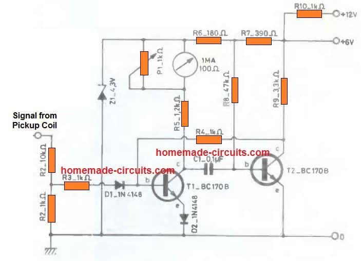
Circuit Set up and Schematic
CIRCUIT DESCRIPTION:
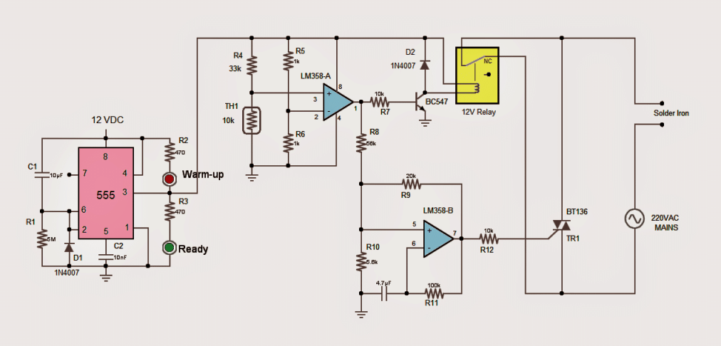
a) A 555 timer is configured to delay power on for about minute. During this period the solder iron is connected to AC mains thru the "NC" contacts of the relay.
The red LED would indicate the initial warm-up of 1 minute after which it goes off and the green LED would light up to indicate that the solder iron is ready to use.
b) IC LM358-A is configured as voltage comparator to check the presence of the solder iron in its stand using a thermistor.
The (-)ve input of the comparator is provided with a reference voltage of 6V using R5/R6 potential divider. The (+)ve input is also connected to a potential divider formed with R6 and the thermistor TH1.
If the solder iron is not present in its stand the thermistor would acquire the room temperature. At ambient temperature the resistance of the thermistor would be roughly 10k thus the potential divider R4/TH1 would provide 2.8V at the (+)ve input, which is less than 6V at the (-)ve input.
Thus the output of LM358-A remains low and there is no change in the operation; the solder iron continues to get power thru the "NC" contacts of the relay.
c) If the solder iron is present in its stand, the increase in temperature will increase the resistance of the thermistor. As soon as it crosses 33k, the potential divider R4/TH1 provides more than 6V at the (+)ve input hence, the output of LM358-A goes HIGH.
This energizes the coil of the relay via NPN transistor T1 and therefore the solder iron is disconnected from the AC mains.
The HIGH output of LM358-A also powers ON the LM358-B network, which is configured as an astable oscillator with a duty cycle of about 20%.
The duty cycle is controlled thru the potential divider R8/R10. The output is connected to the gate of triac BT136, which conducts and switches on the solder iron for 20% of a cycle, thus 80% of power is saved while the solder iron is at rest.
NOTE:
1) Since the triac (operating AC mains) is directly connected to the rest of the circuit via R12, care should be taken and the circuit should not be touched when powered on. For protection, opto-isolator like MOC3020 can be incorporated.
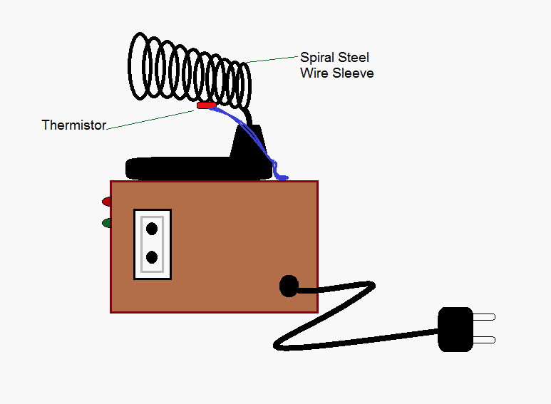
2) Any value of thermistor may be used but, the value of the R4 should be selected accordingly such that R4/TH1 should provide about 3V at normal temperature. Moreover, the increase in temperature of the spiral steel wire sleeve due to the presence of solder iron should also be taken into account.
3) The triac cannot be replaced with a relay because of two main disadvantages:
a. Continuous rattling sound of the relay contacts could be annoying.
b. The continuous and swift switching of the relay contacts will cause high voltage sparks.
4) The thermistor legs should be covered with heat resistant insulation sleeves and then installed suitably on the iron stand.
5) The 12V DC supply (not shown) may be obtained from AC mains using a step-down 12V transformer, 4 x 1N4007 diodes and a filter capacitor. For details, read this article https://www.homemade-circuits.com/2012/03/how-to-design-power-supply-simplest-to.html
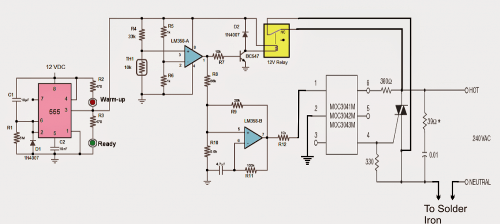
The above explained circuit of an energy saver soldering iron is appropriately modified and corrected in the following diagram. Please refer to the comments for a detailed info regarding this modification:
The next concept below discusses another simple automatic soldering iron power shut off timer circuit which ensures that the iron is always switched OFF even if the user forgets to do the same during the course of this routine electronic assembly job work. The idea was requested by Mr. Amir
Design#2: Technical Specifications
My name is amir of Argentina ... and I am repairing technician but I have a problem I always forget the soldering iron on, ested can help me with a circuit for self disconnection time, my idea is ...
after a while the low power soldering iron in half ...
and sounds a beep beep until you press a button and set the counter to zero, but if not pressed after once off.
from already thank you very much.
Circuit Description
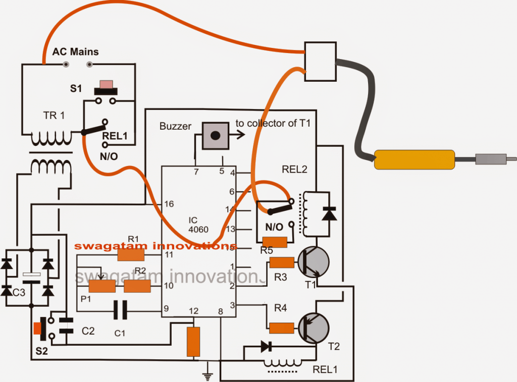
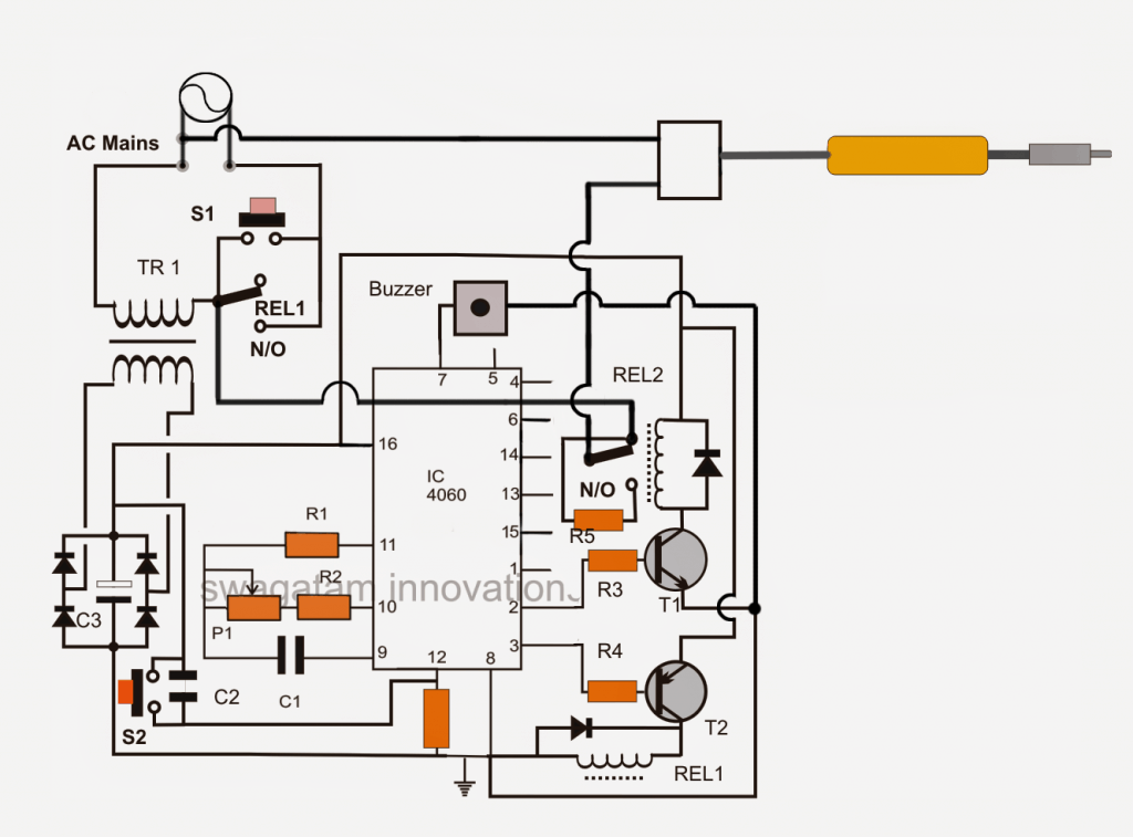
Initially when the circuit is powered via mains AC, it stays switched OFF due to REL1 contacts being in a deactivated state.As soon as S1 is pressed the IC 4060 momentarily gets powered via TR1, bridge network activating T2.
T2 instantly energizes REL1 coil at its collector which in turn activates the N/O contacts of REL1 wired across S1.
The above activation bypasses S1 and latches the circuit so that now releasing S1 keeps REL1 activated.
This also switches ON the connected soldering iron via REL1 and N/C of REL2.
Now IC 4060 which is wired as a timer being powered begins counting the timing period set by adjusting P1 as per the requirements.
Suppose P1 is set for 10 minutes, pin3 of the IC is set for becoming high after 10 minutes interval.
However this also means pin2 of the IC would go high after 5 minutes interval.
With pin2 switching ON first after 5 minutes triggers REL2 which now shifts its contacts from N/C to N/O. Here N/O can be seen connected to iron via a high watt resistor, meaning now the iron gets switched to receive less current making its heat lower than the optimal range.
In the above condition T1 being switched ON, the buzzer at pin7 gets the required ground supply via T1 and starts beeping at some frequency indicating the iron being shifted to low heat position.
Now if the user prefers to restore the iron to its original condition could press S2 resetting IC timing back to zero.
Conversely if the user is inattentive, the condition persists for another 5 minutes (total 10 minutes) until pin3 of the IC also goes high switching OFF T1,/REL1 such the whole circuit now shuts down.
Circuit Diagram
Parts List for the proposed automatic soldering iron power saver circuit
R1 = 100K
R2, R3, R4 = 10K
P1 = 1M
C1 = 1uF NON POLAR
C2 = 0.1uF
C3 = 1000uF/25V
R5 = 20 OHMS 10 WATT
ALL DIODES = 1N4007
IC PIN12 RESISTOR = 1M
T1 = BC547
T2 = BC557
REL1, REL2 = RELAY 12V/400 OHMS
TR1 = 12V/500MA TRANSFORMER
S1/S2 = PUSH TO ON SWITCHES
BUZZER = ANY 12V PIEZO BUZZER UNIT
A redrawn version of the above diagram can be seen below, it was suitably improved by Mr. Mike for helping easier understanding of the wiring details.
Very Cheap yet Effective Soldering Iron Energy Saver Protection Circuit
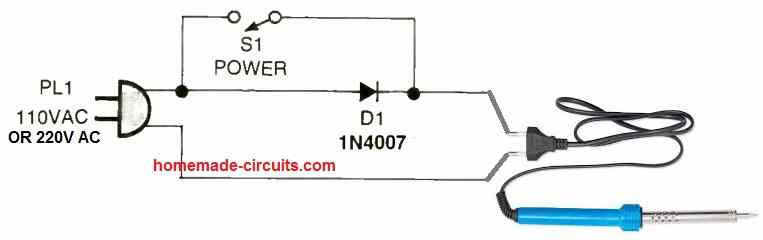
This is perhaps the cheapest soldering iron protector and energy saver circuit. As we know that when AC mains voltage is passed through a single rectifier diode, the diode allows the half cycles of the AC mains to pass through it, and blocks the other half cycle of the AC mains.
This means, only 50% power is allowed to pass through the diode. In this circuit we take the advantage of this half wave rectification principle of the diode and exploit it to control the power through the soldering iron.
As can be seen in the above diagram, when the iron is not being used and in idele state, the switch S1 is opened to enable only 50% power to the iron through the diode.
This allows the iron to be in a reasonably good temperature yet causes only 50% power to be used.
While using the iron the switch S1 is closed so that the diode is bypassed and the full AC supply is able to reach the soldering iron restoring its full temperature quickly.


Questions & Answers
I need a circuit for digital circuit diagram controlled for steam flat iron.
Good Job guys!!! Well done this circuit works pretty well. May God give you extra knowledge.
Glad it worked for you…keep up the good work.
Hi
Thanks for pointing out the error. Swagatam, would you please change the labels in both the diagrams:
R4 ====> R6
R6 ====> R4
For thermistor, yes I did not mentioned NTC or PTC but the statement "the increase in temperature will increase the resistance of the thermistor" in para (C) clearly depicts that it is PTC.
All is well !!!
Thanks Abu-Haffs, I think it's all done now, please confirm…..
Thanks Swagatam.
But there are two more to be changed to "R4/TH1"
One in para (c) and the other in NOTE (2).
…done!
Hi Abu-Hafss,
changing the text instead of the image will be easier…I'll do it shortly…
Hey,awesome circuit,may I ask what is the voltage of the 0.01uf cap in series with the 39 ohms resistor at the AC side?How about the 39 ohms resistor,whats the wattage?Thank you
thanks edwin, the capacitor is a regular 50V cap, and the resistor can be an ordinary 1/4 watt resistor
Thank you very much for your immediate response.
There is a problem with this circuit. The trigger voltage given to the triac is not referenced to either terminal 1 or terminal 2 of the triac, in other words the gate is isolated. This way there will be no current flowing in or out of the gate and the device will never get triggered. Correct me if I am wrong in my observation.
Kind regards
Thank you Swagatam
OK, thanks Abu-Hfass,
I have updated the new diagram using the MOC opto-coupler, please check it out.
The following para would definitely give the core idea of saving energy:
"The HIGH output of LM358-A also powers ON the LM358-B network, which is configured as an astable oscillator with a duty cycle of about 20%. The duty cycle is controlled thru the potential divider R8/R10. The output is connected to the gate of triac BT136, which conducts and switches on the solder iron for 20% of a cycle, thus 80% of power is saved while the solder iron is at rest."
Hmm, yes it reveals that you have not studied the circuit and my description. I have clearly discussed in note no. 3(a) and 3(b) that the relay cannot be used.
I have assembled it already without the opto coupler. Please spare a few moments to sort out the issue because frankly I have no practical experience of triacs.
Hi Abu-Hafss,
My idea was to replace the triac MT1, MT2 leads with relay contacts (NO) of a second relay which would be triggered by R12 opamp via a transistor stage
actually i have not studied the circuit yet, I am just trying to solve it by looking at the diagram….and I believe that the triac is supposed to be triggered by the lower opamp and override the first relay contacts…so according to me this could be done by using another relay.
Hi Swagatam
According to your idea, the neutral of the mains should be grounded. And that has to be done manually using a multi-tester, which is not a good idea. I am sure MOC would do the job, and I might need your help to get it done 🙂
Thanks Abu-Hafss,
However I don't think your new idea would solve the issue either, because in your diagram there's no way the triac would be able to get a positive trigger from the MOC IC.
A better idea would be to use another relay driver stage with the R12 end.
Chinmoy
You are correct! Thanks for pointing it out.
An opto coupler would be definitely solve the issue.
I would ask Swagatam to update the revised schematic as below
Kind regards to you as well 🙂
I like to build this project mr. Swagatam. Hopefuly this will help me save energy consumption..
sure Mr.Norie, I appreciate your interest.