A dip meter or a grid dip meter can be considered as a kind of frequency meter whose function is to determine the resonant frequency of an LC circuit.
For this, the circuits don't have to 'radiate' any waves or frequency across each other. Instead, the procedure is implemented simply by placing the coil of the dip meter close to the external tuned LC stage in question, which causes a deflection in the dip meter, allowing the user to know and optimize the resonance of the external LC network.

Application Areas
A dip meter is normally applied in fields that require precise resonance optimization, such as in radio and transmitters, induction heaters, Ham radio circuits, or in any application intended to work with a tuned inductance and capacitance network or an LC tank circuit.
How the Circuit Works
To find out exactly how this operates we could go right to the circuit diagram. The components that constitute a dip meter are usually quite similar, they work with an adjustable oscillator stage, a rectifier and a moving coil meter.
The oscillator in the present concept is centered around T1 and T2, and is tuned through capacitor C1 and coil Lx.
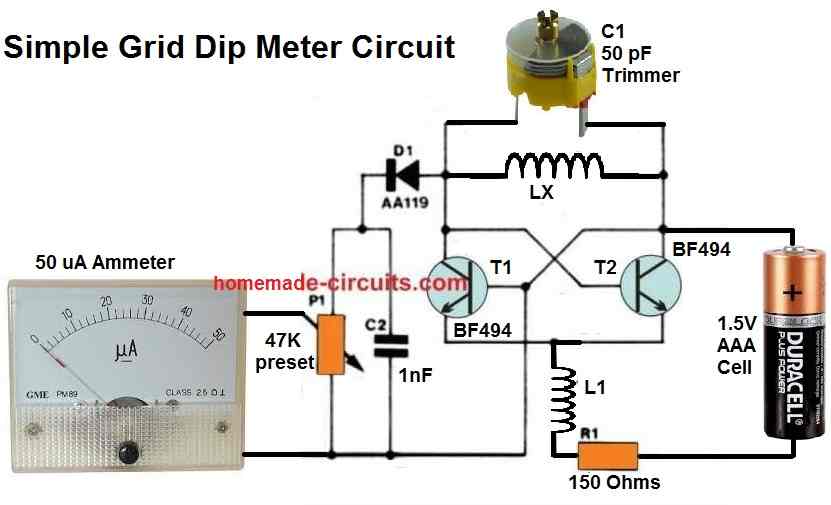
The coil LX is fixed outside the metallic enclosure where the circuit needs to be installed, so that whenever felt necessary the coil could be quickly replaced with other coils to allow the meter range to be customized.
Once the dipper is powered ON, the generated oscillating voltage is rectified by D1 and C2 and is then transferred to the meter through preset P1, which is used for tuning the meter display.
Main Working Feature
Nothing looks to be unconventional thus far, however now I have explained about the intriguing feature of this dip meter design.
When inductor Lx is inductively coupled with the tank circuit of another LC circuit, this external coil quickly begins pulling power from the our circuits's oscillator coil.
Due to this the voltage supplied to the meter falls causing the reading on the meter to "dip".
What goes on practically can be understood from the following testing procedure:
When the user brings the coil Lx of the above circuit near any passive LC circuit having an inductor and a capacitor in parallel, this external LC circuit starts sucking energy from Lx, causing the meter needle to dip towards zero.
This basically happens because the frequency generated by our dip meter's Lx coil does not match with the resonance frequency of the external LC tank circuit. Now, when C1 is adjusted such that the dip meter's frequency matches the LC circuit's resonance frequency, the dip on the meter disappears, and the C1 reading informs the reader about the resonance frequency of the external LC circuit.
How to Set Up a Dip Meter Circuit
Our dipper circuit is powered and set up by adjusting the preset P1 and the coil Lx to ensure that the meter delivers optimum reading display, or just about the highest possible needle deflection.
The inductor or coil in the LC circuit that needs to be tested is positioned in close proximity to Lx and C1 is tweaked to make sure that the meter produces a convincing "DIP". The frequency at this point could be visualized from the calibrated scale over the variable capacitor C1.
How to Calibrate the Dip Oscillator Capacitor
The oscillator coil Lx is built by winding 2 turns of 1 mm super enameled copper wire over an air core former having a diameter of 15 mm.
This would provide a measurement range of around 50 to 150 MHz resonance frequency. For lower frequency just go on increasing the number of turns of the coil Lx proportionately.
To make the C1 calibration accurately, you will need a good quality frequency meter.
Once the frequency is known which gives a full scale deflection on the meter, the C1 dial could be calibrated linearly across the whole for that frequency value
A couple of factors that must be remembered regarding this grid dip meter circuit are:
Which Transistor can be used for Higher Frequencies
The BF494 transistors in the diagram can deal with up to 150 MHz only.
In case larger frequencies are required to be measured then the indicated transistors should be substituted with some other suitable variant, for example BFR 91, which could enable approximately 250 MHz range.
Relationship between Capacitor and Frequency
You will find a variety of different options which could be applied instead of the variable capacitor C1.
This might as an example, be the 50 pF capacitor, or a less expensive option would be to utilize a couple of 100 pF mica disc capacitors attached in series.
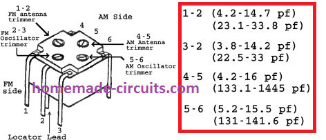
A different alternative could be to salvage a 4 pin FM gang condenser from any old FM radio and integrate the four portions, each section being approximately 10 to 14 pF, when attached in parallel using the following data.
Converting Dip Meter to Field Strength Meter
Lastly, any dip meter, including the one which is discussed above, could, practically also be implemented like an absorption meter or field strength meter.
To make it work like a field strength meter, eliminate the voltage supply input to the meter and ignore the dip action, just concentrate on the response which produces the highest deflection on the meter towards the full scale range., when the coil is taken near to another LC resonance circuit.
Field Strength Meter
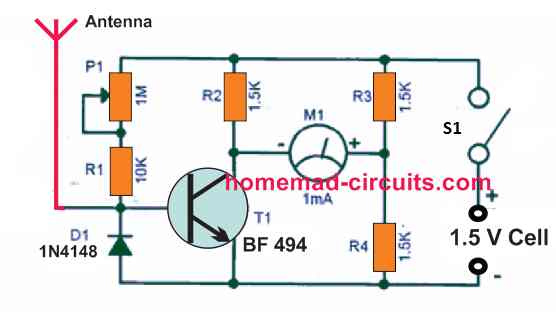
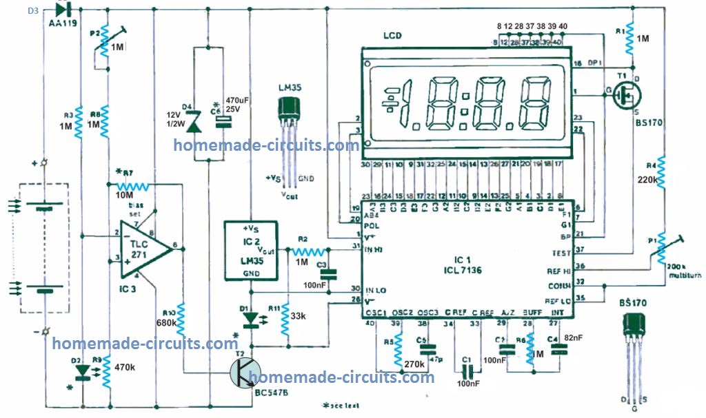
This tiny yet convenient field strength meter circuit enables users of any RF remote controller to validate if their remote-control transmitter is working efficiently. It evens shows if the trouble is with the receiver or the transmitter unit.
The transistor is the sole active electronic component in the simple circuit. It is used as a regulated resistance in one of the arms of the metering bridge.
The wire or rod aerial is attached to the base of the transistor. The rapidly rising high-frequency voltage at the base of the aerial powers the transistor to force the bridge out of equilibrium.
Then, current passes through R2, the ammeter and the collector-emitter junction of the transistor. As a precautionary step, the meter must be zeroed with P1 before switching on the transmitter.
High Frequency Field Strength Meter
For numerous reasons this the following field strength meter can be extremely sensitive. To begin with, there can be range of several wave lengths as is possible between this device and the transmitter. A extremely weak signal will undoubtedly be sufficient while employing this sensitive field strength meter. Finally, the majority of transmitters just have a weak output Strength (for example, 500 mW).
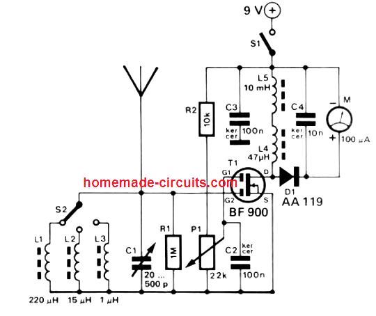
These are typically three of the major factors why this specific field strength meter comes with an RF amplifier stage comprising a Dual gate MOSFET, T1. The amplification element is defined with P1. Switch S2 allows one of the 3 ranges to be determined: 480 kHz to 2.4 MHz (L1); 2.4 to12 MHz (L2) and 12 to 40 MHz (L3). A pole of around 30 cm is going to be adequate to act as antenna. Just like any other RF circuits, proper care throughout the construction process is advised.


Questions & Answers
A question about what type of choke is best suited for L4 and L5 as I asked about the field strength meter earlier, Goran
Any ferrite core based inductor can be used, with the specified mH and uH values.
Hello! This sensitive field strength meter with transistor BF900. The replaceable coils do you have any data on the speed type of core wire thickness. Regards Goran
Wire thickness is not critical, it can be a just 0.3mm thick wire..
I have an induction heater that operatures at frequencies between 40 and 100 kHz. How may turns above 10 do I need to reduce the minimum freq range dow from 50 MHz?
Could I replace the ammeter with a neon bulb and if so what specs?
That will need to be experimented, it is difficult to find out through calculations.
Ammeter cannot be replaced with an LED, because the current is in microampere.
Swagatam please discuss and furnish a tuning indicator circuit with LED and analog meter for solid state radio receiver.
Hi Shankar, Here’s a nice tuning indicator circuit you can try:
https://www.elektormagazine.com/magazine/elektor-197707/57947#&gid=1&pid=1
Hi I was looking for a field strength meter for 300 -500Mhz or circuit dia not to complex can you advise thanks ZL1BCR
500 MHz looks too high, presently I do not have a circuit for measuring this frequency.
Thank you for the email reply, unfortunately I no longer have the facilities to produce PCBs. George, G4EUFL.
Hello, thank you for the circuit diagram of the field strength meter, could you please tell me if a PCB is available. Many thanks George. G4EUF.
I am sorry, PCB design is not available for this project.
Obrigado pela matéria e os dados
My pleasure!
Hello, my email is stanleysmd@gmail.com. I am replying /
commenting re the communication of Stanislaw Chmielarz.
I am a physician (MD) and engineer. I scanned the article
listed by Dr Chmielarz : very interesting … what strikes me is that he (they) are using the RF absorption at a given frequency without a method of comparing returned RF levels against a standard. Perhaps it would be useful to
use absorption parameters at two frequencies, one of which is not strongly absorbed. The returned values of
signal strength viewed as a ratio of absorptions yield a
greater amount of information. Another (somewhat wild ?)
thought occurs… if the neoplasm selectively absorbs at
a specific wavelength, discrete from other tissues, then
higher energy levels might be a means of ablation of the
targeted neoplasm.
I hope these comments reach Stanislaw Chmielarz.
I wish him the best in his endeavors!
stanleysmd@gmail.com
Muito bom vou montar e fazer uso.
I have a PCB for the GDO project and made first tests. Transistors BF199, diode AAP155 frequency unknown 🙂 powered by a battery 1,5V, current achieved 10uA. So I ordered a new diode Schottky SD 101 (30V 0,2A switching time 1ns) and current grow to 640uA and is visible on a VU meter.
Now I am thinking about a conception of a simply calibration method for it.
Thanks for the feedback, so it seems the circuit is working for you, which is great!
I am sending You a link to a device TrimProb which is used for searching cancer tumors:
rebus.us.edu.pl/handle/20.500.12128/10113
I ordered a PCB for this circuit and if I mount this GDO I will let You know.
sure, no problem!
I want to make a GDO for a frequency set to 465MHz using Your schematic. It will be used for a cancer tumor findings. I have a proper transistor set 2N5109 and BF199 for this purpose. I am using regulated capacitor 50pF in paralell to a searching coil which must be changed to achieve such a frequenncy. I use a battery power 18650 (3,6V) and must change a L1 coil nad R1 resistor. I use LED instead of a meter to search for a dip (led off).
Can You help me with this project?
You can easily accomplish by suitably modifying the first circuit above through the given instructions. However, using an LED may not be possible, since that would require an additional complex amplifier filter stage.
Thank You for an answer!
Scientists have found that cancerous tumors absorb this frequency as well as 465MHz * 2 and * 3. I wanted to test it with such a simple device. That’s why I have 2 sets of transistors to build the original version powered by a 1.5V battery and a more powerful 18650 powered.
Thanks for the interesting information, appreciate it, yes you can go ahead with the first project and the necessary modifications.
If I want to change a frequency to 465MHz I ought to change transistors and a coil LX and Cx of the resonance circuit?
That’s correct!!
Czy do zmiany generowanej czestotliwosci wystarczy zmienic wartosci Lx i Cx obwodu rezonansowego oraz tranzystory?
Yes, changing the Lx, Cx and the transistors is enough to increase the frequency capacity of the circuit accordingly