Controlling a heavy electrical appliance with push buttons can be extremely convenient since it allows a solid state approach for operating the parameter both ways up and down by mere push of the relevant buttons. Here I have explained a heat controller circuit using a set of push buttons and PWMs.
Using a Digital Push Button Controller Module
In one of my earlier posts I designed an interesting universal push button controller circuit which could be implemented with any related appliance for achieving a two-way push button control for the particular appliance.We implement the same concept for the present application too.
Let's try to understand the above shown push-button heater controller circuit in detail:
How it Works
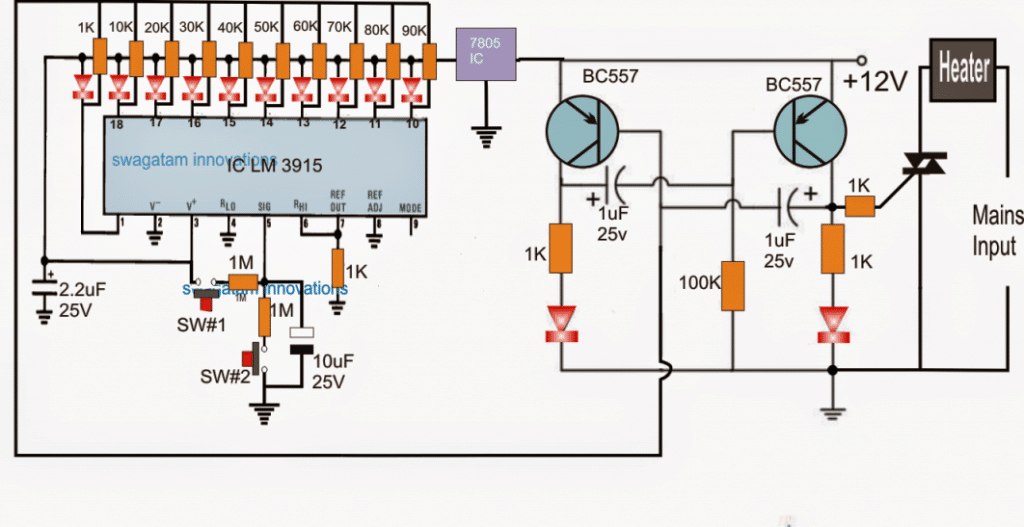
The design can be divided into two main stages, the LM3915 stage which becomes responsible for creating an up/down sequentially varying resistances in response to the two push button's pressing, and the transistorized astable multivibrator stage which is positioned to respond to the varying resistances from the LM3915 outputs and generate a correspondingly varying PWMs. These PWMs are finally utilized for controlling the connected heater appliance.
You may be already knowing that the IC LM3915 is designed for producing a sequentially incrementing output across its pins 1 to 18 to 10, in response to an incrementing voltage level at its pin#5.
We take the advantage of this feature and employ a charging/discharging capacitor at its pin#5 via push buttons for implementing the required forward/reverse sequentially running logic low across the mentioned pinouts.
When SW1 is pushed ON, the 10uF capacitor slowly charges causing a rising potential at pin#5 of the IC which in turn enforces a jumping logic low from pin#1 towards pin#10.
The sequence stops as soon as the push button is released, now to force the sequence backwards SW2 is pressed which now begins discharging the capacitor, causing a reverse jumping of the logic low from pin#10 towards pin#1 of the IC.
The above action is indicated by the chasing red light across the relevant output pins in the same order.
However the actual implementation of the proposed push button controlled heater circuit is carried out by the introduction of the PNP transistor astable PWM generator circuit.
The PWM Generator
This astable circuit generates an approximately 50% duty cycle as long as the resistor capacitor values across the bases of the transistors are at an equilibrium, that is the values are equal and balanced, however if any of these components values are changed, a corresponding amount of change is introduced across the collectors of the devices, and the duty cycle changes at the same proportion.
We exploit this feature of the circuit and integrate one of the bases of the transistor with the sequencing outputs of the LM3915 via an array of calculated resistors which correspondingly change the base resistance of the concerned transistor in response to the pressing of SW1 or SW2.
The above action produces the required varying PWMs or duty cycles across the transistor collectors, which may seen hooked up with a triac and the heater appliance.
The varying PWMs enable the triac and the appliance to conduct or operate under the induced amount ON or OFF switching creating an equivalent amount of increase or decrease in the heat of the appliance.


Questions & Answers
Hi, I wish you had given a graph of the state of the signal at different points in the circuit, it would be useful even if it was only imaginary
Good day Mr Swagatam.
I love this little circuit and I am planning on using it to drive my pencil SMT heat gun. I was wondering if it is atall possible to rather omit the 10 LED’s and use those ten outputs to drive a 2 x 7 segment displays so that 00, if possible, or 01 on the 7 segment displays equals to lowest temperature and 10 on the seven segment displays equals to maximum temperature. I know that the 2 x 7 segment displays needs a driver that uses the 10 outputs from ic LM3915 to display the correct value selected with the pushbuttons SW#1 and SW#2. I just do not have the ability to design and implement such a circuit. I will really appreciate it if you can help me with this extra circuit design and how to incorporate the extra circuit with your existing circuit. I think this extra display circuit will just give my little project that extra finishing touch and looks.????
My pencil heat gun element is rated at 230 volt, 250 watt and 206 ohm. Element size: 6,5 mm diameter x 50 mm, it is a cartridge heater element mounted in a copper heat exchanger that the air flows over. We operate at 220 volt where i live. What value triac can i use in this circuit that will be compatible with the above mentioned ellement? Here is 3 Triac’s that i can find locally: BTA06-600B 35mA = Igt, T1212NH 50 mA = Igt and BT139-600E 35mA = Igt.
All the other circuits that you helped my with, still works beautifully, thank you so much for all your help that you give to us. I really appreciate all your help and patience
Have a lovely day.
THANK YOU Mr Swagatam.
Thank you so much Ian, for your kind feedback.
However, I would advise you not to try the above concept since it is created through my imagination only and I am not sure whether it will work 100% or not.
Instead I can provide you with a similar 4017 based circuit. But in this circuit you can only increment the heat value with a single push button. There’s no second button to reduce the heat step wise.
For the reduction you will have to press the reset button which will bring the heat level to zero so that you can again start incrementing it step wise until the desired level is reached.
Yes BTA06-600 triac will be just fine for your 250 watt load
Good day Mr Swagatam.
Thank you for a very quick reply.
I am a bit confused now, do you mean that the above circuit with ic LM3915 was not tested and might not work 100% or the modified version of this circuit that i have asked for. The reason why i am confused, is, i can not find any other circuit of the LM3915 that has been modified.
Please send me the circuit diagram based on 4017. If there is a modified LM3915 circuit available, please send it to, i will gladly test it for you and be happy to send you feedback about the outcome.
If it is possible, could you please design me a circuit that will work like i asked for in the first reply.
Thank you.
Hi Ian,
Yes the above circuit is not a confirmed design, so better not to try.
Here’s the 4017 design which you can try. It is a PWM triac controller. On each pressing of the push button at pin#14 of 4017, it output increments and introduces a selected resistor value to pin#5 of the IC 555 which causes a resistive divider to form between the 4017 output resistors and the 555 pin#5 resistor.
This in turn causes the output pwm of the 555 to vary, causing the triac to switch ON OFF at a variable rate.
I have used only 3 outputs from the 4017, you can increase the number of outputs by repeating the sequence and by adding more incrementing resistor values to get more variable heat options.
Hello Swag, I have to say I have been coming here to your site for at least a year and a half, regularly to check out your cool circuits, and it is my favorite site on the web! I recently bought a house, and it had a relatively newer dishwasher in it, but I installed mine because it matched my eye for the new scheme in kitchen. So since have re-purposed most of the old one into various projects, and the heating coil is just like new (It states 600 Watts) and I have been wanting to build a PCB hot plate for some time now. I also have some large chunks of 1 1/4″ thick aluminum stock, if I were to drill holes throughout the aluminum plating and re-bent the heating coil routing through the holes, do you think it could get hot enough for PCB work if the right circuit was fixed to the coil? I was looking at the circuit above, but I thought I would ask. I also have type-k thermo-couple I.C., and probe, and LCD display to implement if said project is feasible, if not feasible to get hot enough then would have to look at buying heater cartridges, just thought I would run this by you as your expertise excel in the inverter/power supply field!! Thank you so much for all the help you provide the internet community with your plentiful, and more than gracious circuits. It sets a good example for others in the world to follow, in terms of sharing your knowledge with people you don’t even know!!! Thank you Mr. Swagatam!!! Regards, Michael Sakach….Electronics Hobbyist, and Swagatam Follower.
Thank you Michael, It’s a pleasure to have you in my site, appreciate it lot.
Although I do not have much practical experience with heater coils and gadgets like PCB hot plate, I believe that the project is definitely achievable. However I am not sure regarding the magnitude of heat that may be required for this. But no problem, the heat can be always regulated with the help of a dimmer switch, so you can go for the heavy duty coils and then regulate it through a dimmer switch as per your application limits. Let me know if you have any further queries, will be happy to help!!
What should be the resistance and wattage of the resistor at the base and emitter of the transistor at the circuit in the link above so that i will get 5amp at the output i'm using tip142?
it will work for 5 amps also…
see the parts list below the diagram…
Pls this is the last i'll post here…give me the configuration of the single lm317 with a transistor and what transistor should i use…and also is there any disadvantage of using such method
it have already given the link in the previous comment, here it's once again, the first circuit.
https://www.homemade-circuits.com/2012/05/dc-to-dc-double-cell-phone-charger.html
But sir how i'm i going to connect 5pot to each circuit and connect in parallel…that'll be difficult to adjust the voltage…what if i connect all the inputs pins of the ic in together and also connect all their adjust pin together and then use a diode to connect the output together and then use the different terminals to construct the given circuit?2.what value of diode should i use 3.to remove the current limiter stage i have to remove the transistor at the adjust pin with the limiter resistor right?…i'm just soldering the auto cutoff stage but i've not assembled the charger circuit because of this
victory please post your comments in the relevant article, because this article is not related to your questions.
response to your another question: the relay may be ON due to leakage current from the opamp….use a 3v zener diode in series with the base of the transistor this will solve the issue.
you can use calculated fixed resistors for the pots.
diodes can be 1N5408.
you can use a single 317 also and put a transistor over it for increasing current.
Hello sir, i bought the components today i'm using 6a10diode as rectifier 12v 10amp 400ohm relay and i couldn't find any single 5amp voltage regulator so i've decided to use 5 lm317 in parallel please help me as how i can connect it (2) i need to charge my battery with 1/7.5 of it's ah value thats 38/7.5 which will give me around 5amp but 0.6/5 gives me around 0.12ohms as the resistor value for current limiting and i couldn't see that value so does that mean that i should remove the current limiting stage?if yes tell me the components to remove in the circuit so that if i rectify my 18v 5a transformer i can just adjust the voltage but the current will remain 5amp…i'm sorry i'm bothering u much sir but please help me out as i'll be using this to charge my inverter with automatic changeover
Hello victory, make 5 circuits with the following configuration each:
2.bp.blogspot.com/-q-nD43obNhQ/TuOI-cTbCnI/AAAAAAAAALQ/yq7OTDf5jEs/s1600/IC+317+Power+Supply%252C+Simplest.png
then join their inputs in parallel and connect to the source voltage…and also connect their output together but through individual diodes and then use the voltage from the common point of these diodes to charge the battery.
make sure to use separate large heatsinks for each of the ICs.
or alternatively you can use a single IC and add a transistor for increasing the current as shown in the first diagram here:
https://www.homemade-circuits.com/2012/05/dc-to-dc-double-cell-phone-charger.html
you can forget about the current control stage I think it is not important since the input is just 5 amps.
But if i rectify a 15vac from a transformer of 5amp and feed it to lm196 will the output be equal to 15v 5amp i'm using 1n4007 as the rectifier diode .2. From ur statement does that mean that i can use 12v 8amp relay to charge my 12v 38ah battery..if thats correct please suggest to me the resistance value of the relay.
no, the output could be around 12V…
1n4007 will instantly burn at 5amp…use 6A4 diodes.
12v 8amp relay can be used for your purpose…the relay coil resistance will depnd on the amp value of the contacts…it could be around 300 ohms
What if i use another 5a regulator ic like lt338 or even lt1038 (10amp) or lm196 with my 18v 4amp transformer will the circuit work?…also what should be the resistance and amp rating of the relay?
If it's available with you you can surely use any of these but I thought LM338 was much more easier to obtain…however LM196 is specified to work with a max input of 15V..you may want to check the datasheets of the relevant ICs and confirm their tolerances first.
the relay contact rating should be preferably twice that of the intended charging current.
Please mr swagatam in ur smart charger circuit using the formular 0.6/I to calculate current limiter the relay is supposed to trigger at 14v does that mean that the relay should be a 14volt relay? If no please suggest to me the relay to use with an 18volt transformer to charge my 12volt 38amp battery also, what other ic can i use inplace of lm338 to charge this battery as i can't see this ic where i live (3)i want to add a 4.7k pot to adjust the voltage output of the ic to 14v please where should i connect the center lead of the pot…please reply to me as soon as possible cos i want to assemble this circuit tomorrow
Victory, the relay can be a 12V relay, that does not matter much, LM338 has no direct replacement, you can use two or three LM317 in parallel instead.
4k7 pot might not work for producing 14V , use a 10K pot…the center can be connected to ground and any one of the other two can be connected to the ADJ pin of the IC….the 3rd remaining pin can be left unused.
Definitely building this one too, I am interested in controlling a fan motor!
Thanks Swagatam!
Thanks Vasilis, yes, most AC load can be controlled at the shown position, including a fan.