• Skip to main content
  • Skip to primary sidebar

Homemade Circuit Projects

Need circuit help? Post them in the comments! I've answered over 50,000!

Blog | Categories | About | Hire Me | Contact | Calculators-online
You are here: Home / Battery Charger Circuits / Automatic Battery Full Cut-Off Latching Circuit with Trickle Charging

Automatic Battery Full Cut-Off Latching Circuit with Trickle Charging

Last Updated on June 3, 2026 by Swagatam 2 Comments

In this post I will explain one useful SCR relay battery overcharge cut off circuit, which also has automatic latching and small trickle charging feature, so now when battery becomes fully charged then charger disconnects automatically, but still a tiny current keeps going into battery slowly.

Table of Contents
  • Main Features
  • Audio/Video Representation
  • Circuit Parts and stages
  • How the Circuit Works
    • Relay Latching Feature with SCR
    • Trickle Charging Feature
      • Important Note
    • Sources

Main Features

Main interesting thing here is the SCR latch action, because relay does not keep doing ON OFF chatter near cutoff voltage, which normally happens in many simple relay charger circuits. Another great thing is the trickle charge feature which makes sure the battery is immediately switched into trickle charging mode, as soon as the full charge level is reached and auto cut-off is implemented.

Audio/Video Representation

Circuit Parts and stages

We have IC 741 here, one BT169 SCR, one relay, zener diode, some resistors and capacitors, that is mainly all the parts used.

Circuit can be seen like four small sections, one battery sensing side, one reference voltage side, then SCR relay latch side, and lastly trickle charging side.

How the Circuit Works
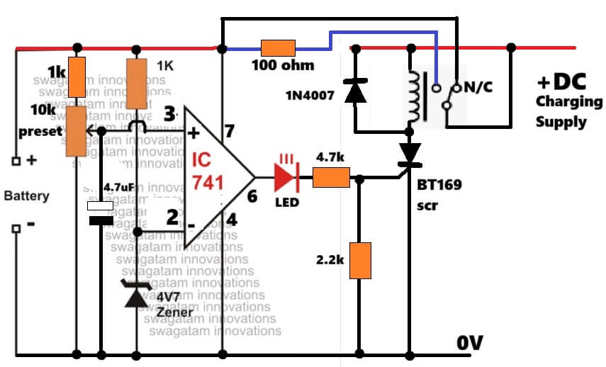
So now starting from the sensing section, the 10k preset together with two 1k resistors samples battery voltage and feeds it into pin number 3 of IC 741, which is the non-inverting input side.

Preset is adjusted for the exact full battery voltage level which we want the circuit to detect.

That 4.7uF capacitor helps calm noise a bit, otherwise relay may chatter randomly.

Pin number 2 gets fixed reference voltage from the 4V zener diode, so now op amp keeps comparing both sides continuously.

At pin 2 there is fixed reference.

At pin 3 there is battery sample voltage.

As long as battery voltage stays lower than preset level then pin 3 voltage also stays lower than pin 2, therefore output pin 6 remains low.

Since output stays low, LED remains OFF, SCR remains OFF, and relay also stays inactive.

Now see relay contact carefully, charging supply goes through the N/C contact of relay.

Since relay is OFF initially then N/C contact stays connected, so charging current reaches battery normally and charging keeps happening.

Now when battery voltage slowly rises during charging then voltage at pin 3 also rises slowly.

The moment pin 3 voltage becomes slightly higher than pin 2 reference, IC output instantly goes high.

That high output now does three things together.

LED turns ON first, which shows full charge condition.

Then high signal passes through LED and 4.7k resistor into gate of BT169 SCR, and SCR switches ON immediately.

Once SCR conducts then current starts flowing through relay coil, from positive supply through relay coil then SCR and finally ground.

So now relay energizes.

This is where the clever part comes.

Relay Latching Feature with SCR

When relay energizes, relay contact shifts away from N/C point, therefore main charging line disconnects from battery and charging stops immediately.

But relay contact arrangement also keeps supplying power to relay coil after switching, so now even if op amp output fluctuates slightly afterward then SCR and relay still remain latched ON.

That is very important because relay chattering near cutoff voltage gets stopped.

Relay stays locked like that until charging supply is removed manually.

Trickle Charging Feature

Now coming to the trickle charging side, even after main charging path disconnects, battery is not completely separated from charger.

One 100 ohm resistor still remains connected between charger positive and battery positive, therefore a very small current keeps flowing into battery continuously.

That small current works like trickle charging and helps compensate battery self discharge.

Since resistor value is fairly high, current stays small and safe.

For example if charger voltage is 15V and battery voltage is 14V then current becomes roughly around 10mA.

Now we see the diode connected across relay coil.

That 1N4007 diode acts like flyback protection diode.

Whenever relay switches OFF then relay coil produces reverse voltage spike, so diode absorbs it and protects SCR, IC and LED from damage.

One big advantage of this circuit is the SCR latch system, because cutoff becomes stable and relay does not oscillate near threshold voltage like ordinary relay cut off circuits.

Important Note

One practical point also here, IC 741 was originally designed for dual supply operation, therefore modern op amps like LM358 or LM393 work much better on single supply 12V battery systems.

These ICs give more reliable switching performance.

Still the old 741 version can also work reasonably well for basic battery charger applications.

Sources

  • academia.edu
  • st.com

You'll also like:

  • wirelessHigh Current Wireless Battery Charger Circuit
  • 100V to 450V Solar Battery Charger Circuit with Automatic cut-off using MOSFET
  • battery capacity testerPrecise Battery Capacity Tester Circuit – Backup Time Tester
  • lowbatteryindicatorcircuit 2Low Battery Indicator Circuit Using Two Transistors Only

Filed Under: Battery Charger Circuits Tagged With: Automatic, Battery, Charging, Full, Latching, Trickle

About Swagatam

I am an electronics engineer and doing practical hands-on work from more than 15 years now. Building real circuits, testing them and also making PCB layouts by myself. I really love doing all these things like inventing something new, designing electronics and also helping other people like hobby guys who want to make their own cool circuits at home.

And that is the main reason why I started this website homemade-circuits.com, to share different types of circuit ideas..

If you are having any kind of doubt or question related to circuits then just write down your question in the comment box below, I am like always checking, so I guarantee I will reply you for sure!

Previous Post: « Simple AM Radio Receiver using IC TA7642
Next Post: Simple H-Bridge Circuits Using BJTs and MOSFETs | No Need of Driver ICs »

Reader Interactions

Questions & Answers

Total Posts: 2
Newest Oldest
Ramin
September 28, 2026 • 3 days ago #212735

Hello and good day, everyone!

“First, I would like to congratulate you and extend my heartfelt appreciation to your strong and successful team. I was hoping you could assist me in designing a circuit that cuts off the power in a mobile phone charging system based on current monitoring rather than voltage monitoring. Put simply, I want the power supply to be disconnected when the battery reaches 100%, but the analysis should be triggered by current sensing rather than detecting voltage drops.

I have reviewed your previous designs in this area, but they all operate primarily based on voltage drops. Additionally, in one of your articles, you implemented a post-cutoff trickle charging system, which was excellent. If possible, I would be extremely grateful if you could design and explain this circuit for both scenarios (full cutoff and trickle charge after cutoff).”

Reply
SwagatamAdmin
September 29, 2026 • 2 days ago #212755

Hi, thanks very much for your kind words!
For current triggered charging cut off, you can refer to the following post:
https://www.homemade-circuits.com/battery-current-indicator-circuit/

Reply

Need Help? Please Leave a Comment! We value your input—Kindly keep it relevant to the above topic! Cancel reply

Your email address will not be published. Required fields are marked *

Primary Sidebar

My YouTube Channel

Circuit Simulator: Draw and Simulate Schematics

circuit simulator image

Categories

  • Arduino Projects (95)
  • Audio and Amplifier Projects (134)
  • Automation Projects (18)
  • Automobile Electronics (104)
  • Battery Charger Circuits (90)
  • Datasheets and Components (109)
  • Electronics Theory (151)
  • Energy from Magnets and Earth (43)
  • Games and Sports Projects (11)
  • Grid and 3-Phase (20)
  • Health related Projects (27)
  • Home Electrical Circuits (13)
  • Indicator Circuits (16)
  • Inverter Circuits (98)
  • Lamps and Lights (161)
  • Meters and Testers (72)
  • Mini Projects (28)
  • Motor Controller (68)
  • Oscillator Circuits (30)
  • Pets and Pests (15)
  • Power Supply Circuits (91)
  • Remote Control Circuits (50)
  • Security and Alarm (65)
  • Sensors and Detectors (107)
  • SMPS and Converters (46)
  • Solar Controller Circuits (62)
  • Temperature Controllers (44)
  • Timer and Delay Relay (51)
  • Voltage Control and Protection (44)
  • Water Controller (37)
  • Wireless Circuits (31)

Subscribe to get New Circuits in your Email

Other Links

  • Privacy Policy
  • Cookie Policy
  • Disclaimer
  • Copyright
  • Videos
  • Sitemap

People also Search

555 Circuits | 741 Circuits | LM324 Circuits | LM338 Circuits | 4017 Circuits | Ultrasonic Projects | SMPS Projects | Christmas Projects | MOSFETs | Radio Circuits | Laser Circuits | PIR Projects |

Recent Comments

  • Swagatam on DC to DC Converter Circuits using SG3524 [Buck, Boost Designs]
  • Swagatam on 3 Best Joule Thief Circuits
  • Swagatam on EGS002 Datasheet, Circuit Diagram Explained
  • Swagatam on Vehicle Parking Lot Counter Circuit
  • Swagatam on Smart Emergency Lamp Circuit with Maximum Features

Social Profiles

  • Twitter
  • YouTube
  • Instagram
  • Pinterest
  • My Facebook-Page
  • Stack Exchange
  • Linkedin

Calculators

  • ZVS Induction Heater + Tank Calculator Tool
  • Zener Diode Calculator
  • Wire Current and Thickness Calculator (Ampacity Calculator)
  • Voltage Divider Calculator
  • Transistor Base Resistor Calculator
  • Transistor Astable Multivibrator Calculator
  • TL431 Calculator
  • Solar Panel, Inverter, Battery Calculator
  • Ferrite Core Air Gap Calculator Tool
  • Parallel MOSFET Calculator Tool: How to Connect MOSFETs in Parallel Safely
  • LC Resonance Calculator for EV Battery Charger Circuits
  • LED String Series Resistor Calculator
  • PFC (Power Factor Correction) Calculator Tool: 3kW
  • Passive Power Factor Correction (PFC) Calculator
  • LM567 IC Calculator Tool
  • SMPS Flyback Boost Converter Calculator
  • Shunt Resistor Calculator for Ammeters
  • SCR and Triac Gate Resistor Calculator
  • Battery Back up Time Calculator
  • Boost Converter Calculator (Non-Isolated)
  • Bootstrap Capacitor Calculator
  • Buck Converter Calculator
  • Buck-Boost Converter Calculator
  • Capacitance Reactance Calculator
  • DCM Flyback Transformer & Wire Gauge Wire Size Calculator Tool
  • Filter Capacitor Calculator
  • IC 4047 Calculator (Frequency and PWM)
  • IC 4060 Calculator
  • IC 555 Astable Calculator
  • IC 555 Monostable Calculator
  • IC SG3525, SG3524 Calculator
  • Inductance Calculator
  • Induction Heater Inductor and Resonant Frequency Calculator
  • Induction Heater Work Coil Calculator
  • Inverter LC Filter Calculator
  • LC Resonance Calculator
  • LED Current Calculator
  • LM317, LM338, LM396 Calculator
  • NAND/NOT Gate RC Values Calculator
  • NOT, NAND Gate Frequency Calculator
  • Notch Filter Calculator Tool
  • Ohm’s Law Calculator
  • Phase Angle Phase Shift Calculator
  • Power Factor (PF) Calculator
  • RC Filter Calculator
  • Reactance Calculator
  • Sine Table Calculator for SPWM Arduino Code
  • Small Signal Transistor(BJT) and Diode Quick Datasheet
  • SMPS Calculator for Toroidal Ferrite Transformers
  • SMPS Flyback Transformer Calculator – Design by Target Duty Cycle
  • TL431 Calculator
  • Op-Amp Hysteresis Resistor Calculator

© 2026 · Swagatam Innovations