We see this radio circuit is very basic, not too many parts, but still it works. This circuit shows how a full MW radio can be made with very few parts. The main part is TA7642 which already has RF amplifier, detector, AGC inside, so we do not need to build all that outside.
Main Features
Even though it is small setup, still it can catch nearby AM stations and you can hear in small headphone, not loud but clear enough.
Main things we notice is it has very less parts, runs from 1.5V battery, detection already inside IC and if we want then we add transistor for more sound.
Circuit Diagram
RF Tuning Section (L1 + C2)
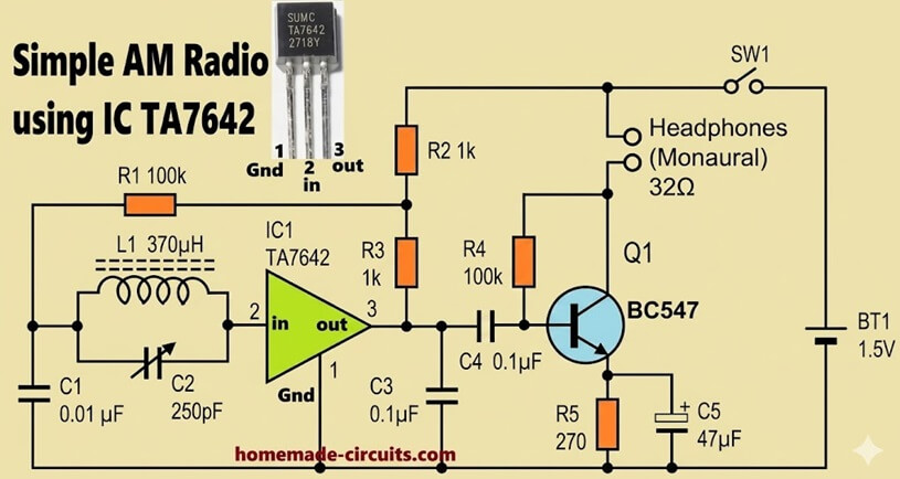
Now for tuning part, we have L1 = 370µH and C2 = 250pF variable, these two together form resonant circuit, which means they select frequency.
Formula is:
f = 1 / (2 * π * √(L1 * C2))
So when you rotate C2 then frequency shifts, so frequency move across 530 kHz to 1600 kHz band.
C1 = 0.01µF is there, it helps bypass RF noise and keeps tuning stable. R1 = 100k gives bias to input, which helps IC behave properly.
Detector and RF Stage (TA7642)
Now signal goes into TA7642 pin 2 which is RF input, inside it amplifies and also demodulates, so audio comes out from pin 3.
Pin 1 is ground, so simple is connection.
Output Filtering
After that we see R3 = 1k and C3 = 0.1µF. These help clean output, by removing unwanted RF parts. Next C4 = 0.1µF passes only audio forward, blocks DC.
Audio Amplifier (Q1 BC547)
Because the IC output is weak, so we use transistor stage Q1 = BC547 with R4 = 100k, R5 = 270 ohm, and C5 = 47µF.
Audio from IC goes to base through C4, R4 gives bias, transistor amplifies and C5 improves gain by bypassing AC at emitter, so sound becomes a bit stronger.
Output (Headphones)
Output goes to 32 ohm headphone. This is important because if you use high impedance then sound will be very low, almost nothing.
Power Supply
Power side is just BT1 = 1.5V battery, SW1 switch, circuit runs fine at low voltage, no need big supply.
Bias Network
R2 = 1k is also there, it gives proper bias to the IC. so it stays stable and does not behave oddly.
Working Flow
Now for working, we see antenna connected to L1 catches signals from air, then L1 and C2 pick one station, that RF goes into IC. Then the IC amplifies and extracts audio, then transistor boosts it, then headphone converts to sound, that's all.
Coil Construction
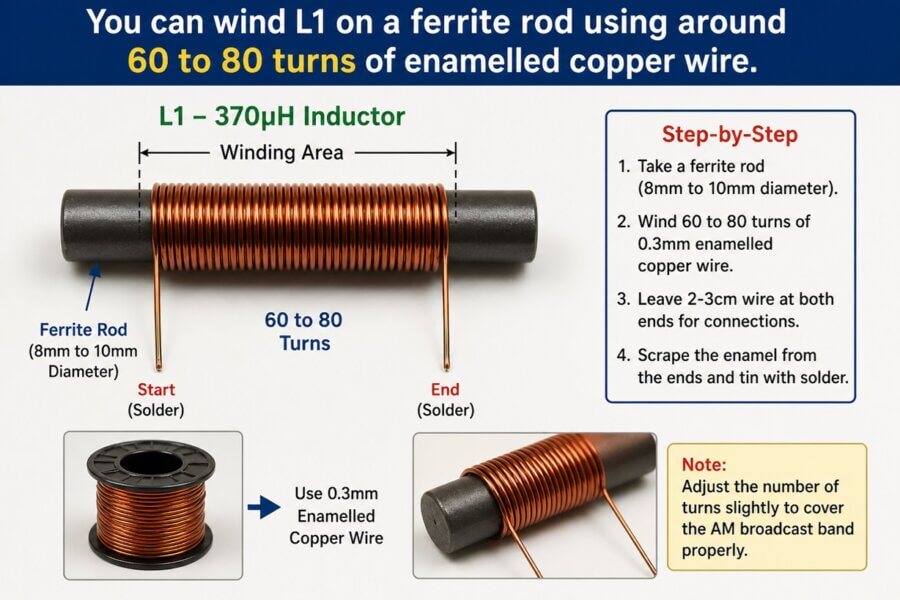
Coil part is important, L1 = 370µH. We make using ferrite rod, around 8mm to 10mm, then wind 60 to 80 turns of 0.3mm wire. If tuning is off then we adjust turns a little, then it settles.
If coil is not proper then sensitivity drops, tuning becomes bad, so this part we do carefully.
Antenna and Ground
For antenna we use long wire, maybe 2 to 5 meters, keep circuit away from noisy devices. And if ground is good then reception improves a lot.
Important Notes
Important things, do not give more than 1.5V because TA7642 is sensitive, wiring should be short, capacitor quality should be good, transistor pins must be correct, and use only 32 ohm headphone.
Limitations
Limitations are there, it works best for strong stations, audio is low so speaker cannot be driven directly, and tuning is manual, no scale.
Possible Improvements
If you want better, then you can add LM386 for speaker, also add tuning dial, or RF preamp if signals are weak.
Conclusion
So now overall, this small circuit shows how radio works, with very few parts. It is good for learning, and if coil and antenna are proper then sound comes clear for nearby stations.


Need Help? Please Leave a Comment! We value your input—Kindly keep it relevant to the above topic!