A water level indicator is an electronic circuit which indicates the various levels of water inside a tank. This happens when rising or dropping water levels come in contact with the respective water sensors arranged step wise inside the water tank at different depths.
In this post I have explained 2 interesting ways to make simple water level indicator circuits using transistors, CMOS NOT Gates and some LEDs, the later section of the articles also discusses how to upgrade the circuit with a relay.
Circuit Objective
There are many posts in this blog which essentially explain water level controller circuits, with the specific intentions of switching the involved motor pump when the tank fills up.
However there are folks who just require an indication of the different levels of water in the tank rather than have an automatic shut off facility.
The switching OFF of the motor is preferred to be carried out manually, which is considered more reliable and safe by them.
For a Wireless Water Level Indicator you can Refer to This Article
1) Using Transistors
We know that undistilled water conducts electricity, although with some resistance. The resistance may be anywhere from 100K to 500K, depending on the purity level of the water. This property can be effectively used for switching transistors ON/OFF.
We use this characteristic of water to switch the base of a series of BJTs sequentially as the water level goes up and down across the sensors attached with the respective transistor bases.
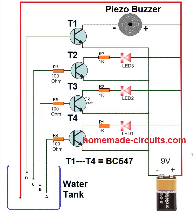
A simple circuit for this can be visualized below:
Video Illustration
The idea is as simple as it can be. The positive terminal of the supply can be seen immersed at the lowest level of the tank, so that water is in contact with this positive even at the lowest level. The bases of the respective transistors are arranged sequentially across the water tank depth, such that when the water fills the tank, it sequentially connects the positive supply with the relevant BJT bases through the rising water level.
When this happens the transistors begin getting biased one by one, illuminating the collector LEDs in the same sequence. When the water reaches the full level, the buzzer is immediately sounded by the topmost BC547.
This helps the user to get a clear idea of the water level, and also when the water has reached the overflowing level.
Parts List
All resistors are 1/4 watt 5%
- 1K = 3 nos
- 100 Ohm = 3 nos
- BC547 = 3 nos
- Piezo Buzzer = 1 no
- RED LEDs = 3 nos
2) Using CMOS NOT Gates
The proposed water level circuit idea is specifically suited for the above type of readers who are satisfied with the indications only and want to do the shutting part of the motor manually as per the readings of the indicator and as per the desired water levels in the tank.
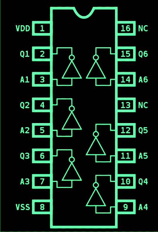
- The circuit presented here is again super simple to build, involving only a single IC 4049 for the intended applications.
- The IC as we all know have six NOT gates, these gates are simple inverters, meaning they will invert any voltage level at their input pins to exactly the opposite level at their output pin.
- So if a positive is applied to the input, the output would instantly produce a negative and vice versa.
- The high input impedance of CMOS gates makes sure that potential even with very low currents are suitably sensed and interpreted by them.
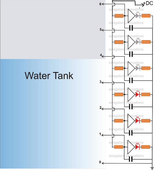
- The idea is simple, the ground or the negative voltage (point 0 in the figure) is held at the bottom most part of the tank, such that the water reaches this point first up when it starts filling.
- As the water level goes higher, it subsequently comes in contact with the inputs of the NOT gates arranged serially upwards.
- The negative voltage stationed at the bottom of the tank leaks through the water and comes in contact with the relevant inputs of the gates.
- This negative potential applied at the subsequent inputs of the gates means a production of an opposite voltage, that is a positive potential at their outputs, that's what exactly happens.
- The positive voltage thus generated lights up the concerned LEDs, indicating which input of the gate at what level has come in contact with the rising water level.
- The sensor wire terminals from the circuit in the form of the points 0 to 6 may be arranged over a non conducting stick made up of plastic with brass screw heads fitted as the sensor termination.
- The LED illuminations give a direct indication of the water levels, as these are stationed with calibrated positions in the tank (see circuit diagram)
The pin out diagram of the IC
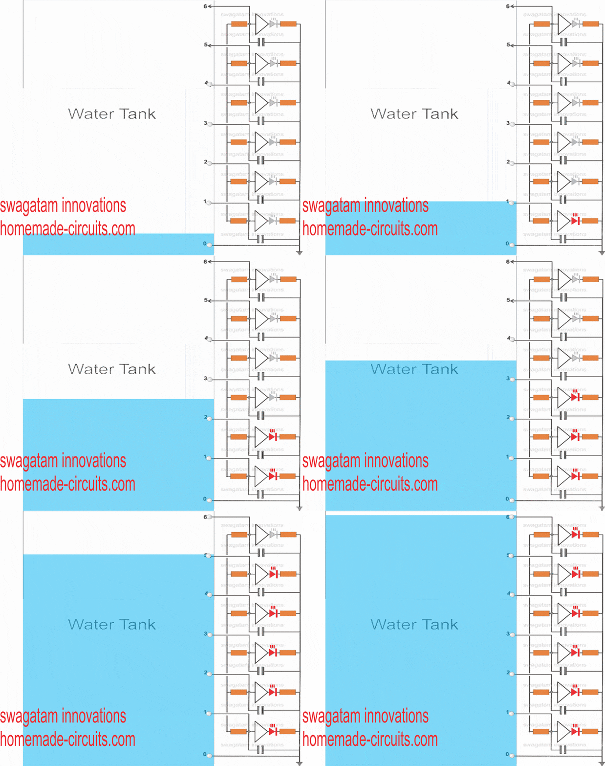
Simulation: A rough simulation of the discussed water level indicator circuit is shown below. We can see how the LEDs light up sequentially in response to the increasing water level coming in contact with the respective sensor points inside the water tank
Part List.
- All LED resistors are 470 Ohms,
- All gate input resistors are 2M2
- All capacitors are 0.1 disc ceramic.
- All the gates are CMOS NOT Gates
- All LEDs are red 5mm, or as preferred by the maker.
Practical Tested Prototype
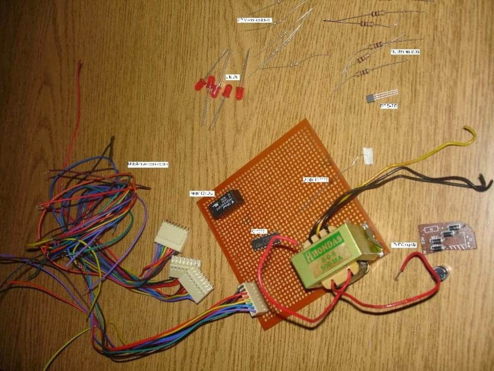
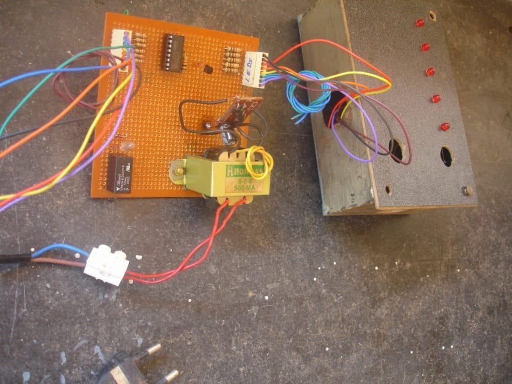
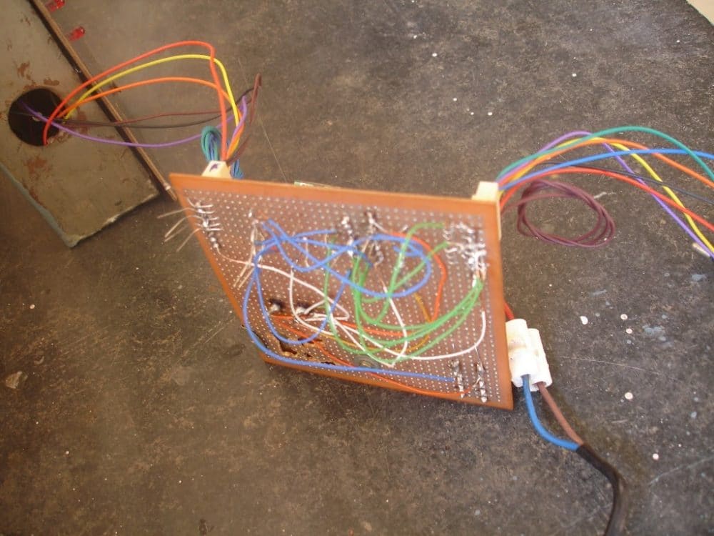
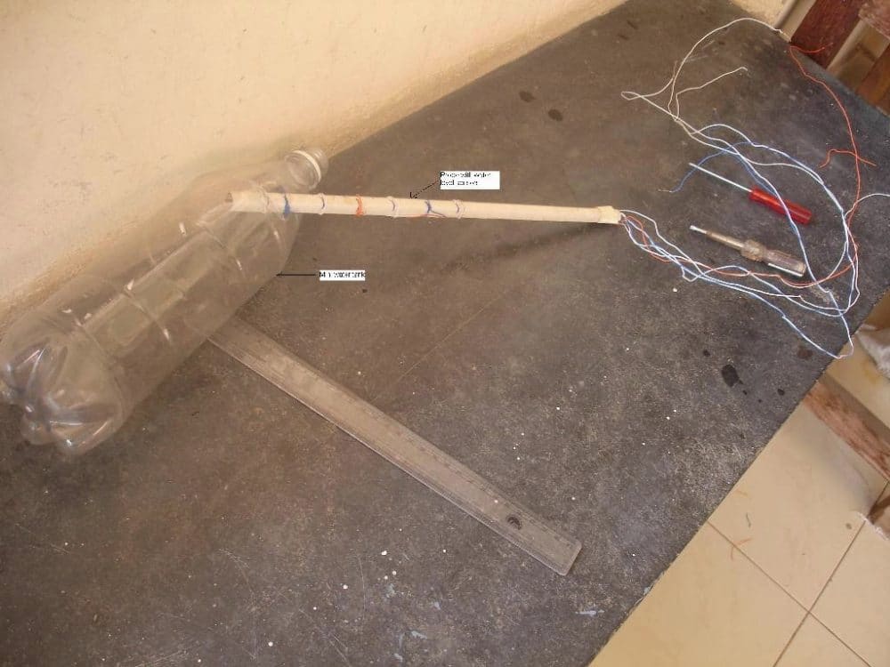
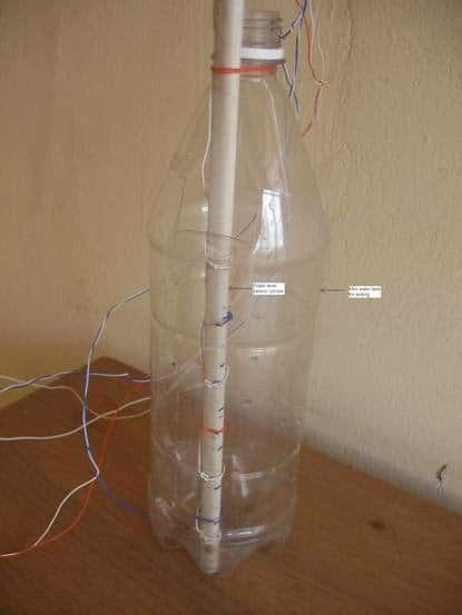
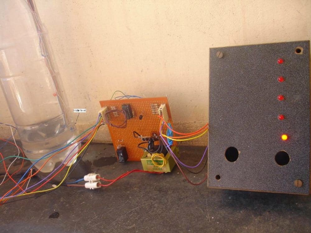
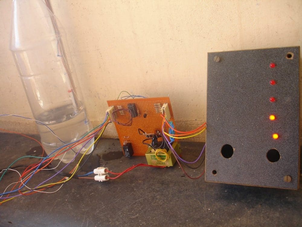
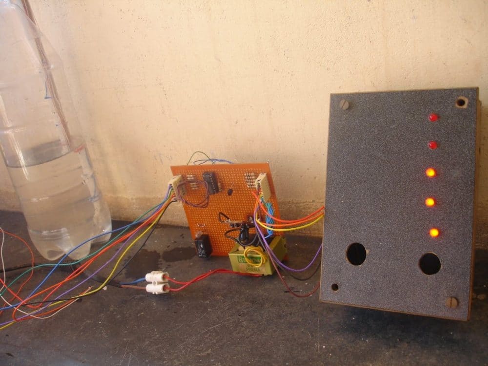
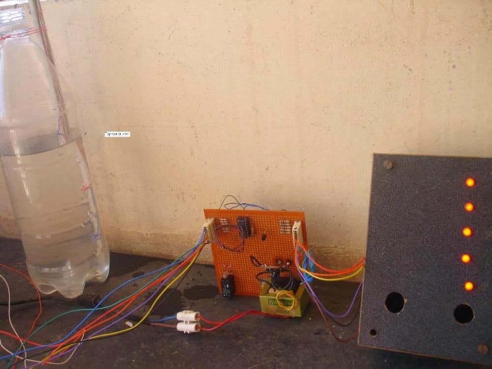
The above circuit was successfully built and tested by Mr. E.Rama Murthy who is one of the regular and dedicated readers of this blog. The following pictures of the built prototype were sent by him, let's investigate the results closely.



Questions & Answers
Hi Swagatham
This is Vee I want to make a water level switch which would switch on a relay and in turn switch on a solenoid to open a water line to fill a small tank when the level goes down, How many amps would a reed switch handle to activate a 5 volt relay
Please send me the circuit to my email also,
Thank you Swagatham and all the best & God bless you
Hi Val,
You can get the circuit diagram in the following video:
https://youtu.be/u9xWVH-NENo
A reed switch can easily handle upto 200 mA current, so no problem with the 5 V relay.
Hi sir, I’m using the simple water level indicator circuit with transistors (bc 547) as given in this post. I have added a buzzer as the last stage of sensing at which I will be able to stop the motor manually. But problem is that the sensing wires corrode after some days and buzzer sounds very feeble. I got a float switch but it is ‘Normally Closed’ one. Pls let me know how to use this ‘NC’ float switch using transistor(pnp or npn) for indicating the uppermost level giving a buzzer sound.
Hi Binoj, I guess you are referring to a normally closed (N/C) reed switch? For an N/C reed switch you can try implementing the following transistor configuration:
Ys it’s now perfectly working sir..Great deal with you and your invaluable articles…Thank you ????????
Thanks Binoj, Glad it worked!
Sir please can i have the literature review of the water level indicator?
Victor, I wish I could do it for you, however due to lack of time it is difficult for me to create a literature review at this moment of time.
Can I use 12v dc to this circuit instead of 9v dc shown
To have heigh beep sound what type of buzzer is to be used
yes 12V can be used. A normal piezo buzzer used in automobile flashers will be good enough
In our circuit we have used BC148 npn 220 ohms insted of 100ohm in your circuit. Kindly clarify 12v dc can be given in place of 9v dc as 12v readly available solar battery
Yes 12V can be used without any problems.
Can you tell me why did you put LEDS at collector terminal? And can i put buzzer instead of LED? I don”t understand why transistor is switching mode
Where else do you think LEDs can be put? Collector is the perfect place for the LEDs… Yes you can use buzzer in pace of the LEDs.
I have a question,,,
Can you explain why you put resistance to the base of the transistor and to the collector?
those are current limiting resistors. Base resistor is always required otherwise the transistor will burn due to base overcurrent. The collector resistor is also for the same reasons, for protecting the LED and the transistor both from overcurrent
Hi Swagatam,
may it be possible to replace the metal electrodes as sensing elements, by graphite electrodes, to avoid corrosion problems?
Thank you in advance, and best regards
Alfredo
Thank you Alfredo, that’s a good idea, and can be tried.
what is m2m and why is capacitors used??
Hello, i want to ask that how is the circuit of water level indicator sensor with alarm using LDR component.
Why do you want to use an LDR?
Sir I need another 2 indications to the same circuit
1) water filling to tank from municipal source
2) water from under water source.
We should know which source of water was filling to the water tank by “Led” indication this should be by same circuit was it possible
Manjunath, it can be very easily implemented. Suppose you want the 6th gate to inform you about this, then you can pick one link from the 6th gate input and another link from the ground line and position the end terminals 1 inch apart and place them at the mouth of the source. So when the water arrives it will connect these terminals and the respective IC gate will illuminate the LED providing the required indications.
Sir,
but sixth gate is already used for water level “full” indication.
Without interrupting, the above indicators, can I use sixth gate as another indicator for ground water inflow indicator to the water tank. By adding another component that would work as 6th gate as water level full indicator ( as shown in diagram) and also ground water inflow indicator
Hi Manjunath, I just gave an example of the 6th gate….if you actually use the 6th gate for indicating the water source then it will illuminate in advance if the water comes from that source and will become ineffective as the full level indicator.
Instead it’s better to employ a separate PNP BC557 Darlington based network, and use it for sensing water from the source through its base, and the ground line.
please advice value of R 13 in circuit diagram with pump control. in circuit diagram you show 13 resistors but in pictures only show 12 resistors. R1 TO R6 = 2M2 and R7 TO R12 = 1K. What is value of R13 ?
R13 can be a 10K 1/4 watt resistor, for the transistor base
Good day. I would like to know if i can make sensor f and o common, will that turn off the relay when water level drops below sensor fo? ( sensor f and o is one sensor.) and will the rest of the circuit function normal?
Hi Ian, that may not be possible without some elaborate modifications, I have updated the modified design for enabling this operation, you can find the upgraded design at the bottom section of the article. This will allow the motor to switch ON only when the water level reaches point “F” and switch OFF when it drops below point “D”
Good day.
Thank you sir for your quick response, time and effort to modify this circuit for my kneed, i rely appreciate it.
I have a 45 L reservoir filled by hand with water and a submersible pump and aquarium heater inside the reservoir. The heater stays on permanently and regulate the water temperature with a thermostat, the pump is controlled through a timer at regular intervals of two hours off and fifteen minutes on. The water that gets pumped out of my reservoir into a separate hydroponics system, finally flows back into my reservoir through gravity, but eventually the plants use some of the water and the water level in my reservoir drops and needs topping up. The hydroponics system cannot over fill because there is a extra drain pipe, placed at the correct level, draining back to reservoir. This hydroponics system is called flood and drain.
I want to use the water level circuit to indicate the water level in my reservoir without opening the reservoir and to protected my pump and heater from running dry or switch off power to pump and heater below sensor D for example. With your new circuit i can clearly see where to incorporate the two transistors to control the relay for switching power to pump and heater. The SCR, in my case, is not needed so i can use N1 gate to turn on an extra led placed at the correct place for a more accurate water level indicator and include a buzzer for audio warning when water level drops to low with the extra gate available now.
I hope my explanation of my requirements makes sense to you, but one thing is for sure, i know now how to switch what ever at what ever level with this circuit.
Please correct my if i am wrong with reading and understanding your new circuit. Circuit must indicate water level of reservoir and audio alarm at sensor D and turn of power to pump and heater at sensor E and now extra sensor F gained from not needed SCR.
Thank you Sir.
Thanks for the detailed explanation,
However I think the SCR is crucial here, otherwise it would be same as the earlier circuit and the relay would keep toggling ON/OFF in response to the upper water level.
The SCR ensures that once the motor is initiated with the top level water, it doesn’t stop until the water level has reached below the “D” point.
So the SCR along with the two transistors are crucial in the last modified design.
Thank you sir.
Dear sir,
I made a water level controller with your help but the problem arises with corrosion at probes. so I need your help and want to know about such a material that do not corode.
One thing I want to mention that I have used a water level controller device of skylet company, its sensor do not corode over long period of use so I want to know what type material they use?
Thanks.
Dear Rakesh, corrosion can be avoided by using brass terminals coated with good quality solder, however it is not the corrosion we are worried about, rather it is the formation of a non conductive layer over terminals which can create problems. That can be prevented by a applying a push-pull kind of supply to the terminals.
An alternative long term solution would be to use separate ground terminals for each of the sensing terminals, instead of a single ground at the bottom of the tank.
for enabling a corrosion operation you can probably try the last updated design as shown in the following article
https://www.homemade-circuits.com/anti-corrosion-probes-for-water-level/
Dear sir,
Please tell me why 0.1 disc capacitor is used in the above circuit. Will it work with out the capacitors ?
Thank you .
Nataraj, the 0.1uF are positioned to prevent stray disturbances affecting the gate input pins, and to prevent false LED illumination.
If the sensing wires are small then the capacitor can be avoided otherwise it is recommended to include those capacitors.
Ok thank you sir.
sir as the wire immersed in water . later on a thick white layer formed arround the cutted part of wire , and it stoped working , so what should i do to work that for long period.
thak you sir
manjunath, did you tin the terminals with ample solder metal?? make a ball of solder at the ends
make sure to use good quality 60/40 solder and then check the response