In this post I have explained a few interesting methods of constructing anti-corrosion probes for water level sensor and controller circuits by using alternating supply across the probes.
Using Bridge Rectifiers (New Update)
This simple anti-corrosion probe idea using bridge rectifiers happened to strike me recently and I decided to post it here for you all.
The complete circuit diagram is shown below.
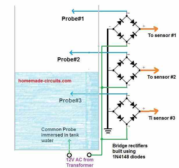
The idea is actually very simple but very effective and cheap. A bridge rectifier circuit using 1N4148 diodes can be seen associated with each of the sensing probes.
One of the AC inputs of the bridge rectifiers are used as anti-corrosion probes for sensing the water level inside the tank, while the other AC input connections are made common for applying the 12V AC.
The other 12V AC terminal is used as the common terminal immersed inside the tank water.
The alternating current from this common wire passes through the water and hit the probe#1, probe#2 and probe#3 sequentially as the water climbs up in the tank.
This causes the AC voltage to pass through the respective bridge rectifiers and convert into DC across the relevant bridge rectifier outputs.
These DC outputs are then sensed by the attached electronic water level sensor circuit for switching ON or OFF the relevant relays or transistors.
Since an AC is used across the input probes, the probes remain perfectly immune to corrosion and thus the circuit works as an ideal anti-corrosion water level sensor circuit.
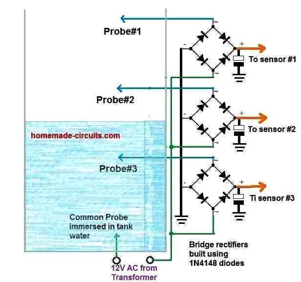
NOTE: PLEASE REMEMBER TO PUT FILTER CAPACITORS ACROSS THE BRIDGE OUTPUTS AND GROUND, TO FILTER THE AC TO PURE DC, AS SHOWN BELOW:
Using OR Gates
How it Works
So I have explained the above concept used for designing this anti-corrosion probe circuit for water level sensors and controllers.
Corrosion in water level sensor probes take place due to DC supply which is normally used for triggering the probes through water. This is aggravated by the process of minor electrolysis across the probe terminals which in the long term usage results in formation of layers of chemicals an minerals, gradually inhibiting efficient working of the probes and affecting the water sensing ability of the circuit.
To remedy this an AC supply is recommended so that the process of electrolysis is unable to develop across the probes due to the constant flipping of the supply polarity across the probes through the alternating nature of the supply.
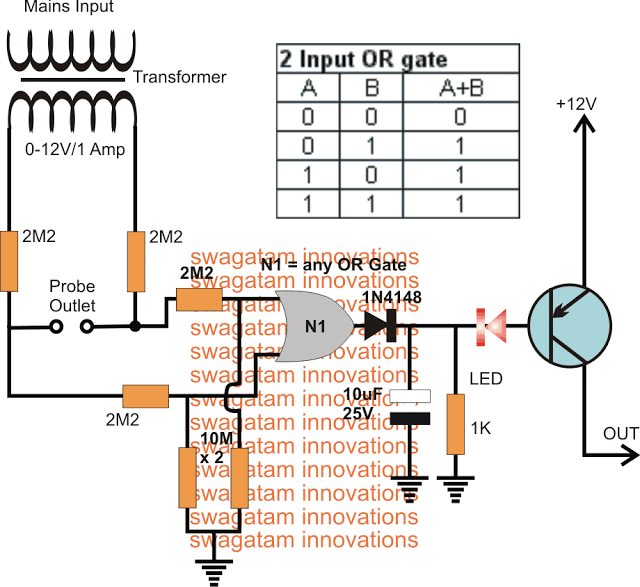
In the design presented above, the AC supply is derived from a 12V transformer, via a couple of high value resistors for dropping the current across the probes.
The supply is carried forward to the inputs of an "OR" gate which specifically deals with this AC and produces the relevant output depending on whether water is present across the probes or not.
In the absence of water the applied AC generates alternately changing potentials across the two input pins of the OR gate. As per the truth table of the OR gate, a 0 and 1 or 1 and 0 on its inputs correspondingly creates an output of logic 1. This implies that while the alternate switching is applied over the two inputs of the OR gate, causes its output to consistently be at a logic 1.
Now if water happens to bridge the probe points, it instantly causes a relative short across the points causing the AC to disappear at the inputs of the OR gate.
In this situation both the inputs of the OR gate is held at logic 0, which causes its output to revert from logic 1 to a logic 0.
The above action switches ON the PNP transistor enabling the output to trigger the intended load such as a relay or an LED.
More number of gates could be employed with parallel probes points at different depths of the water tank in order to sense the various levels of the water if required, for building a multi water level anti-corrosion sensor probe circuit
The OR gate IC could be a IC 4071 or any other similar.
Another Design using IC 4093 NAND Gates
The impact of electrolytic corrosion between the liquid and the metallic sensors is an unpleasant disadvantage of several liquid level sensors. Metal electrodes are susceptible to corrosion, which results in a loss of efficiency (lower conductivity), necessitating their replacement at regular intervals.
A way to solve this is to guarantee that the sensor electrodes have an AC voltage instead of a DC potential. The electrolytic reaction is greatly slowed by the continuous change of electrode polarity, resulting in a significant reduction in corrosion.
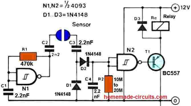
The level sensor's fundamental working is relatively basic. An oscillator is formed by the circuit that surrounds N1. C4 will be charged up through the AC coupling capacitors (C2 and C3) and the diodes as soon as the two sensors are submerged in water, and the output of N2 would be pulled low so that the relay will be activated after a brief period.
As an example, the relay could be used to activate a pump, which then regulates the liquid level. Once conductive link across the two sensors leads is removed, C4 discharges through R2, causing N2's output to become high and the relay to turn off.
Simple Corrosion Free Water Level Sensor Circuit
The following figure a possible simpler method of creating a corrosion free water level sensing terminals.
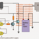
NOTE: Please connect a 100K resistor between base/collector of BC557 transistor, otherwise it will not respond to the base 100 Hz switching
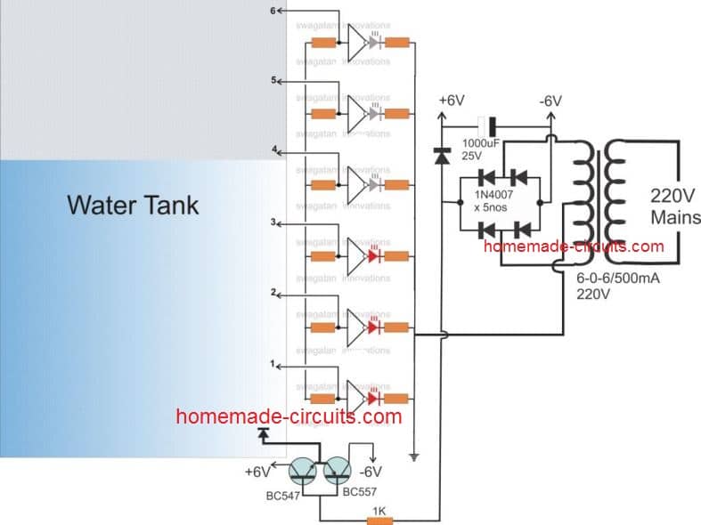
In the diagram we can see that the reference ground terminal at the bottom of the tank is supplied with an alternating +/- 6V instead of a normal DC. This forces the other terminals to conduct in a push-pull manner with the reference to this base terminal and this hopefully prevent corrosion from developing across the connected water level sensing terminals.
Using Opto Coupler
A perfect corrosion free water sensing probe can be built using an opto-coupler stage between the probe and the controller circuit as shown below:
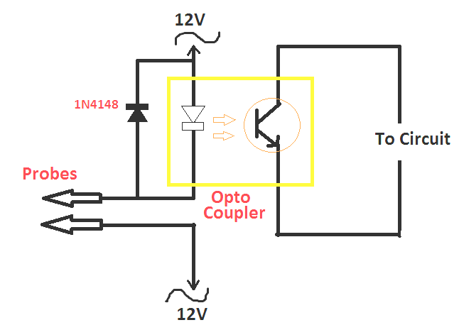
As can be seen the probes are applied with a 12 V AC through the LED of an opto-coupler, and a reverse diode. One half AC cycles pass through the water and the probes by means of the opto LED, which triggers the controller circuit, while the other half AC cycle flows through the reverse diode.
The continuously reversing cycles of the AC ensures that no electrolysis of water is able to happen across the probes, which prevents any form of oxidation or corrosion development over the probes.

Questions & Answers
Hi Swagatam,
firstly wonderful article, can you. please help to add a debouncing circuit as while the water is touching the sensor there is a wave / ripple causing the motor to turn on / off continiusly
Thank you Chandrashekhar,
You can easily control the motor stuttering at the water thresholds simply by adding a 470uF or bigger capacitor right across the relay coil terminals, or maybe a 100uF capacitor across the base/emitter of the relay driver transistor.
Please let me know if that helps or not…
hola amigo muchas gracias por los diagramas, son muy interesantes quiero fabricar uno de ellos y pide que se haga un puente con 4 diodos 1n4148, la pregunta es haya como hacerlo con un puente directo de 1 amp. o es necesario hacer con los diodos 1n4148 gracias por la respuesta
You are welcome Fantasma,
I would recommend using 1N4148 diodes since they are sensitive and will respond even to very low current inputs.
Dear Mr Swagatam, Greetings,Thank you for the information on the construction of water level sensor. Pls Sir I want to know if these circuit can also be used in waterboiler/steam generator to cut off electricity supply to heating element when the water get below a certain level to protect the heating element from damage due running dry when the water level go low
Thank you oderinde, for your interesting question!
Yes, any standard water level controller which can sense current through water can be used for your specific application.
Let me know if you need any further information or help about this application.
Dear Mr Swagatam
Greetings,
Needs your permission to use your ideas of corrosion free probes of my home ???? water control management.
Thanks and Regards
Muhammad Latif Mughal
Hi Muhammad,
You can use the above ideas for your home water control management.
Thanks Sir
Regards
Hye!
Thanks for posting these awesome ideas ????
My comment is on the Opto-Coupler circuit, that of what ampere the 12v transformer is enough for probes?
Thanks Param, the transformer rating can be 500 mA or 1 amp
Greetings..!!!
Dear Swagatham,
Regarding the new update of anti corrosion probe we cant use smd type bridge rectifier module.only 1n4148 bridge.Its so space consuming.better go for one with opto coupler its excellent also total isolation and works fine.Thank you..!!!
With Love
Dr.Sison
Thank You dear Sison,
I appreciate your kind feedback and updates.
All the best to you!
Cheers!
Greetings…!!!!
Hi Dear Swagatham,
Finally find the error in new update of corrosion free water level indicater with 1n4148 bridge.The problom is we have to connect +ve out of bridge to +ve supply of 4049 circuit and _ve output of bridge to triggering pin(probe) of 4049.Then its work fine.anyway Thanks alot for such a super simple idea.Appreciate great effort.
With ❤????????????
Sison.
Thank you Sison, for your valuable update,
However I am afraid that’s not how a bridge rectifier is supposed to work. Did you try placing the probes 1 inch apart in water, and measure the bridge rectifier output with a Dc voltmeter.
You can try the following setup to measure the output from the bridge rectifier. And I think 1N4148 would be more suitable in this setup:
No need for 1 inch..more than one or several inch will work perfect.morover the output voltage is @10volt when using 12v 250 ma transformer.hope you will update the picture(circuit) aaap.
Thank you…Swagatham.
That’s great Sison, thanks for checking!…so i guess the 10 V DC will be enough to trigger ON the 4049 inputs or any other water level controller circuit input.
Greetings..!!!
Dear Swagathem,
This is regarding the new update about anticorrosion probe using the bridge rectifier(4148).But when i connect to existing 4049 water level indicator unfortunately its not working.but when removing new update…its working properly also its work excellent with opto coupler circuit.The idea is so amazing but dont know why its not working.please do needfull and help us the readers.
With..❤❤❤
Sison
Thanks for the update Sison,
Before connecting the bridge rectifier outputs to the 4049 IC inputs did you check how much voltages the bridge rectifier outputs is actuality generating?
Please check the bridge outputs with a DC voltmeter and make sure it generates at least 5 V DC in response to the 12 V AC in water.
Also please make sure the other 12V AC common terminal is positioned as close as possible to the sensor probe terminals inside water. This will help the AC supply to reach the bridge inputs with highest possible power.
Will try and update you soon…
no problem!
When i connect the new update do i need to remove 104 capacitor from 4049 circuit?
You can keep the 0.1uF capacitor at the 4049 gates. No need to remove it.
Greetings…
Dear Swagatham,
Regarding the new update of anti corrosion probe of water level …can i use__smd bridge rectifier module_
instead of making 1n4148 bridge rectifier? And can replace 1n4148 by 1n4007 diode?
With ❤????????
Sison
Hi Sison,
Yes you can use SMD bridge or any other type of rectifier bridge.
You can use 1N4007 instead of 1N4148, but 1N4007 will consume a lot of space.
Greetings…!!!!
Hi Swagatham,
Its so amazing that you introduce further update and simplify the corrosion free probe by bridge rectifiier and 12volt tranaformer…its Really amazing..!!!.Hope this can directly attach to existing water level indicator with 4049 ic from yoir previous circuit.Morover can use 12 v 250 ma transformer?hope this can easly attach to any water level controller too right?
From Kerala with..❤❤❤❤
SISON.C.S
Thank you Sison,
Glad you liked the new concept!
Yes it can be directly attached to 4049 circuit or any other similar water level controller circuit.
The transformer can be any 12V or 6V transformer rated above 50 mA
Greetings
Hi Dear Swagatham,
According to your opto coupler circuit can i connect 12 volt ac directly to water?im using 0..12v 500ma transformer.And the output of transistor emitter paralleling and can use for different switching of various levels on its collector?
Hi Sison,
yes certainly you can do that. Just make sure to add a 1K resistor with the lower connection of the 12V AC so that the diode and the LED can remain safe in an event of an accidental shorting of the probes.
If you parallel the opto couplers, make sure to add a 1N4148 diode individually with each emitter of the opto transistors.
Dear Swagathem,
This circuit working excellent at 12 v ac.appreciate good effort such a desighn.
Sison…????????❤❤
That’s great Sison, thanks for sharing the info!
Dear Swagatam,
The sensors I am dealing with are contact-type water level sensors. I am trying to make probes using optocouplers, but your diagram is unclear. Could you please send me the complete diagram?
Hi Prabhakar,
Can you please tell me what is not clear to you in the last opto-coupler based design??
I am using a 555 timer chip and transistor to operate an automatic water level monitoring circuit with an ac washing machine water valve attached to a garden hose port. The copper wire I am using for the probes for now tend to get a dark deposit on them after sitting in the water. I will remove them and sand the copper smooth again. The circuits I have seen on this page use gates and ac current through the probes to slow down or eliminate the electrolysis that takes place with dc on the probes from pins 2,6, and 8 of the chip. Is there a way to protect the probes without using the gates or ac through the probes?
Adding an AC to the robe can be a lot difficult, and it can make the circuit too complex, you may require optocouplers as shown in the last diagram. I would rather suggest tin plating the copper through a high grade 60/40 solder wire and soldering iron, this will help to keep the contacts corrosion free.
I do have solder that came with my soldering station from Amazon, How am I to know this is a high quality solder as opposed to run of the mill cheap but useable type? The roll says Sn99, and 3cu0.7 and ROHS2.0 that doesn’t tell me about it’s quality.
Normally a good quality solder will be lustrous and shiny, will generate less smoke, melt quickly and sometime they may be scented also….so basically a good quality solder will look silvery and shiny once coated over a desired surface
Hello Swagatam ji,
Nice work !
Does this circuit remains safe if any leakage current occured in water ? such as main pump current/earthing faults or else.(ultimately, reliability also matters)
Thanks Atul,
According to me the probes will not get affected from voltage leakages from the pump or any other external interference. Nevertheless, this can be only confirmed with a practical testing.
My comment is not on THIS opto-coupler circuit but on a similar one. Before I surfed onto your page, I found a water level circuit using a uln2004a Darlington pair IC. The brain power is 12vdc with + on pin 9 and – on pin 8. Pins 1-7 are inputs with a 47k series resistor. 12v + is sensor(s) common lead. Outputs 10-16 go to an LED with series 1k resistor to the 12v +. I substituted the 1k resistors with a 5vdc relay and it worked perfectly. My problem is the corrosion on the sensors. Sensor current was 26 uA
Could I substitute a 24vac xfmr and put a diode-resistor circuit across the input of my sensors to conduct the negative 1/2 cycle? If yes, should I start with a 100k pot and dial it down so that reverse current matches forward current that goes thru sensor input?
Yes you can use 24V AC through a resistor, and add opposite diode across the opto coupler LED. I could not correctly understand the connections that you have explained. I believe the connections should be exactly as given in the last opto couoler diagram.
Thank you, if it works I will draw an exact sketch and send it to you. :-))
Sure, no problem!
hello sir, please provide full schematic of opto coupler ic cicuit, how can i replace with carbon sensor, i am having a three sensor motor on off device.
thanks and regards.
Hello Nitin, you just have to connect a transistor stage at the output of the optocoupler, and a relay at the collector side of the transistor. Also make sure to add a 100uF capacitor across the base/emitter of the transistor.
Regarding the optocoupler variant an RC circuit has to be considered in serial to the probes. The resistor must prevent the diodes from burning at SC of the probes and the capacitor must filter the DC component, as the voltage over the LED and the diode are not symmetrical.
Hi sir,
I have made simple 12v dc powered water
level controller by using BC547. After switch. On the device it works properly. And i found stray volage in my water tank. Kindly suggest how to prevent the stary voltage in my water tank.
Hi Prasanth, at which points did you measure the stray voltage?
Hi sir, thanks for your response. I have not tested by any instrument . But I have inserted my hand in water tank and i felt the electric shock in water. (Note :- i had taken 12volt DC current from normal 12v dc adapter to my circuit)
Hi Prasanth the “shock” feeling may be due to AC mains leaking from the transformer body. Please make sure that you have a good earthing in your mains socket, and connect the transformer iron body with the earthing line…if you are using an SMPS, then connect the negative line of the circuit with the earthing line.