A water level indicator is an electronic circuit which indicates the various levels of water inside a tank. This happens when rising or dropping water levels come in contact with the respective water sensors arranged step wise inside the water tank at different depths.
In this post I have explained 2 interesting ways to make simple water level indicator circuits using transistors, CMOS NOT Gates and some LEDs, the later section of the articles also discusses how to upgrade the circuit with a relay.
Circuit Objective
There are many posts in this blog which essentially explain water level controller circuits, with the specific intentions of switching the involved motor pump when the tank fills up.
However there are folks who just require an indication of the different levels of water in the tank rather than have an automatic shut off facility.
The switching OFF of the motor is preferred to be carried out manually, which is considered more reliable and safe by them.
For a Wireless Water Level Indicator you can Refer to This Article
1) Using Transistors
We know that undistilled water conducts electricity, although with some resistance. The resistance may be anywhere from 100K to 500K, depending on the purity level of the water. This property can be effectively used for switching transistors ON/OFF.
We use this characteristic of water to switch the base of a series of BJTs sequentially as the water level goes up and down across the sensors attached with the respective transistor bases.
A simple circuit for this can be visualized below:
Video Illustration
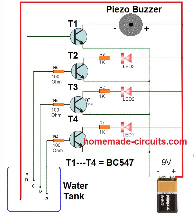
The idea is as simple as it can be. The positive terminal of the supply can be seen immersed at the lowest level of the tank, so that water is in contact with this positive even at the lowest level. The bases of the respective transistors are arranged sequentially across the water tank depth, such that when the water fills the tank, it sequentially connects the positive supply with the relevant BJT bases through the rising water level.
When this happens the transistors begin getting biased one by one, illuminating the collector LEDs in the same sequence. When the water reaches the full level, the buzzer is immediately sounded by the topmost BC547.
This helps the user to get a clear idea of the water level, and also when the water has reached the overflowing level.
Parts List
All resistors are 1/4 watt 5%
- 1K = 3 nos
- 100 Ohm = 3 nos
- BC547 = 3 nos
- Piezo Buzzer = 1 no
- RED LEDs = 3 nos
2) Using CMOS NOT Gates
The proposed water level circuit idea is specifically suited for the above type of readers who are satisfied with the indications only and want to do the shutting part of the motor manually as per the readings of the indicator and as per the desired water levels in the tank.
- The circuit presented here is again super simple to build, involving only a single IC 4049 for the intended applications.
- The IC as we all know have six NOT gates, these gates are simple inverters, meaning they will invert any voltage level at their input pins to exactly the opposite level at their output pin.
- So if a positive is applied to the input, the output would instantly produce a negative and vice versa.
- The high input impedance of CMOS gates makes sure that potential even with very low currents are suitably sensed and interpreted by them.
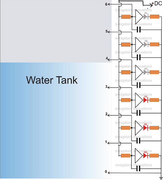
- The idea is simple, the ground or the negative voltage (point 0 in the figure) is held at the bottom most part of the tank, such that the water reaches this point first up when it starts filling.
- As the water level goes higher, it subsequently comes in contact with the inputs of the NOT gates arranged serially upwards.
- The negative voltage stationed at the bottom of the tank leaks through the water and comes in contact with the relevant inputs of the gates.
- This negative potential applied at the subsequent inputs of the gates means a production of an opposite voltage, that is a positive potential at their outputs, that's what exactly happens.
- The positive voltage thus generated lights up the concerned LEDs, indicating which input of the gate at what level has come in contact with the rising water level.
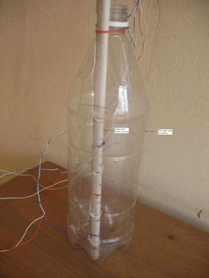
- The sensor wire terminals from the circuit in the form of the points 0 to 6 may be arranged over a non conducting stick made up of plastic with brass screw heads fitted as the sensor termination.
- The LED illuminations give a direct indication of the water levels, as these are stationed with calibrated positions in the tank (see circuit diagram)
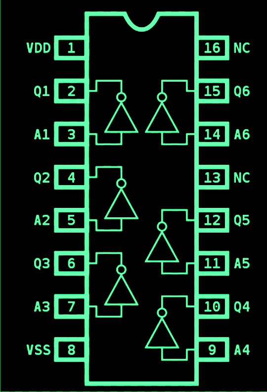
The pin out diagram of the IC
Simulation: A rough simulation of the discussed water level indicator circuit is shown below. We can see how the LEDs light up sequentially in response to the increasing water level coming in contact with the respective sensor points inside the water tank
Part List.
- All LED resistors are 470 Ohms,
- All gate input resistors are 2M2
- All capacitors are 0.1 disc ceramic.
- All the gates are CMOS NOT Gates
- All LEDs are red 5mm, or as preferred by the maker.
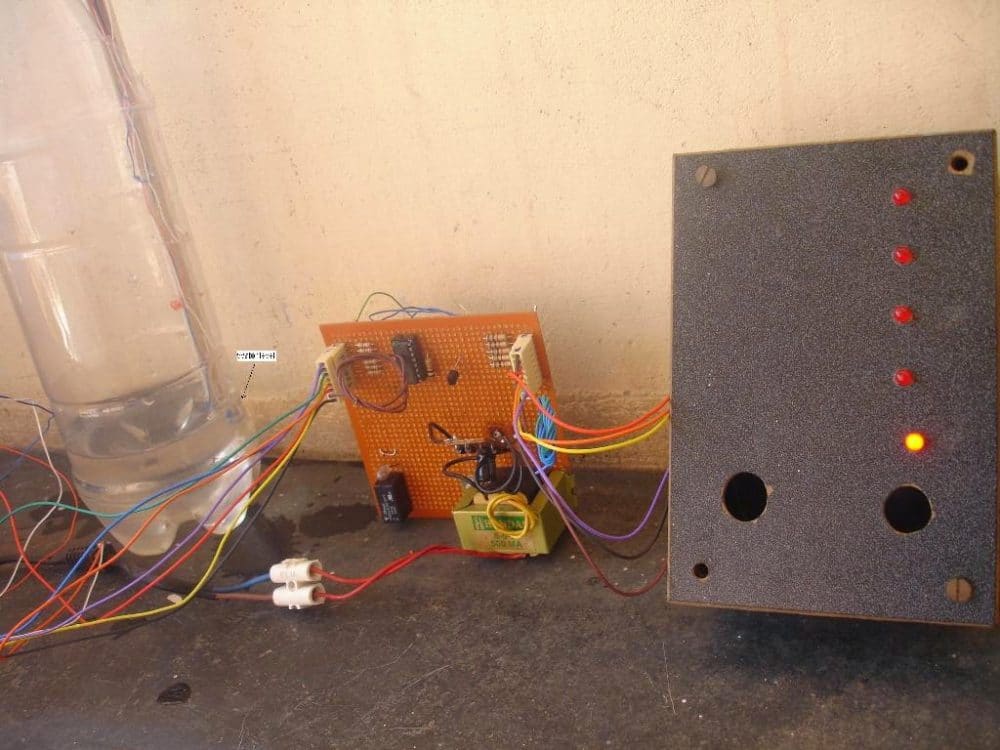
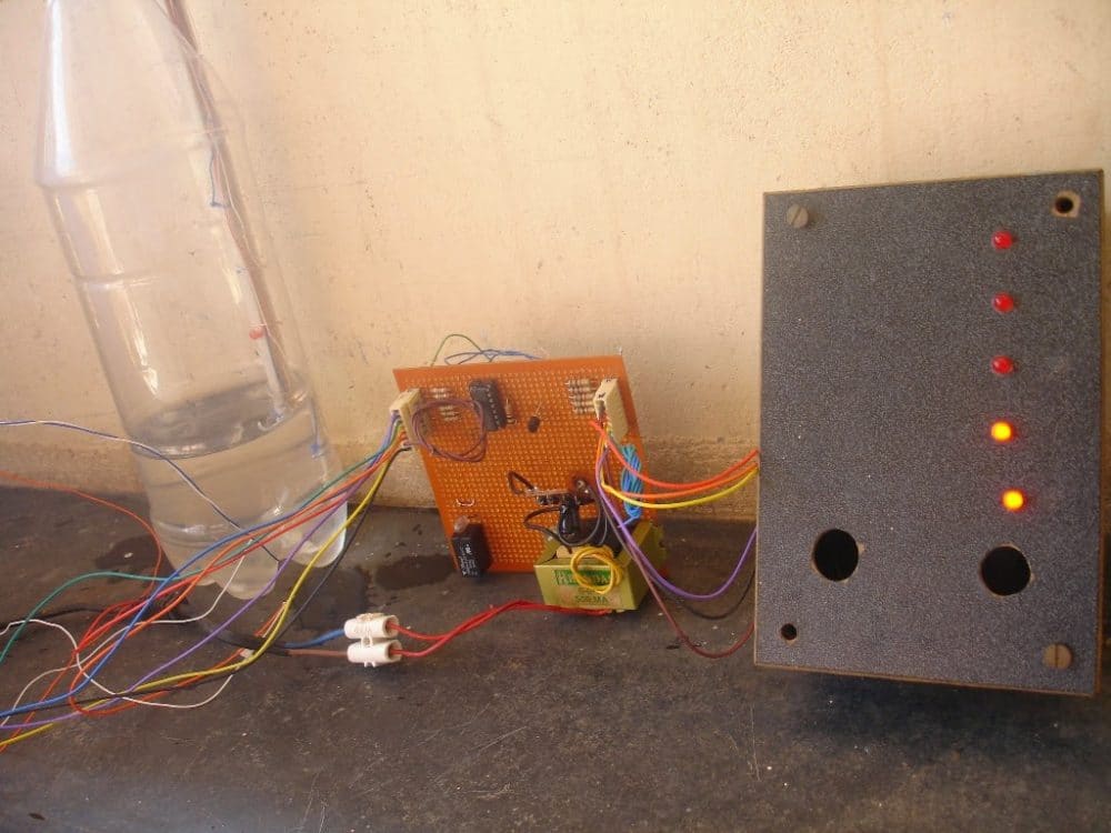
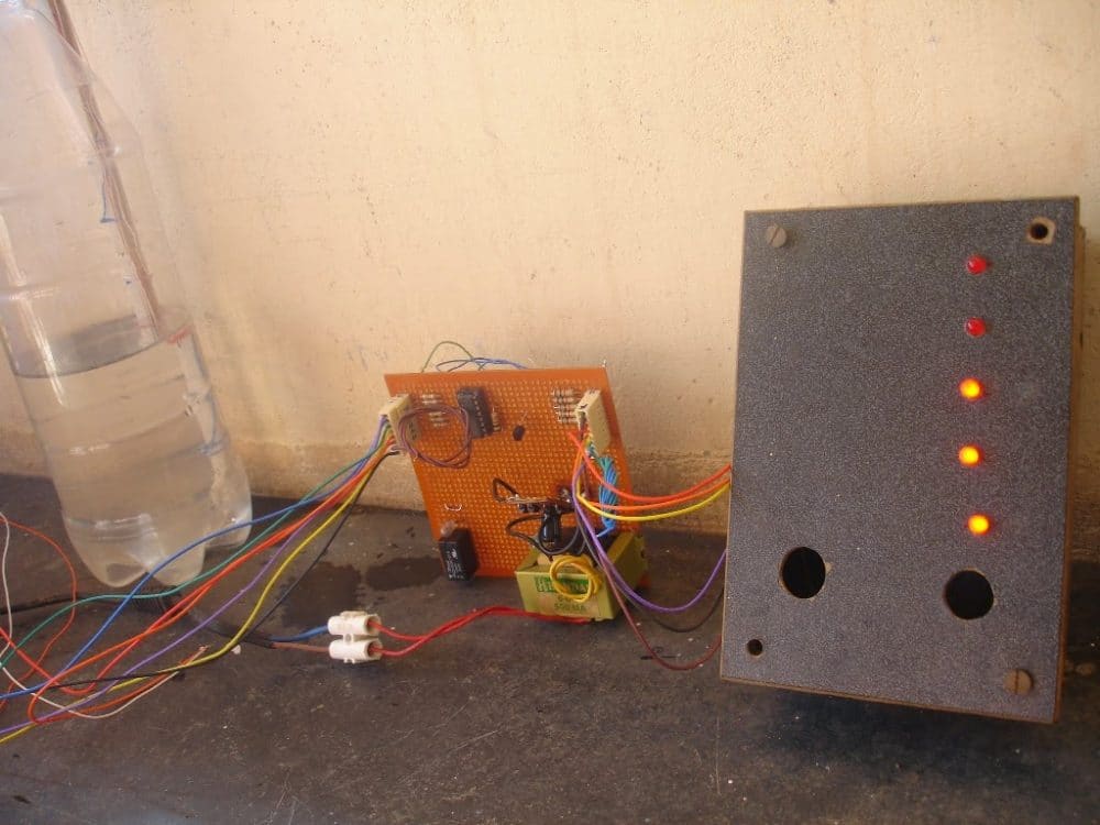
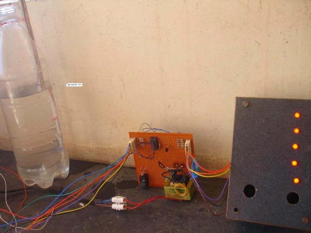
Practical Tested Prototype
The above circuit was successfully built and tested by Mr. E.Rama Murthy who is one of the regular and dedicated readers of this blog. The following pictures of the built prototype were sent by him, let's investigate the results closely.


Comments
and what about during ligtning period, since it is connectd to mains through transformer, if it affects than suggest me the rating of fuse to connect to the primary of transformr
Sir where to connect the MOV at 220v ac side or 6v ac side
use an 300V MOV at the primary supply input for safeguarding the circuit from a possible distant lightning induction.
sir if i connect 12 ac in place of dc in the above, then will circuit work? If yes than will the tank water give any shok?
And i have one more question that i have made the same thing but the circuit is different in which 6V ac is used by a stepdown 220/6 v 500mAmp transformer. And the circuit is working quite good, so my Question is that is their any chances of shok in tank water if any person come in contact.
hussain, ac supply will damage the IC immediately, not sure how it's working for you.
you can put a diode in series with the positive for applying a pulsating DC, that might work but never use AC.
6V, or 12V pulsating DC or AC will not give any shock in the water.
and also sugest such materials as probe which will not get corroded very soon, amd also which wire should i use cu or aluminium
use tinned copper….apply thick coat of good quality solder on copper.
sir, i have made this project.. And it was working quite good but after two week the probe get corroded and due to this circuit is not working properly ie led light flactuation . Etc
Hussain, you can try using pure stainless-steel probes and see if that helps.
Hi, It is IC CD4049UB a good alternative to IC 4049 ?
it' one and the same
Im not an electronic guy. Is there any way you can do in and sell it to me?
sir i want connect an alarm so what modifications should i do if the alarm is high power alarm generally used as door alarm
thanx
sir your posted image has been included with detail. was it correct sir this would be more usefull to new commers
https://lh3.googleusercontent.com/-AJkM6aVBKnY/VTyUB774UvE/AAAAAAAAA_8/WnNsvn_jwUE/w163-h110-p/20150426
Hi Manjunath, you can use 4 gates out of the six, but make sure that the input pins of the remaining two unused gates are connected either to ground or to the positive rail…the outputs can be left open.
you can arrange the gates as you want, all the gates are exactly similar and can be positioned randomly or as desired, a specific sequence is not necessary.
Sir , In this circuit can I make only 4 indicator levels instead of 6 as shown in diagram.
was it works,
If it works, wheather should I connect input gate and output gates one by one order or any
gates like for level 1 input pin 3 of 4049 and output pin 2
For level 2 input pin 9 output pin 10
visa versa
manjunath, sorry I could not properly understand what you are trying to say….
yes, the explanation in the above article is correct and is in detail
your image is too small to see.
I have added the IC image just to make it clear about the inputs and the outputs and the supply pins to the newcomers.
Hey, i'm in software domain. Actually i need this circuit design to implement in my home.
Could you please send me detailed labeled circuit diagram with IC 4049 connected.
Thanks in advance..
Keep up the good work.
yes that's absolutely correct
The "triangles" inside the 4049 and the corresponding pinouts are shown in the second pic, you just have to connect the involved pins as per the circuit diagram given in the first pic, it's quite simple actually.,
any "triangle" can be positioned anywhere all are identical with their characteristic
hello my name is amir'm from Buenos Aires Argentina.
I need your help designing a circuit.
I need a circuit to heat water in a tank and when it reaches a temperature has to cut the feeding 220vca..y … also it disconnects itself from already thank you very much.
Hello, I'll try to design it and let you know once it's completed.
how much output current on any pin of 4049. because i want to connect alarm bell with pin. so i want to know how much power of bell i can use.
and i want to use door bell like (ding dong) with this circuit then how can do this. i think i require one another circuit in which thyristor is used to connect with this circuit for connecting ac bell. Am i right?
10mA will be available at the gate outputs.
It's advisable to use a transistor/relay driver at the output of the gate for operating a high power bell, whether AC or DC
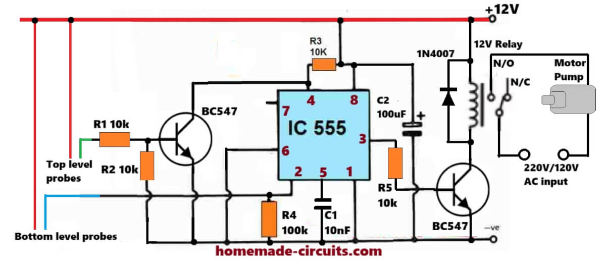
yes the diagram looks OK to me, the latching would work and stop the relay from reactivating, but the circuit will need to be reset each time the water level goes below the lower threshold.
the shown 2M2 is also a big value, but if you want to use even bigger values you can try, for example 10M could be tried instead of 2M2.
Hi,
Yap it should be switched off manualy after filling.
I have one question it seems that logic gates have big resistance so I think about putting resistor of bigger value in parallel with logic gate so that final resistance is lower and then it could work in water with big resistance, is it possible in real world? It seems that it is working in simulation but I am not sure.
Hello Thanks!
Yes, that looks OK to me. but the relay will keep switching everytime the water level dips below the upper threshold.
Hello,
this is a bit tweaked circuit and it seems in simulation that it could be used to turn water pump off automaticly when water reaches some level…but I have no idea how it would act in real life xD
s21.postimg.org/bkntb9dpj/auto_off_water_pump_circuit.png
Best regards.
Hello Swagatam,
What would be the effect, if base of the transistor is connected at the same position of the LED of gate 6 which will energize a relay to open its normally open contact?.
If it can not work that way, what needs to be done to consider it and automatic control circuit?.
Regards
Hello Kevin,
Yes it can be wired in that way, the idea has been discussed in the following article:
https://www.homemade-circuits.com/2012/01/circuit-provided-in-this-article.html
hello sir
could u pls suggest a circuit for alarm which use input from one of the output of above circuit
coz i have three overhead tank n a underground tank . want to use single speaker (8 ohm )
yes any audio circuit as per preference can be tried
thank you
i will keep looking for it . can we use other sound library ic available in the market like IC HT2844P or pic16f887
as soon as I'm free I'll try to present it in the above article.
THANKS
but could u pls refer me its circuit diagram
hello aashish, do the following things:
make a 555 astable multivbrator circuit with a frequency that would generate the required alarm audio
connect pin1 of the IC to a 8050 transistors collector, connect its emitter to ground, base to 4049 ICs any one of the outputs via a 1k resistor.
connect the speakers one of the wires together and connect the common joint to pin3 of the 555, similarly connect the common wire joint of the speakers to ground.
that's it once activated all the speakers would start buzzing
thank you
dear ashish,
yes the remaining pins are not used.
a piezo buzzer can be connect directly across one of the outputs of the gates and ground, just as the LEDs are connected.
dear swagatam,
refering to pin out diagram only 2,3,4,5,6,7,9,10,11,12,14,15, numbered pins are to be used and others left idle.
also pls suggest to how to add buzzer to the circuit
Please say that anyone who tested this experiment. Is all perfect circuit. for usage
I think at 12V electrolysis could be very negligible to affect much especially without any acidic agent in water, moreover natural electrolysis of this kind will only dissociate water ions not the electrode ions.
Lead may be tightly bonded in solder metal so it will not easily separate, and whatever may dissolve could be again too insignificant to cause any health issues.
yet for extreme safety two things can be done, use electroplated electrodes (tin or chromium plated) and connected 100k resistors in series with each sensing terminals for reducing current such that only the IC is able to sense it without initializing electrolysis.
with AC the circuit will not operate and moreover higher volt could force more electrolysis to occur.
You can tin the terminals with a thick layer of solder for reducing corrosion as tin is resistant to most passive chemical reactions.
The indicated ground is the 12V adapter supply ground (negative), it's not the earthing type of ground, so lightning will not get attracted to it in anyway.
You can connect and ground the tank body with the your home earthing wire for more safety if you feel it necessary.
Hi
One basic question.
What is the current being passed through the probes?
Is there any risk to human life when the current passes through water?
I dont want to have shock when I turn on tap in my kitchen.
Pallavi
Hi,
It would be 100 times less than your cell phone battery, so it's absolutely safe.
Refer to the IC pin out diagram given below the circuit diagram, you can easily compare and replace the pin numbers over the circuit and understand the inputs and the outputs appropriately.
refer to the diagram and count them, it's so simple.