No complex wiring, no costly MOSFETS and no cumbersome heatsinks, yet a powerful 200+200 watt stereo amplifier circuit, which can be built within hours using just a couple ICs, right in your home.
Yes we are discussing the state-of-the-art thick film hybrid IC STK4050II, by SANYO.The IC is specifically designed for amplifying music at an astounding rate of 200 watt power.
Introduction
The involvement of minimal number of components especially makes this device perfectly suitable for the many hobbyists who aspire not only making a powerful amplifier at home but also for enjoying its application.
The IC is able to effectively drive sub-woofers and therefore also becomes ideally suitable as a car stereo amplifier.
The salient features of the IC STK4050II includes the following:
- Compact streamlined package resulting a sleek looking amplifier design.
- Simple heatsinking clamping facility with large surface area, for better heat dispersal, resulting in an enhanced output capability.
- The internal circuitry of the IC entertains a constant current operation which helps reduce switch-ON and switch-OFF "thump" noise in the speaker.
Maximum Operating Parameters of the IC
- Huge maximum power supply rating at +/- 95 volts resulting powerful outputs at lower currents.
- Typical operating voltage may be around +/- 66 volts.
- Speakers used at the output of the circuit should be ideally a 8 Ohm type.
Operating Characteristics are:
- Quiescent current is internally set at 100mA for voltages upto Vcc +/-80 volts.
- Output power with the above conditions will be around 200 watts.
- Total harmonic distortion will not exceed 0.4% at frequencies between 20Hz and 20kHz.
- Frequency response of the IC is also very high, between 20Hz and 50kHz.
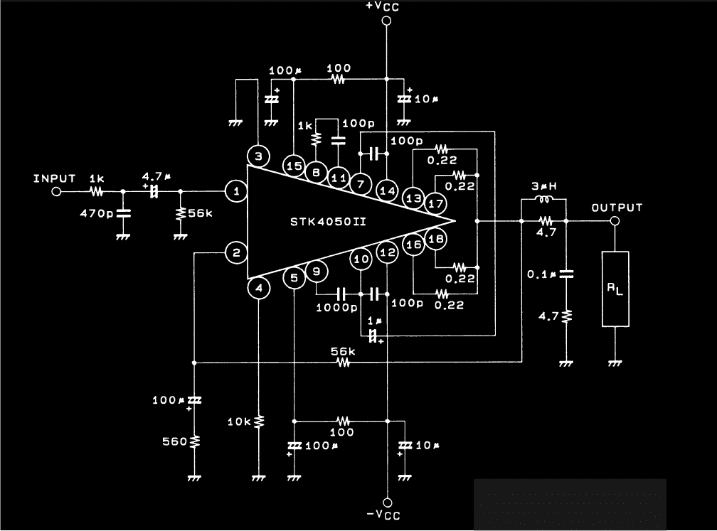
- The circuit diagram below shows a neat little amplifier circuit, two of them may be built for obtaining stereo outputs.
- The configuration is very simple, mostly all the complexities are solely handled by the chip itself.
- The input consists of a regular low pass filter components for rejecting high frequency interferences.
- Other features like automatic gain control, offset control and stability control, everything is effectively tackled by the shown design.

Questions & Answers
Good Day Sir, just want to ask for your help Sir, just want to make a freshwater fish stunner powered from a 12v battery, im done searching online but no luck.
I want a circuit that make the supply battery to last longer, safe to human but powerful on freshwater fish. btw we're going to use it in our backyard fish pond. Thank you Sir.
Good day Marife, anything that would stun the fishes would stun a human being also, because to stun a fish a high voltage pulse would be required which could cause some sting to a nearby human also in water.
Hi Sir, regarding the power supply, do you have the circuit for it? what i have with me is only the trafo ( 220v P , 25-0-25v S ) what is the value of diodes (rectifier) and capacitor (smoothing, filtering )? regulated or unreg? thank you.
Hi Marife, you can build it as per the following diagram:
2.bp.blogspot.com/-9NDWuKl4c7o/TwhC3aw2KgI/AAAAAAAAAp4/HqBS5VDHcLI/s400/powe+supply.jpg
sir i am not intented to drive the 400 W sprakers using home theater…. the only thind i want to do is to make the home theater woofer functioning parallel to the 40 to 400 W speakers using the same channel of the STEREO CONTROL UNIT…
So i want to know that whether any problems will occur to the STEREO CONTROL UNIT ( which is capable of driving the original 400 W speakers ) on doing so ???
Hi Marife, don't remove anything from the shown design, if you want to add the low pass filter add it without disturbing the shown set up, it will still work perfectly.
Hi Sir, i will try to make it myself, i have another question Sir, can i remove all components connected to pin# 1 of the IC and replace it with a much better powered low pass filter? because i already had a working circuit of a low pass filter from my previous project with a power input of +-15 vdc? if yes should i connect common ground of the two circuit?
Thank you for helping people you don't even know Sir, God bless!
Hi Marife, a 5 watt will be good.
Hi Sir, what exact wattage of resistor should i use? what i have in my box was a 4.7 ohm 2 watt peanut shape , a 5 watt and a 7 watt wirewound rectangular in shape. thank you.
Marife, you can make it by winding 20 turns of a super enameled copper wire, it should not be too thin, it could be around twice as thick as our hair.
wind it directly over the 4.7 ohm high watt resistor
Sir i can't find a 3uh coil, can i salvage it from old circuit board or can i make it myself?
If your car amplifier is rated for handling 400 watts max, further increase in the speaker wattage will only make it warmer…not recommended.
yup sir…..but Home theater speakers are not necessary…. i need only the 400 W speakers
thank you sir
Arun, you mean you want to drive the 400 watt speakers from the car amplifier and use the same signal for driving the home theater and its speakers, right? nothing will go wrong with this set up, you may do it.
sir, the stereo unit in my car outputs a total of 4 channels of which only one is working.. i have used that channel for giving input to the home theater as i said before… now i want to make a little modification in the current design…. I am going to remove the speakers which are already connected to the home theater and to use the original CAR STEREO speakers instead of them… The home theater speakers are rated at 18 W each whereas the CAR STEREO speakers 40 to 400 W each….. So the150 W CAR INVERTER used will not be suitable for driving these Car speakers instead of home theater speakers…. So i need to operate these speakers parallel to the Home theater woofer for better efficiency, and sound clarity……
So what is you remark in connecting the Home theater inputs from the working channel of the CAR STEREO CONTROL UNIT along with the Original Car speakers using the same channel ????
If your home theater amplifier is capable of driving 400watt speakers then may be you can use it for the purpose, otherwise your home theater devices could become hot and stop working
Sir,
I got a simple idea for making that timer( which i had discussed in my previous email ) into an intelligent timer as i said…
The idea is :
Just give a Positive signal to the diode D1 when power supply fails and keep the whole set up working under a battery voltage….At that time the CD4060 IC will stop oscillating giving high output…. So the IC will get paused….
Also remove the given positive signal when Power supply returns thereby leaving the IC from the paused state and it will continue to oscillate from the paused point and all the set up will be powered by Actual power supply….
-ve logic at the output side should be used to activate the relay during set time…
Plz put your remarks on this IDEA sir ?
Can it be made practical ?
Is there any problem in forcing an external signal to D1 ?
….you could probably try your idea also, I think it could work, as it would stop the osculations from reaching the ICs internal circuitry.
Arun, I am not sure if that would work because the capacitor would get discharged in the course, the idea is to prevent C3 from discharging…..I have already published the article a few days back, I forgot to inform you regarding it, here's the link for your reference:
https://www.homemade-circuits.com/2014/07/timer-circuit-with-auto-pause-and.html
Ok sir… Now i got it…. In my CAR INVERTER ( which is a 150 W cigarette type inverter that can be plugged into a cigarette type jack normally placed inside a car ) when i am checking the output voltage using a multimeter it shows a correct reading of 240 V… But when the output terminals are checked using a TESTER, the TESTER LED brights up even at Neutral Terminal….. But the Home theater is working perfectly under this condition…..
What is the cause for this behaviour of the TESTER ???
Will it be harmfull for any Instruments in connecting at the output of this inverter permanently ??
Arun, inverters don't have a neutral, their outputs work in a push pull manner, meaning both the terminals become phase and neutral alternately 50 times per second, that's the reason your tester illuminates on both the terminals of the inverter output.
Sir i have set up the home theater inside my car successfully.
But a simple problem persisted at that time..
That problem is ::
A nuisance high frequency sound heard from the home theater speakers when input for the home theater ssystem is kept open… I have sent a mail to you describing the problem i have faced. Plz check it out soon sir….
Arun, It will obviously happen because the wires are acting like antennas picking up the atmospheric RFs and disturbances, you must use shielded wires or put high value capacitors across the input of the hometheater and ground.
Sir, what about the email related to a timer circuit. that i have recently send to your hitman inbox ??
Arun, I answered your emails with a no solution to the problem, however now I think that may be it's possible by cutting off the capacitor link from the circuit as soon as the mains fails and vice versa.
If possible I'll try to post the design through a new article.
Sir Let me clarify onething regarding the wiring of a 150 W Car inverter….
I know for driving the 150 W load, the input side of the inverter transformer should have to handle a max. current of 12.5 A…
so my doubt is whether i can use an electric cable whose specification is 1.0 sq mm and can handle a maximum AC voltage of 1100 V ??
1mm could be risky, use 2mm diameter wires
Ok. that means the connections i have made for inputting the signals to the home theater ( making the signals with respect to the ground or -ve of the battery ) seems to be correct ??
Then why didn't get input signals from other wires except the two which have been used ?
On measuring with the multimeter every single output from the CONTROL unit shows 5.2 V…means signal is present…( i have also checked this by connecting the actual speakers in the CAR ) but among which only two can give the Home theater better input signals…..
I can't suggest until I check it myself,
there are many ways actually, you can use a pair of headphones and check each of the wires with reference to ground, if a few of the wires don't respond check those with reference to other points in the amplifier power supply sections, you can also use LEDs for the same..
I have an another doubt also..:
Is it dangerous for the Home theater ( 86 W ) to be powered by an Ordinary 100 W Square wave inverter ?
Or in other words, Should i have to use a pure sine wave one ??
square wave is safe as long as it generates 220V RMS, but will generate a humming noise in the speakers
Finally i got it Sir…
For safety, i have added a 10 K resistance and a 1 uf / 400 V POP capacitor in series with each signal before feeding them to the home theater inputs by RCA cables.. I got the two speakers working properly and also the BASS as well ass TREBLE improved much compared to the previous case since there exists control for them at both ends ie., at CAR STEREO CONTROL UNIT side and HOME THEATER SYSTEM side….
One thing i have noted is that, a pair of cables that were initially driving each speakers in the original CAAR STEREO BOX carries similar signals and no ground signals exists there..
The Stereo Amplifier Outputs are 4 in no.s intented to drive 4 speaker units ( FRONT RIGHT, FRONT LEFT, REAR RIGHT and REAR LEFT )… Only two distinct wires from that group could drive my HOME THEATER system in a correct way.. I think that wires are :
One from the Signals going to REAR RIGHT and the
Other one from the Signal going to FRONT LEFT…
A ground signal common to both these signals was taken from the battery -ve terminal.
So could you please comment on these connections and give your valuable suggestions here Sir……
One doubt : HOW CAN A SPEAKER ( which was originally in the car ) BE DRIVED USING THE PAIR OF SIGNALS COMING TO IT IF THOSE WERE CARRYING SAME SIGNALS ???
OK that's great!
In the previous comment I already stated that the outputs could be differential type, meaning those are not ground referenced or single ended types rather are push-pul types.
the signal content on each pair of wires are similar but are constantly changing polarity in a push-pull fashion casing the speaker coils to respond in the same manner.
I got your email sir. thank you
I am a little bit scared of connecting the wires carrying amplified sound signals ( which were actually driving the original speaker set in the car ) directly as input to the home stereo as i described in my email…. Also i found that set of wires going to each wires are separate pairs and no common lead exists….. So Can i use a pot to reduce the signal levels compatible with the home stereo system ? If it can ;
1). How can i connect the pot before a signal input ? Is that between the pair of wires of a signal input ?
2). How can i measure the audio signal level ? By measuring voltage ? Does that amplified signal coming from the Car Stereo Controller unit has high value of voltage compared to a non-amplified signal ?
Hi Arun, thanks!
If the wires are two different pairs, it indicates a differential type of output from the amplifier, these are not the usual single ended types, however I think you can use any one wire from each pair as the input for your home theater.
Pots are already installed in your home theater, so putting another at the output won't make sense and moreover it won't help the cause….instead you can try using 1uF/400V PPC capacitor in series with each of the input wires. The capacitor will restrict anything that may be dangerous for the home theater, although the home theater already has such protection capacitors buit-in.
Sir It z me Arun…
I am in the middle of doing a new efficient circuit…
In my car, two sets of quality speakers ( PIONEER ) have already been placed, but the system can't produce enough bass also clearness..
So i have bought a new home theatre system ( IMPEX ) in the intention of altering it for use instead of the CAR speakers…
The system readily is working directly under AC…. SO the things that i have to done are listed ;
(1).
The system should work under 12 V car battery…
Home theater ( 2.1 ) system has a power rating of 50W( woofer ) + 18*2( speakers )….total of 86 W only…
So a simple circuit is necessary to operate the system under car battery voltage… Since the system is bought new, i am not interested in altering its internal circuit since it affects the granted warranty…..
(2).
So if the solution for the above problem is a 100 W inverter , any square wave inverter do that purpose , or should i have to opt a pure sine wave inverter considering the health of the Home theater system ?
(3).
As already said i have a stereo set already in Car… So i want to replace it completely with the new system. But the confusion is how to use the wires that is leading to the speakers in the Present Stereo Set with the new home theater system… The Home theater system has two input jacks ( for stereo input ) on it to plug only RCA cables…. So i think i can use the wires that is going to each speakers in the current stereo system ( total of 4 wires of which 1 is thought to be common ) to incorporate with two RCA cables from the Home theater inputs…
I have sent a mail showing all the necessary pictures for assisting you to solve all these issues..
Hope you will help me as before in a very good manner.
Thank you …
Arun Dev
Thanks Arun, I'll reply you soon with a suitable solution, let me go through the request properly….
HI,
Plz may i get info about parallellinf stk amp's o/p channels???Because i've stk4231 which's 100+100 @8ohms.Can i parallel them to use for 200W @ 4ohms???
The inputs can be made into common for sharing a single input, however the outputs would need to be connected with two separate speakers for better performance and for the required increased power output..
Hi engineer,
Do you have a 100 watts rms car stereo diagram with 12 volts power supply?
2nd one, do you have a computation on how to build 220v (primary) and 15v-0-15v (secondary) power transformer? What is the size of the ferrite core to be used?
Thanks,
Edmon
Hi Edmon,
You can try the following design, but you mayrequire to elevate the 12V to much higher level using a converter for this design:
https://www.homemade-circuits.com/2012/04/how-to-make-simplest-100-watt-mosfet.html
sorry, I do not have any info regarding the trafo that you have suggested
Dear Gerart,
Do you mean an audio mixer circuit?