In this post we will comprehensively discuss how to build a 500 watt inverter circuit with an integrated automatic battery charger stage.
Further in the article we will also learn how to upgrade the system for higher loads and how to enhance ot into a pure sine wave version.
This 500 watt power inverter will convert a 12 V DC or 24 V DC from a lead acid battery to 220 V or 120 V AC, which can be used for powering all types of loads, right from CFL lights, LED bulbs, fans, heaters, motors, pumps, mixers, computer, and so on.
Basic Design
An inverter can be designed in many different ways, simply by replacing the oscillator stage with another type of oscillator stage, as per user preference.
The oscillator stage is basically an astable multivibrator which could be using ICs or transistors.
Although an astable based oscillator can be designed in various ways, we will use the IC 4047 option here since it is a versatile, accurate and a specialized astable chip designed specifically for applications like inverers.
Using IC 4047
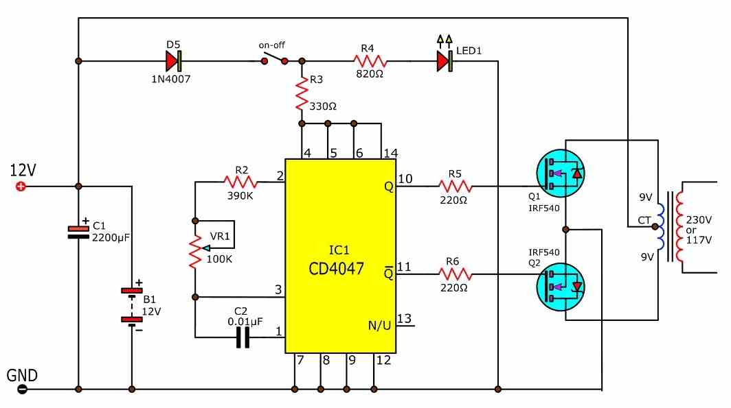
Making any inverter using the IC 4047 is probably the most recommended option due to high accuracy and readability of the IC. The device is a versatile oscillator IC which provides a dual push pull or flip flop output across its pin10 and pin11, and also a single square wave output at pin13.
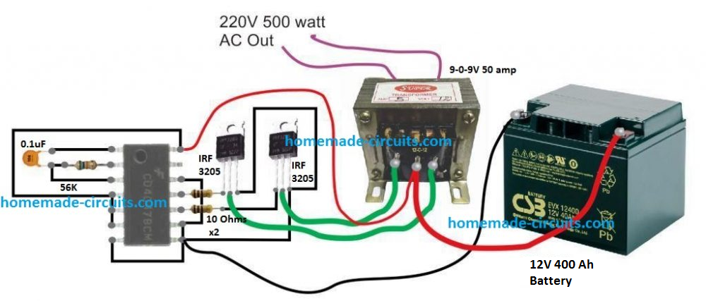
A basic 500 watt inverter with a square wave output can be as simple as above to build. However, to upgrade it with a battery charger we may have to employ a charger transformer rated appropriately as per the battery specifications.
Before learning the charger configuration let's first get acquainted with the battery specification required for this project.
From one of our previous post we know that the more appropriate charging and discharging rate of a lead acid battery should be at 0.1C rate or at a supply current that's 10 time less than the battery Ah rating. This implies that to get a minimum of 7 hours back up at 500 watt load, the battery Ah could be calculated in the following manner
Operational current required for a 500 watt load from a 12V battery will be 500 / 12 = 41 Amps approximately
This 41 amps needs to last for 7 hours, implies that the battery Ah must be = 41 x 7 = 287 Ah. However, in real life this will will need to be at least 350 Ah.
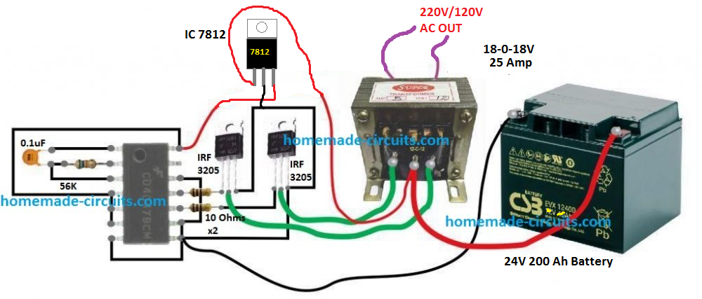
For a 24 V battery this may come down to 50% less at 200 Ah. This is exactly why a higher operational voltage is always advised as the wattage rating of the inverter gets on the higher side.
Using 24 V Battery
In order to keep the battery and the transformer size smaller and cables thinner, you may want to use a 24 V battery for operainf the proposed 500 watt design.
The basic design would remain as is, except a 7812 IC added to the IC 4047 circuit, as shown below:
Schematic Diagram
Battery Charger
To keep the design simple yet effective, I have avoided the use an automatic cut off for the battery charger here, and have also ensured a single common transformer is used for the inverter and the charger operations.
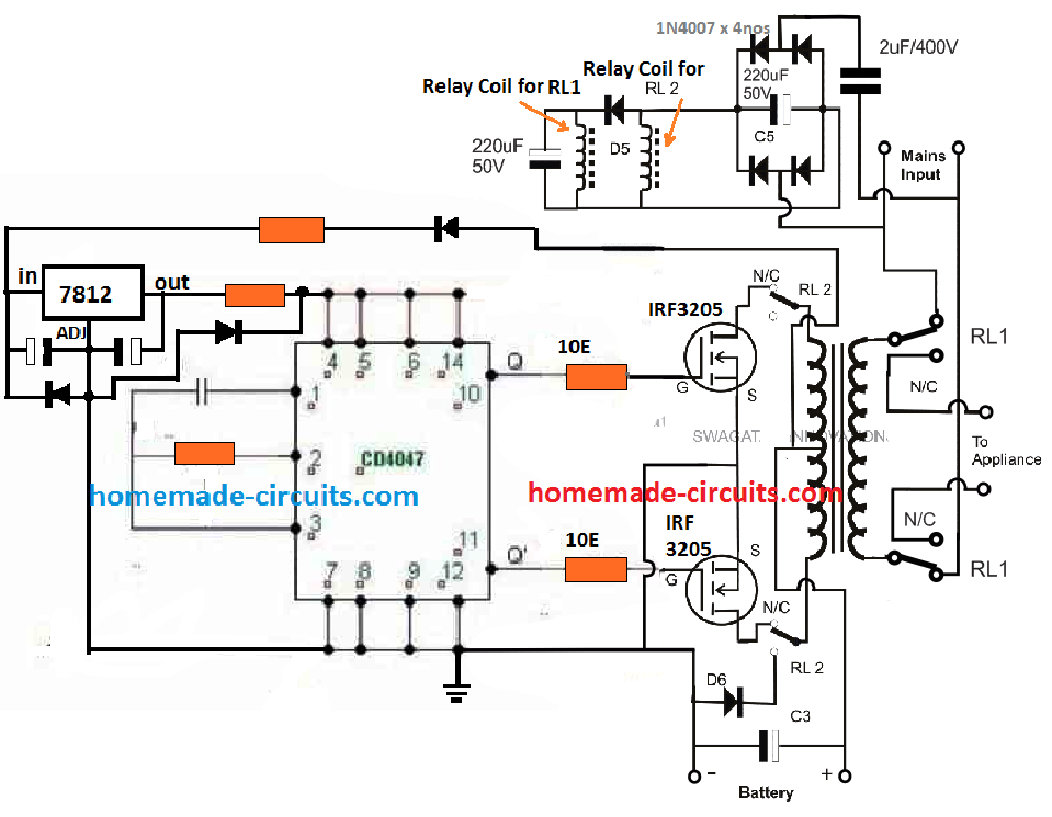
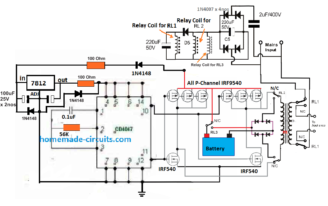
The complete circuit diagram for the proposed 500 watt inverter with battery charger can be seen below:
The same concept has been already elaborately discussed in one of the other related posts, which you can refer to for additional information.
Basically, the inverter uses the same transformer for charging the battery and for converting the battery power to 220 V AC output. The operation is implemented through a relay changeover network, that alternately changes the transformer winding to charging mode and inverter mode.
How it Works
When grid mains AC is not available, the relay contacts are positioned at their respective N/C points (normally closed). This connects the drains of the MOSFETs with the transformer primary, and the appliances or the load connect with the secondary of the transformer.
The unit gets into inverter mode and begins generating the required 220V AC or 120 V AC from the battery.
The relay coils are powered from a simple crude transformerless (capacitive) power supply circuit using a 2uF / 400V dropping capacitor.
The supply is not required to be stabilized or well regulated because the load is in the form of the relay coils which are quite heavy duty and will easily withstand the switch ON surge from the 2uF capacitor.
The coil for RL1 relay which controls the mains AC side of the transformer can be seen connected before a blocking diode, while the coil of RL2 which controls the MOSFET side is positioned after the diode and in parallel to a large capacitor.
This is intentionally done to create a small delay effect for RL2, or to ensure RL1 switches ON and OFF prior to RL2. This is for safety concerns, and to ensure that the MOSFETs are never subjected to the reverse charging supply whenever the relay moves from inverter mode to charging mode.
Safety Suggestions
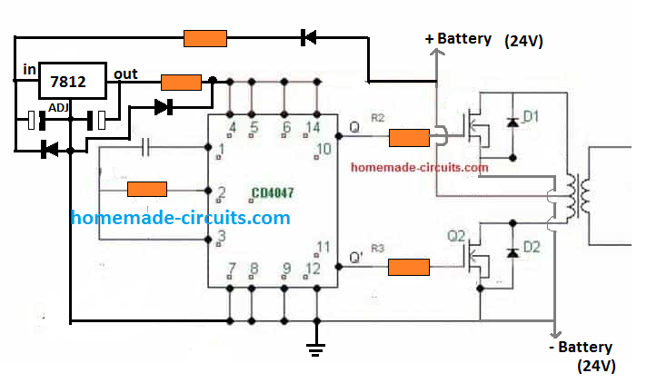
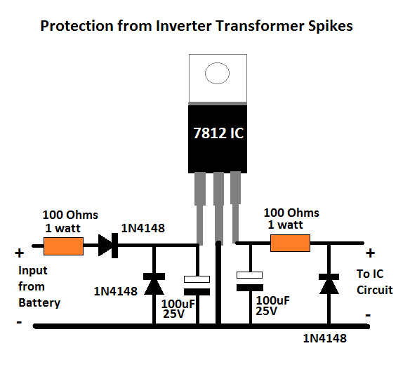
As we know, in any inverter circuit the transformer works like an heavy inductive load. When such a heavy inductive load is switched with a frequency, it's bound to generate a massive amount current spikes which may be potentially dangerous for the sensitive electronics and the involved ICs.
To ensure proper safety to the electronic stage, it may be important to modify the 7812 section in the following manner:
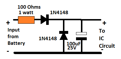
For a 12V application, you can reduce the above spike protection circuit to the following version:
Battery, MOSFET and Transformer Determine the Wattage
We have discussed this many times through different posts that it is the transformer, the battery, and the MOSFET ratings that actually decide how much power an inverter can produce.
We have already talked about the battery calculations in the previous paragraphs, now let's see how the transformer can be calculated for complementing the required power output.
It is actually very simple. Since the voltage is supposed to be 24 V, and power 500 watts, dividing 500 with 24 gives 20.83 amps. Meaning the transformer amp rating must be above 21 amps, preferably up to 25 amps.
However, since we are using the same transformer for both charging and inverter modes, we have to select the voltage in such a way that it suits both the operations optimally.
A 20-0-20 V for the primary side appears to be a good compromise, in fact it is the ideally suited rating for the overall working of the inverter across both the modes.
Since, only one half winding is used for charging the battery, the 20 V RMS rating of the transformer can be used for getting a 20 x 1.41 = 28.2 V peak Dc across the battery with the help of the associated filter capacitor connected across the battery terminals. This voltage will charge the battery at good rate and at the correct speed.
In the inverter mode, when the battery is at around 26 V, will allow the inverter output to be at 24/26 = 220 / Out
Out = 238 V
This looks a healthy output while th battery is optimally charged, and even when the battery drops to 23 V, the output can be expected to sustain a healthy 210V
Calculating MOSFET: MOSFETs basically work like switches that must not burn while switching rated amount of current, and also must not heat up due to increased resistance to switching currents.
To satisfy the above aspects, we have to make sure that the current handling capacity or the ID spec of the MOSFET is well over 25 amps for our 500 watt inverter. Also to prevent high dissipation and inefficient switching the MOSFET's RDSon spec must be as low as possible.
The device shown in the diagram is IRF3205, which has an ID of 110 amp and RDSon of 8 milliohms (0.008 Ohms), which actually looks quite impressive and perfectly suitable for this inverter project.
Parts List
To make the above 500 watt inverter with battery charger, you will need the following bill of materials:
- IC 4047 = 1
- Resistors
- 56K = 1
- 10 ohms = 2
- Capacitor 0.1uF = 1
- Capacitor 4700uF / 50 V = 1 (across the battery terminals)
- MOSFETs IRF3205 = 2
- Diode 20 amp = 1
- Heatsink for the MOSFETs = Large Finned Type
- Blocking Diode Across MOSFETs Drain/Source = 1N5402 (Please connect them across drain/source of each MOSFET for added protection against reverse EMF from the transformer primary. Cathode will go to the drain pin.
- Relay DPDT 40 amp = 2 nos
Upgrading to Modified Sinewave Inverter
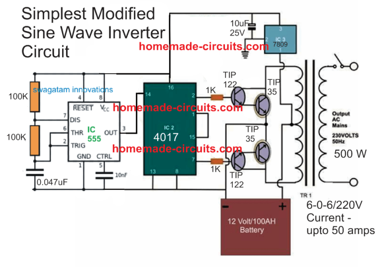
The square wave version discussed above can be effectively converted into a modified sinewave 500 watt inverter circuit with much improved output waveform.
For this we use the age old IC 555 and IC 741 combination for manufacturing the intended sine waveform.
The complete circuit with battery charger is given below:
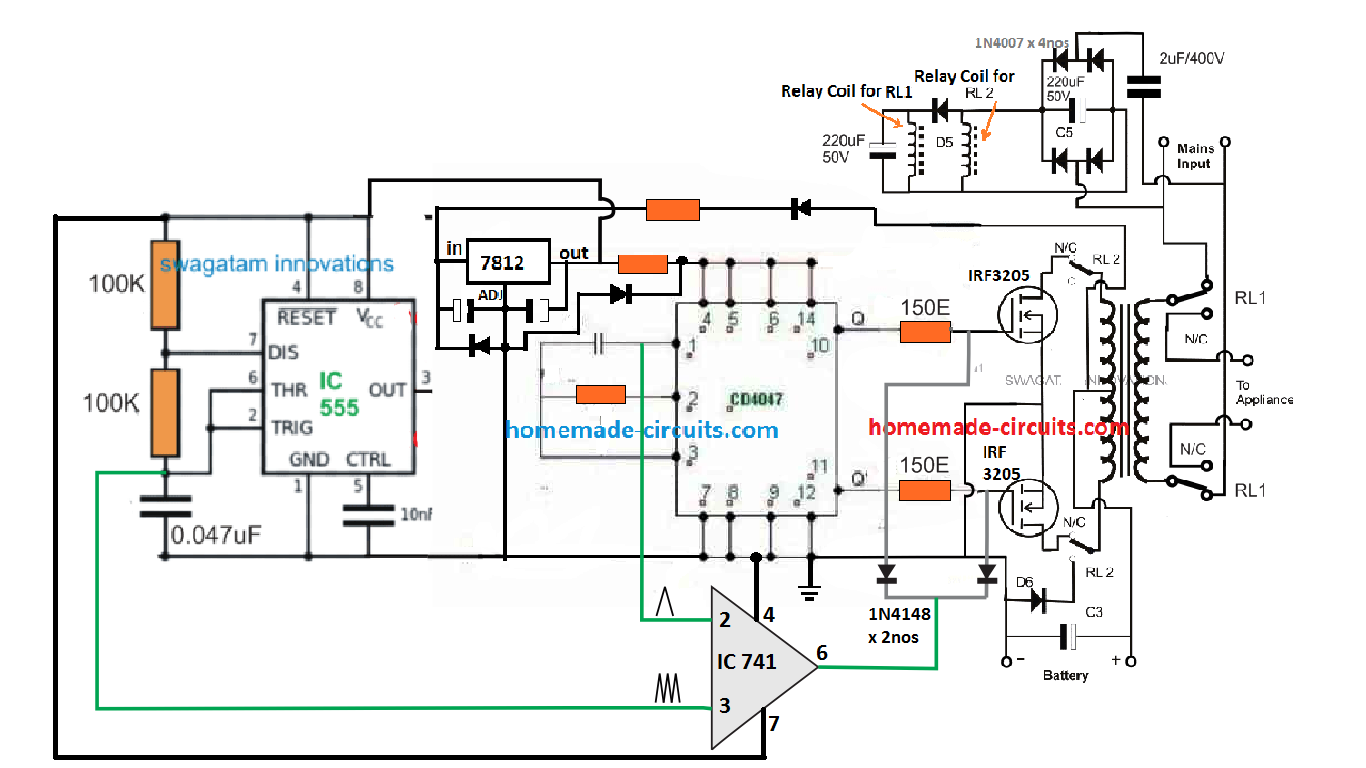
The idea is the same which has been applied in a few of the other sinewave inverter designs in this website. It is to chop the gate of the power MOSFETs with calculated SPWM so that a replicated high current SPWM is oscillated across the push pull winding of the transformer primary.
The IC 741 is used as a comparator which compares two triangle waves across its two inputs. The slow base triangle wave is acquired from the IC 4047 Ct pin, while the fast triangle wave is derived from an external IC 555 astable stage. The result is a calculated SPWM at pin6 of the IC 741. This SPWM is chopped at the gates of the power MOSFETs which is switching by the transformer at the same SPWM frequency.
This results in the secondary side with a pure sinewave output (after some filtration).
Full Bridge Design
The full bridge version for the above concept ca be built using the below given configuration:
For sake simplicity, an automatic battery cut off is not included, so it is recommend to switched OFF the supply as soon as the battery voltage reaches the full charge level. Or alternatively you may add an appropriately filament bulb in series with the charging positive line of the battery, to ensure a safe charging for the battery.
If you have questions or doubts regarding the above concept, the comment box below is all yours.


Questions & Answers
hi, Swagatam, an an electronics technician in Kenya. I need a circuit diagram of an audio amplifier, 100 Watts, using 2SA 1302 transistors. I have plenty of these units.
Hi Johnstone, I do not have any 100 watt circuit using the mentioned transistors. Instead you can try other configurations, as given below:
https://www.homemade-circuits.com/?s=100+watt+amplifier
Hello sir, I build another 24v inverter using a round transformer 500w rated 20v-0-20v. I hv two 200ah batteries in series. The circuit I built is using 14 MOSFETs meaning 7 each side. The challenge am seeing is that it drains the battery faster without load than when with the load. This is contrary to the first inverter I built using two 100ah in series when I was using 10 MOSFETs 5pcs each side. I now have 200ah batteries and that round transformer(500w) so what could be the problem? Do i increase it to 22-0-22 or I decrease the number of MOSFETs to 10 or what can be adjusted sir?🙏🙏
Hello Morris,
Please connect an ammeter in series with the battery positive and monitor the current consumption with load and without load.
It will help you to assess the real problem…actually without a schematic of the circuit it can be difficult for me to judge the fault.
Now between 20-0-20 and 22-0-22 which one of the two can draw more power from the batteries assuming the two transformers are of the same wattage? Or what is the difference there?
Thanks.
20-0-20V will draw more current than 22-0-22V transformer, simply because the 20V winding has less resistance than the 22V transformer.
hi Swagatam, can help me out with circuit diagram of 500-700watts pure sine HIGH-BRIDGE inverter using SG3525N with battery charging and overload protection. Am a vivid follower of u from Ghana.Thank u
Thank you Idris,
Let me figure it out, if it’s is not already discussed in this blog, I will surely design it for you…
Ok thanks. So 22-0-22 stands the best for inverter and will at least last with the battery compared to 20-0-20??? Secondly, can u refer me to a simple and efficient inverter circuit or oscillator using 4047 or sg3525. I bought two 200ah batteries. We have power failure every time here sir.
Thanks.
It will depend on your battery voltage, the transformer primary voltage must be always slightly lower than the battery voltage, provided the inverter is not a PWM inverter.
You can try this simple 4047 inverter circuit:
Make sure add a 12V zener diode across the IC supply terminals.
Hello my lecturer, happy new year there👋 I have upgraded my backup system from 24v to 48v inverter. Now I have two, one homemade and the other inverter 48v (modified sinewave) from Norway. if you have ever come across this inverter which one do you think is the best best to use. please advise .
Hi Morris, sorry, never heard or tried this inverter from Norway, so it is difficult for me to give my opinions on this…
Ok sir. Do u have a diagram too using sg 3525 with a standby indicator and whn it’s switched on the indicator goes off?( Silent oscillator) please refer 🙏🙏
Thanks.
Hello Morris,
sorry, i am not sure how to implement a standby LED indicator for the SG3525, i will investigate it and if I find it will surely let you know….
Hello, please I need the circuit diagram with the components value written besides each of the components because am confused with the diagram
Which circuit are you referring to?
Thanks sir. But do u have a design of oscillator using sg3525…the perfect one and very silent whn inverter is on? If u hv have that inverter circuit pliz refer.
Thanks
Hi Morris,
You can find the best possible designs in the datasheet of the IC, you can also find good designs in the following article. The IC is nor responsible for the noise, the transformer is responsible…it will generate noise if it is not wound correctly or not clamped tightly with the cabinet.
https://www.homemade-circuits.com/sg3525-pure-sinewave-inverter-circuit/
This type of inverter, can it’s supply voltage be directly from a solar panel?
Yes, any DC to AC inverter can be used with a solar panel.
Hello my teacher, I have a circuit like this of yours 👆above. Now can I use 10 ohms resistors connecting gates of the Mosfets instead of 100 ohms and work perfectly? Or what would be the effect? Can it affect efficiency of the inverter or it’s just ok?
Thanks.
Hello Morris,
The resistor is just to safeguard the MOSFET from abrupt voltage spikes, and is actually optional, since the MOSFETs are mostly not impacted by such spikes across the gates.
Also, these gate resistors must be dimensioned according to the operating frequency of the MOSFEs.
The resistor value must be reduced as the frequency increases.
So, basically, using 10 ohms will be fine in your case. Alternatively, you can also use 100 ohms and connect reverse diodes across the resistors to make the situation 100% safe and efficient.
why are same atx transformers have 13pin and same 8-9 pins ,so whats they out put voltage
Swagatam, interesting circuit. This renewed my interest in Solar Power systems. A couple of questions if you have a moment.
1). Is there any benefit to GPS locking the frequency of the inverter? This plays into question 2.
2). In a solar home situation, where you have more devices, exceeding 500 watts, would it be better to upsize the components for greater power, or go with multiple 500 watt units for various rooms of a house; hence the reason of GPS lock for stability and aid with devices needing +/- 1 hz precision?
3). Finally, what are people doing when they have systems as large as 20,000 watts for a whole home?
Thanks for the article. I have have a new winter project.
Thank you Frederick,
I do not have sufficient information regarding GPS frequency locking in inverters, so I cannot suggest much on this. However, as far the inverter frequency is concerned, if we use a voltage regulator for the main oscillator IC, the frequency will remain constant always without fail.
2) I think it is better to use separate inverters to maintain higher efficiency.
3) For 20,000 watt requremenet, as mentioned above people can either have a single large inverter or divide into many smaller inverters.
Please help me sir I have connected the circuit but the voltage at the output is very low 0.65v. I do not know why. I want to design an inverter of 500watt or 100watt
Okon, please check the frequencies at pin10 and pin12 and pin13 of the IC 4047. They should be around 50 Hz, 50 Hz and 100 Hz. If you are not getting these frequencies then your IC is faulty or not configured correctly.
I will trying this plz help me sir
Try an easier and smaller diagram first
Reference to my previous comment. I want to use the ups with solar panels.
It is OK, the solar panels must be appropriately rated, according to the UPS power.
Hello @ Swagatam. I have this 12v blue gate ups (BG653 elite pro) that I want to use as a normal inverter. Do I need to change or add something to it? It uses four CS150N03 transistors.
If I want to increase the power output, what can I do to achieve that? Thanks
Hello @Breno1, UPS can work like an inverter, so you can use that inverter for your application. If you want to increase the output power, you will have appropriately increase the transformer power rating and the ratings of the MOSFET or the transistors.
Sir is that above circuit with spwm generator a 50hz inverter?? Secondly is it suitable for 70 crt television and 60watt standing fan
John, you will have to adjust the frequency to 50 Hz through the given preset. Yes it can be used for a CRT TV and a table fan.
Sir but you already used 100k and 0.047uf capacitor for getting the 50hz while then should I use preset for getting 50hz
Yes, you can adjust one of these two components (or both) with a frequency meter to get a 50 Hz output.
The shown value may not be exactly accurate, so please confirm with a frequency meter.
I don’t have multi meter for adjusting frequency. Can I use the above value
Without a frequency meter you cannot confirm the frequency so you will need a frequency meter.
Hello sir! I want to ask this 500 watts inverter that if can be upgraded to 1000 watts? I love the design because of it self-charge battery. What should I add for the said upgrade?
Hello Diltone. I would recommend you to first try the 500 watt version. If you are successful then you can upgrade it to 1000 watts by adding more mosfets in parallel, a bigger transformer and a higher rated battery.
Is this pure or modified sine wave?
It is a square wave inverter
Does your 1kva power inverter article is a pure sine wave sir? Can I use it like electric fan and charging a phone?
Yes, the first circuit from the following article is almost a pure sine wave, and any electrical or electronic load will work with it:
Make This 1KVA (1000 watts) Pure Sine Wave Inverter Circuit
With the 1kva power inverter. Can I add the battery charging on the said circuit?
You can add a separate battery charging system. I would recommend a separate transformer based battery charger circuit.
can we use 12 volts output for battery charging instead of 24 volts .and how many volts coil of RL1 to RL3.
Can you please tell me which circuit are you referring to?
Do you have that article?
You can try the 3rd circuit from this article, you may have to upgrade the parts depending on the battery specifications:
https://www.homemade-circuits.com/how-to-make-current-controlled-12-volt/
Thank your for keep replying my queries. I really want to build an power inverter and it happen I discover your site which so helpful. I hope you don’t mind if I keep asking some questions concerning about power inverter. So here’s it my other query.hehehe.. can I use car battery or a battery that is specifically for power inverter?
No problem, you can ask your questions, I will try to answer them as much as possible.
Yes you can use a car lead acid battery or any other lead acid battery or any SMF battery to power the inverter.
Okay. Let’s say, if the power inverter is using 12V 100Ah but I’m using more than 100Ah. Does it have a negative effect on the inverter? Like it will burn the electronic component or performing poorly.
Increasing the Ah rating of the battery will never harm the inverter, instead it will help to increase the backup time of the inverter output. The inverter will be harmed if the battery voltage is increased.
Okay. Thank you for that information. Somehow I learn little by little now. My next question is, how long the battery would last? I know its depend on the usage but I just want to have an idea if it will last like 12 hours while using it only for lightning at night.
The Ah value roughly suggests the appropriate full charge or full discharge time of the battery and the recommended load current.
You can learn more about this in the following article under the heading: “What does Ah Signify”
https://www.homemade-circuits.com/high-current-10-to-20-amp-automatic/
Can I use toroidal transformer aside from the traditional E and I core tranny?
Yes, you can use a torroidal transformer, it is more efficient than the EI type transformers.
that is my first time, your innovates is vary very interested thanks so much
Thank you!
This is a tested design.
Please comment under the following article for more info:
https://www.homemade-circuits.com/modified-sine-wave-inverter-circuit-2/
thank you sir for answering all my questions can i use this circuit diagram that you show me for my 300watt freezer
John, which circuit diagram are you referring to? Please post your questions under the relevant thread so that I can understand the sequence of replies.
sir can i use that first diagram to power my 70watt CRT television
The first diagram will produce square wave which is not suitable for operating CRT TV. You can try the following design instead:
hi ing,, i finished in circuit..upgrade to modified sine wave inverter.

fit the 555 at 400hz and the CD40 47 at 50hz. but the adjustment with a multitester that I had to measure frequency, I tried with a ceiling fan and it no longer has noise like whistling that it did with the square wave one, but the problem does not raise all the ac voltage, 132V
NOTE: do not adjust with oscilloscope
Hi Felix,
You will need an oscilloscope to check and optimize the SPWM waveform, otherwise you cannot complete this sine wave inverter.
A multimeter alone will not work for this project.
How much AC do you want to have at the output, is it 220V?
How much are you getting without the op amp integration with the mosfet?
How much AC do you want to have at the output, is it 220V?

Here in Paraguay everything is 220V. I need 220Vac output.
How much do you get without integrating the operational amplifier with the mosfet?
Yes. I tried without the 741 and without the 555… I tried like this, THE SIMPLEST THING.
No load at 305 vol output and CD4047 frequency at 50 Hz (adjusted with multimeter) and works great even I tried the Watson ceiling fan, which is 220Vac-80W with
7 speeds 1 to 7.
When connected to 1, which is the maximum speed, it drops to 222V from 305 to 280mA consumption.
But to my surprise, I tried it on a TRC color TV of 14″ 90W and…..it worked.
THEN WHY DOESN’T I RAISE EVERYTHING IN VOLTAGE,,, WITH AN OSCILLOSCOPE WOULD BE THE SOLUTION,,, MY TRANSPORT IS 120 W WINDING 230V 10+10V
OK, that sounds great! I am glad you could build the basic inverter perfectly.
So your question is why the output voltage drops when you add the 741/555 sine wave stage to the 4047 circuit, right?
I would strongly recommend to use an oscilloscope to first confirm the SPWM waveform, this step will confirm that your op amp circuit is generating the sine PWM correctly.
Also remember that when a PWM is added it reduces the RMS value of the output voltage causing the voltage to drop.
The remedy is to reduce the primary winding voltage spec accordingly.
For this, you can measure the average DC at the gates of the mosfets. Then use the same voltage for the primary side winding of the transformer.
For example if the average DC at the mosfet gates is 6V, and battery is 12 V then use a 6-0-6V transformer. If the battery is 24 V then use a 12-0-12V transformer.
This modification will raise the output voltage to the correct required levels after the PWM is added.
But before this make sure to confirm the waveform with an oscilloscope.
For my experiments I use the very handy DSO138 oscilloscope, which is small, cheap and perfectly suitable for these applications.
Ing… I already set 400 hz, I put a 10nf capacitor for the 0.047uf, and a preset of 500k ohm in exchange for the 100k ohm resistor, then I will comment on the tests.

Now I ask now for this other circuit:
1- What frequency should I adjust the 555 before injecting to pin 14 of the CD4017.
2- In this case, the frequency should I adjust on pin 3 of the 555…?
For the simplest modified inverter design, the frequency of the 555 IC at pin#3 should be 100 Hz, But make sure to confirm the actual frequency at the output of the transformer.
Hi Eng. E I made the change of the 100k resistor that goes to pin 4 and 8 of the 555. E and pin 7, I put a 500k variable resistor to vary the frequency of the 555 to 400hz but it only varies from 25hz to 111hz it should lower the value of the capacitor 0.047uf.
Ye, in that case you can try lowering the value of 0.047uF capacitor until you get around 400 Hz.
Ok sir, I will try the power Darlington transistor like as you said. Thanks slot.
OK, no problem!
Hello sir everything is connected correctly and there is no load at the output, like you said using Tip 122&Tip 35 in Darlington mode pls explain what you mean by that.
The MOSFETs could be faulty in that case. You can use the power transistors as they are connected in the following diagram:
Good day sir, sir i bought 4 IRf260 mosfet when ever I connect the ossicillator to the gate the frequency drop from 55 to 45hz, I later drive the mosfet with transistor bc 557& bc547 and the frequency stop dropping, but the mosfet keep heating up, I use enough heat sink. So what could be the problem. I use 12v 150ah I measured the battery volt l’m getting 12.65v with digital multimeter. Pls sir l’m waiting for your response.
Hello Youngking,
If you have connected the MOSFET pinouts correctly and if the MOSFETS are good then they should not heat up at all, unless the inverter is loaded with a high output load.
There may be a possibility that your MOSFETs have gone faulty. I would recommend you build the inverter using power BJTs, for example using a combination of TIP122 and TIP35 in Darlington mode, or 2N2222 and TIP35/2N3055 in darlington mode to check the actual working of the inverter, because BJTs are not as unpredictable as MOSFETs and will not become faulty unless shorted out.
Ing.,,,, my greetings and thanks ,,,,, I will use for 220Vac 50hz
In the part of…Updating to a modified sine wave inverter ,,
1..The circuit could be powered with a 9 volt regulator (7809 ) the CD4047,, 555,, 741.
2,, How much Hz should be adjusted the 555 that will receive the 741 and where to measure… pin 6…?
3..How many Hz should the 4047 be set to at 100Hz…? for 50Hz output
Thank you Felix,
Yes 7809 can be used for powering all the ICs.
555 can adjusted to produce 400 Hz across the capacitor 0.047uF. Measure it across this capacitor.
4047 must set at 50 Hz, you can measure it across one of the output pins (pin10 or 11) and ground.
Please remember that you will need an oscilloscope to check the various waveforms, otherwise it can be impossible to build this circuit.
Thank you very much Ing… for the prompt response… I already made the whole circuit, I just need to verify it with an oscilloscope. adjust the frequencies with a multitester.. now
now
1..Could be used for electrical appliances, floor fan, ceiling fan, tv, refrigerator.
2 IMPORTANT….!! I made this design years ago and it worked with my ceiling fan.
modify like this,
with the same square wave 4047, simple with 2 irf3205 and it works very well, but could it affect the fan? which is totally inductive, WHY?… the fan stopped working at high speed and only turned slowly, it no longer worked well… Believing it was something else, some time later I used the inverter and it affected another wahson ceiling fan.
Hi Felix,
Try adding a 3uF/400V PPC capacitor at the output of the transformer and see whether the fan works correctly or not with this modification.
I think a square wave inverter might not work correctly with a inductive/capacitive ceiling fan.
In that case I can give a simpler modified sine wave inverter diagram which you can try with your fan. Here’s the link for the simple yet very efficient modified sine wave inverter circuit:
Thank you very much Ing… for always being attentive to the questions AND FOR THE ANSWERS THANK YOU… I already did the whole circuit.

1. HOW, WHERE DO I SEND A PHOTO TO SHARE?
Adjust the frequency of the CD4047 with a multitester at 50 Hz.
I ASK…the 555 to adjust to 400Hz, should I replace the 100k ohm…? that is between pin 7 and 2 with 6 and a capacitor that goes to pin 741, for a preset to adjust…?
I just need to verify THE WAVEFORM AND FREQUENCY with an oscilloscope.
REMEMBERING: I MADE THE CIRCUIT LIKE THIS, I ONLY ADJUSTED THE CD4047 TO 50Hz AND I REALIZED THAT WHEN ADJUSTING ITS FREQUENCY THE FREQ ALSO VARYED FROM 555…IN PIN 2 WITH 6…
The next project will be the one you sent me… BUT I HAD ALREADY DONE THE PREVIOUS
https://www.homemade-circuits.com/modified-sine-wave-inverter-circuit-2/
That sounds great Felix, thank you for trying this circuit.
You can send the images to my email hitman2008 @ live . in
I will check it out and post them in the above article.
Thank you Ing.. in these days I WILL SEND THE PHOTOS, DATA AND PROOFS OF THE INVESTOR.

I ONLY HAVE ONE QUESTION LEFT..,,!! for the tests and finish definitively.
1- To adjust the 555 to 400Hz, should I replace the 100k ohm…? by a preset to adjust the frequency between pin 7-2 and 6 with the 0.047uf capacitor going to pin 3 of the 741.
Hi Felix,
To make the 555 frequency adjustable, you can replace the upper 100K resistor with a 500K pot. Replace the 100K which is connected between pin#7 and the positive line. Remember, don’t forget to connect a 10K in series with this pot.
Hello swagatam, I’m confused with fan operation in an inverter. Some inverters have fans that takes air in while others takes out and some even doesn’t have a fan. So what the best way to fix a fan in an inverter.
Hello shafii, According to me the best way is to throw air on the devices which can help to keep the devices cooler.
Full bridge circuit, irf9540 are all gates on 1, 2 & 3 common (as 4,5 & 6)? Is heat sink on mosfet connected to gate? Looked at spec sheet but cannot get the answer. ( first time using mosfets!)!
Thankyou.
Yes the gates are connected in common for the p-channel mosfet groups. Heatsink should be mounted on the body of the mosfet.
If you are using mosfets for the first time then this full bridge inverter project is not for you. It is recommended for the experts only.
Thank you for your response,I will go for the BJts and check the result. So the transformer you talk about does it mean that the 12-0-12 transformer won’t do the job, but I will still go for the one you mentioned in no distance time.
As long as your battery is above 12V, the 12-0-12 transformer will be able to generate 220V output, but once the battery voltage drops below 12V, the transformer output will also drop below 200 V, which won’t be appropriate for the load.
Hello sir, when ever I remove the mosfet from ic Sg3524 the frequency remain 50hz. So how can I dectect the mosfet that is faulty and another thing I measure my battery voltage with multimeter l’m getting 12v and my transformer is 12-0-12/ 230v.
That means your mosfets are not good. You can try replacing them Darlington BJTs and check the response. BJTs are more reliable than mosfets and will provide you with proper results.
See this example circuit which uses BJTs instead of mosfets
https://www.homemade-circuits.com/48-v-inverter-circuit/
….And for a 12V battery your transformer must be preferably rated at 9-0-9V
Hello sir, when I switch on my inverter without load the frequency keep droppin g from 50Hz to 45Hz, and the positive battery do get hot or could it be that I use single wire for the positive line. Please what could be the issues.
Hello Youngking, it could be due to some short circuit in the circuit maybe due to a faulty mosfet.
Disconnect the mosfets from the 4047 IC and check the frequency at the output of the IC. If it remains stable without the mosfets then the fault could be with the mosfets.
Hello Swagatam, I want u to lecture me here. I have bought two pieces 12v 100ah and I want to build a 24v modified sine wave inverter. I want to use the first circuit in one of the modified sine wave inverter circuits. My question is, if I use 5mosfets each side will that consume the battery very fast or I reduce the namba to 4 or 3 on each side? Am using irf2805 which has 175A maximum. Advise to get the right efficiency. Thanks ????
Hello Morris,
The mosfets are like switches. They must be rated appropriately to handle the load. So the number of mosfets must be selected depending on how much wattage of load you want to apply at the output. The mosfet will conduct more current and drain the battery faster if the load at the output is high. If the load is lower then the battery will drain slower accordingly.
So if I use 5 on each side is just ok if my output load is low it’ll just drain the battery slowly? And it’s also ok if my load is high therefore it will be able to handle that load capacity? Secondly, pliz refer me to your best automatic solar charger cut off circuit to the battery. Lastly, can u design a circuit that can connect two batteries in parallel to be charged if u have one panel then upon full charge threshold the circuit reconnects in series connection to be used in a 24v inverter ???????? find out and tell me
The battery draining will depend on the load, not the mosfets. The mosfet wattage must be higher than the max load wattage so that the mosfets do not burn.
You can refer to the last circuit from the following article for the charger. Just increase the input voltage according to the battery voltage.
Sorry this changeover circuit can be difficult to design, can’t figure out at this moment.
Simple 3.7 V Li-Ion Battery Charger Circuit
Are you getting the automatic comment notifications from my site?
Am not getting automatic comments plus am not getting my mail inbox I have to come to website directly i don’t know what’s wrong
Yes, my email notification is malfunctioning, I have contacted the hosting provider and they are trying to solve it. Please bear with me until it is solved.
Dear Swagatam,
I am having a 2 stage Cockraft-Watson ( CW ) voltage multiplier and I need for its input ac
2 to 5 KV at 10 to 20 KHz, 100 mA max.
I will be very thankful if can you suggest a scheme with input of 24 or 48V or 110 V dc .
You may even suggest a developer who can supply this at a cost.
Hi S.P.Rajah,
You can try the following design. You can ignore and remove diodes D1 to D35 and C3. After this you can use the secondary side to generate the required 5kV output. The T1 can be any automobile ignition coil.
Hello, I need to be sure of this before I start designing. Let take for instance, for a 2kva inverter, having this automatic charging circuit included in your circuit, won’t the transformer to high for charging a 12v 100Ah battery (assumption)?
Hello, the inverter transformer and the load must be rated to discharge the battery at 10% or 15% of its Ah rating, and thus it will charge the battery also at 10% of its Ah rating which is perfectly safe.
Thanks for answering all my questions
One last question why are RL1 and RL2 not connected anywhere from the output of the bridge rectifier ckt
The relay RL1 and RL2 what do they do as the output of the rectifier at the top is not connected anywhere
Please see the circuit diagram and the explanation, RL1 and RL2 contacts are connected with the mosfet and the transformer secondary for the changeover action
Why the rectifier is on the top of the full bridge circuit design?why we use that?
For driving the relay coils
I have couple of other questions to ask
1) what is the bridge rectifier for at the top in the circuit diagram and can a ferrite core transformer be used for this ckt at 50 hz
The bridge rectifier converts AC to DC for activating the relay coils RL1 and RL2.
Ferrite core can be used if the frequency from the oscillator circuit is over 10kHz or if the 50 Hz frequency is chopped at 10 kHz rate. However calculating the ferrite core transformer can be difficlt.
Why do we need two triangular waves to compare at lm741 to generate pwm
The two triangular waves cut each other forcing the op amp to compare the signals and generate an equivalent rectangle wave PWM at the output
Dear Sir, I noticed that transformer in UPS have 4 wires at AC section. Can you explain this ?
Dear Sarath, They could be for different AC voltage inputs such as 210V, 220V, 230V, 240V etc. This is mostly the case, however it could be different in your transformer which will need to be checked and confirmed with a meter.
Good day sir, I have search for the relay in three stat where I due buy materials and non have it. Please sir, help with another circuit that have charger maybe with spdt relay. Thanks
Michael, DPDT relay is recommended for the charger application since the contact activation must be simultaneous without a difference in timing….SPDT relay is not recommended.
hello sir at least i understood 90% so i have a question which goes like this, i saw a way that you charge a battery automatically, does it mean when you use the inverter the same time is charging and also is a way to cut off when the battery is full
Hello shafi, in the circuits explained above, you cannot use the charging and inverter mode simultaneously. When it is in the inverter mode then the charging is cut off and vice versa. A full charge cut off cannot added in these designs. A full charge cut off can be added only if an external charger is accommodated in the design.
Hello Sir, can I get inverter circuit for atx transformer but not h- bridge
Well sir sorry for so much disturbance. I tried to mix the battery terminal and actual it cause a damage to all my chips is there a way to protect when someone confused the terminal remain safe.
Sir, I heard that no matter how a modified sine wave is designed, it will not remains sine wave form when loaded. Same thing applicable to square sine wave.
I have no oscilloscope to prove this, how true of these comments?
Ayodele,
Those statements are not correct.
Sorry, I did not understand your question, which circuit are you referring to?
The 500w inverter with rechargerble battry
You will have to build the test circuit step wise and with proper understanding. First build and test the inverter, if the inverter works then build the relay section and check the response.
It is very important that you first understand the circuit thoroughly and only then build it, if you do it without understanding then there can be problems.
Remember RL2 relay should activate first and then RL1 with slight delay. For this delay I have put the 220uF capacitor across the RL1 coil. To increase the delay you can add a 10 ohm resistor between the RL1 coil and D5 cathode.
If it is a center tap transformer then you can use any standard center tap based inverter circuit.
7 Simple Inverter Circuits you can Build at Home
Hello sir, can I get 1000w circuit with charger that are simple
Hello Michael, you can easily upgrade the above design into a 1000 watt unit by adding 3 mosfest in parallel on each channl.
I understand now but if there any challenge I will let you know. Thanks Sir
Sure, no problem.
Hello Swagatam, I have designed an inverter charger like these of yours in this article relay changeover network in your design but mine is using sg3525 in the oscillator stage. Now in the amplifier stage do I have to use blocking diodes to safeguard the MOSFETs? Am using 10 MOSFETs, do I have to use 10 diodes also cross each mosfet……drain and source? Which type of blocking diodes do I use
Hello Morris, although most mosfets have an internal avalanche protection diode, it is better to add an external diode just to be safer. However, no need to add individual diodes for each mosfets, you can add a single common diode across the parallel drain/source leads of all the 10 MOSFETs. You can use 6A4 rectifier diode for this purpose.
Hello Swagatam, do have the best automatic charger circuit that can charge delta battery 12v 200ah. If u have tested one fully plz let me se. thanks
Hello Morris, I have posted many battery charger circuits in this website, all are good and tested. You can refer them through the following links:
Op amp Battery Charger Circuit with Auto Cut Off
Lead Acid Battery Charger Circuits
Swagatam am saying the first circuit u referred me here????????pli about the 5 high current lead acid battery charger pliz. Can I use the 6.2v zenar and 3v zena both 1watt? Secondly is mosfet with high current like 150amp good for better performance and efficiency than mosfet with low current in an inverter? I was trying to send u through that article but was not coming I don’t know y the msg not coming. Pliz advice. Thanks.
Morris, I still cannot figure out which circuit you are referring to.
Please right click on the image, “copy link address” and paste it here for me so that I can see it.
Yes higher current mosfet will mean the mosfet can work will lower amount of stress on it and therefore perform better.
Hello my boss, can I use the first circuit using lm741 to charge the 200ah 12v battery? The first one in the 5 designs? And can I use zenar diode 6.2v instead of 6v because 6.2 is the one available here. Thanks
Hello Morris, sorry I could not understand which circuit are you referring to?
But do I use the filter capacitor across the battery terminal as u have indicated? Advise!
I checked the Data sheet of irf3205 and I discovered it’s VDS to be 55v and ID as 110A . The product of the two parameters gives 6050watts. And this is used to build 500w inverter shown above. And to make 1000w inverter about 3 of that are to be added in each channel. Why is that so since 6050w should take care of 1000w load or is there any other parameter that is considered while selecting a mosfet for making inverter.
The current and the voltage specification that you are seeing are with respect to the temperature of the mosfet. The device will be able to hold the 6050 watts only if the device is maintained at 25 degrees C case temperature which is impossible even with a heatsink or water cooling. On full load as the mosfet case temperature rises above 25 degrees C, the capacity of the mosfet diminishes until it is destroyed due to overheating. This is exactly why we require many mosfets in parallel and a single mosfet does not work even though its VDS and ID ratings might look immensely high.
Ok sir. Thank you very much
Yes, a large capacitor is required since we are using a half wave rectification only for the battery charging.
Hello my teacher it’s fully automatic. Thanks for the idea. The only problem is that whn the battery fully get charged, how can it be designed to cutt off since the battery load for charging and inverter mode must pass through the center tap wire. If you have any good idea pliz I will highly appreciate.
Hello Morris, the battery charging circuits explained above are very basic designs, so an auto cut off cannot be added in it. However, if you use a 10-0-10V transformer the maximum peak voltage to the battery would be 14.1V which won’t overcharge the battery.
Hello Swagatam, I have 200ah 12v battery and a friend brought me a variable SMPS power supply, 12v 20amp. If I tweak the preset at the corner so that it gives me 14.0v, is that safer to charge the battery because if it has no damage at that point I connect it permanently without removing to keep the battery. I want to fix it inside the inverter or advise me at what voltage is safe for it to stay connected permanently at the battery terminal. Thanks
Hello Morris, Yes you can use the 14V 20 amp SMPS to charge your 12V 200 Ah battery safely. According to my knowledge and experience if you keep the input supply slightly lower than the full charge level of the battery then there’s no need of a cut-off, especially when the current is 1/10th of the battery Ah. Therefore yes, you can safely use the 14V for charging your 12V battery without the need of any cut off at full charge level. However, the battery will be always slightly undercharged, which is not harmful for the battery.
Then I have 500w round transformer (toroido). I also have 10 pieces of irf2805 which has a continuous current of 175amp and 330watts. How do u see if I use ten pieces in a 24v inverter u referred to me? Any disadvantage or advantage of that even in terms of power efficiency and what will be the total wattage of it? Thanks sir.
If you have a 500 watt transformer then the maximum power output you can get will be slightly less than 500 watts, no matter how many mosfets you are using. Efficiency of a center tapped iron core transformer will be around 75%.
Can your refer me to the current limit circuit that can be used to limit 30amp to 20amp. Thanks in advance
You can try the MOSFET based design from the following article:
https://www.homemade-circuits.com/universal-high-watt-led-current-limiter/
And if for example the smps is 12v 30am do I have to replace the output transistor/mosfet with a lower rating current like 20amp to charge the 200ah battery? Or how is the current reduced
The current is generated by the SMPS transformer not the mosfet so you cannot do anything with the SMPS. In that case you will have to employ an external current limiter circuit which will limit the 30 amp to 20 amp for the battery.
Ok I now want to use ups transformer 15amp. I want to use one big metal diode such that one terminal of the transformer goes direct to the battery and one other side pass through cathode and produces -14v of anode to the battery. I just want to use one metal diode. Is that in order coz I have decided to use a separate transformer and the automatic cut off circuit to get a complete automatic charger. Am trying to borrow the idea using one diode in this article. Thanks
The single diode charging system can be removed if you are using an external charger to charge the battery. The single diode and the capacitor can be removed if an external charger is being used.
Sir can you pliz show me how I should connect the protection zena diode to pin 7 and zena should be what voltage. I beg. Secondly if the float charger is connected to the battery and is not despite reaching the charging threshold, can it damage the battery or will just keep the battery from draining?
You will nee to connect the zener diode only if the charging voltage is higher than 18 V which the 741 cannot tolerate. You can check out the diagrams discussed in the following article to know about the zener diode connections with the pin#7 of the 741 IC. If the float charging current is very low or nominal then it will not harm the battery, it will just prevent the battery from self discharge.
Simple 48V Automatic Battery Charger Circuit
Hello sir I bought two 55ah battery that I want to use here. Can u refer me to the best float charger circuit I can build to charge for 24v if I connect the battery in series please. Secondly, does the automatic cut off circuit of the opam lm358 work for 24v too. Thanks
Hello Morris, instead of LM358 you can use an 741 by applying a zener protection at its pin#7. You can check out the following diagram which is for a 48V battery but can be also used for a 24v battery:
For float charging just connect a 220 ohm 1 watt resistor across drain/source of the mosfet.
If you don’t like the mosfet, you can replace it with a TIP36 transistor, with a base resistor of 1K 2 watt, and also please replace the BC547 with 2N2222
Sir I was asking if I can use a single diode in an external transformer to charge the battery after removing the the diode. Let’s say we have an inverter and a separate transformer to charge the battery. In that separate transformer can a single diode charge the battery efficiently to the full charge threshold? Thanks
Morris, yes you can use a single diode with a transformer to charge a battery, but the DC won’t be efficient, and you cannot get the full power from the transformer, and you may also have to use a very large filter capacitor. Instead, it is better to use 4 diode bridge rectifier and then you can eliminate the filter capacitor entirely.
how do I connect the mosfet, and the relay together?
and for the relay 1, the output is confusing me, cause I see n/c n/c
if I can get the video, I will be greatful
The relay connections are clearly shown in the diagram. The relays are DPDT type meaning each relay have two sets of contacts. Once side contacts are N/C which are shown, the opposite side contacts will be N/O which are not marked but it is understood. Let me know what exactly you can’t understand.
Dear sir give me one transformer and 2mosfet and one ic cd4047 ips with charging system circuit diagram simple and video clip thank you sir
Hello. I came across your SPWM method and wanted to make a sine for IR215З. The simulation does not work correctly, I can not find out the frequency. Did I do everything right? Can I assemble a circuit from parts? Schematic link: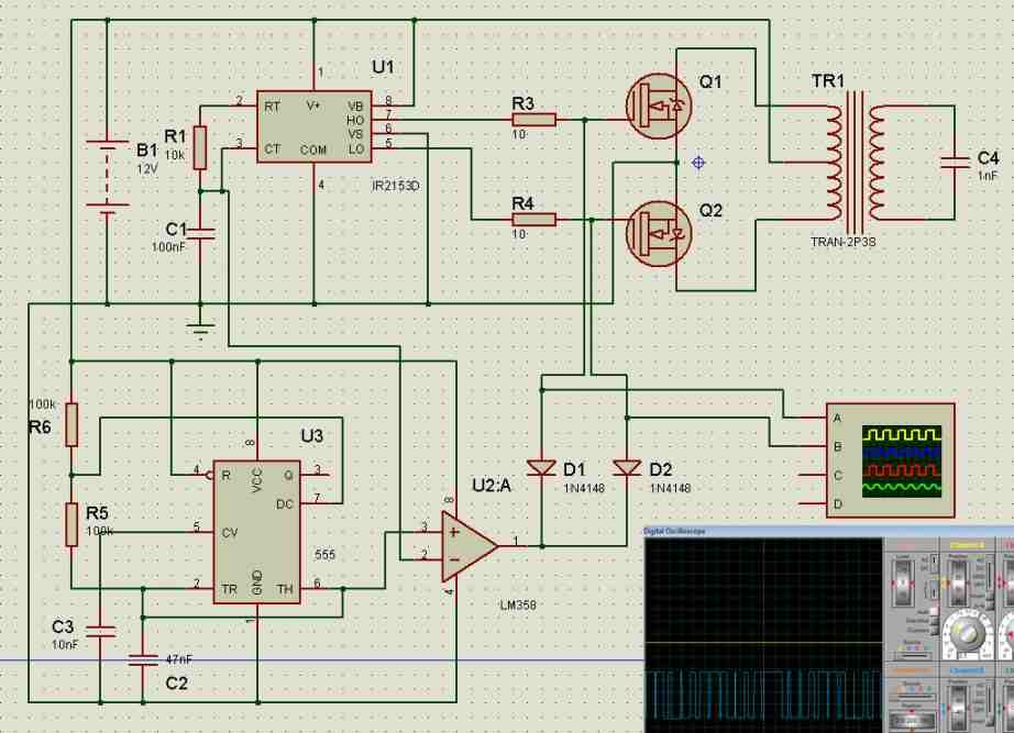
Hi, from where did you get this schematic? this not designed by me. The concept is mine, but not the precise designing.
why it is not including smoothing cap for battery charging path.
smoothing capacitor is not required for battery charging, it only needs to be a DC
Good day Mr Swagatam
Will the above circuit work for 36v brushless dc generator motor
or will there be significiant changes and what would they be.?
Thanks
Hello Wayne, the circuit is intended to produce 220V o 120V AC output, it cannot be used to operate a 36V motor, unless the transformer secondary is appropriately changed to generate 36V DC.
Good day Mr Swagatam
Thx for your reply,sorry i dont think i was very clear,what i was asking is if my input source was
a 36v dc source eg like a wind turbine instead of a 12v or 24v battery.?
would the circuit be simaliar or would it change quite a lot.
? how would i control the output over voltage of the turbine?(brushless dc motor)
I’m a mechanical person trying to learn electronics.
Thx in advance and find your site very informative.
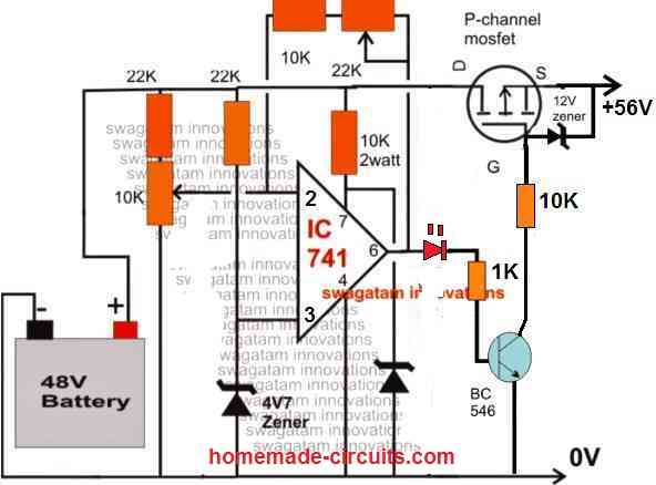
Hello Wayne, yes the inverter will work with 36V DC, provided the transformer is also rated at 36-0-36 V. For controlling the output voltage you will need a shunt regulator as indicated in the following article:
Simple Vertical Axis Wind Turbine Generator Circuit
Please for how long will your inverter last powering a tv, and an electric fan
It will depend on the power rating of the load and the Ah rating of the battery.
I NEED SCHEMATICS FOR 2KW,1.5KW AND 1KW INVERTERS. OR A GUIDE ON WHAT TO DO IN ORDER TO UPGRADE THE LOWER ONES LIKE 500W TO THE SPECIFICATIONS ABOVE. THANKS
You can refer to the following post to know the steps for upgrading a low power inverter to a high power inverter
https://www.homemade-circuits.com/upgrading-low-power-inverter-to-high/
hi Mr: Swagatam
as I understood 10E=10 ohm is it or not?
thanks
riyahi
Hi Khoram, yes that’s correct!
Hi Mr:Swagatam
thanks for your replay.I am studying recommendations to get rid of back emf for best assembly of the circuit because I lost some 3205 without any load.all protection parts(5402 and 4148 and 1 k res. are OK. if you have any idea please help me.
riyahi
Hi Riyahi, I have tested this circuit without any protections except the diodes across drain/source, and still it worked perfectly. I had used IRF540 mosfets. You have provided multiple protections across the mosfets and yet they are burning, so it has to be examined deeply, and cannot be judged without seeing practically.
You can also try adding a 2200uF/25V across the battery terminals, which also helps to eliminate the spikes across the supply lines. Or the best idea would be to use power BJTs instead of mosfets.
hi Mr: Swagatam
thanks for your quick replay i moved the circuit from bread board to PCB .because during the test on breadboard mosfet connected to pin 10 of 4047 damaged. i test the circuit again and inform you the result.
best RGD. riyahi
Hi Riyahi, sure, you can build it on PCB and test the results…I have already tested a 200 watt version and it worked perfectly for me.
Remember to connect diodes across the MOSFET drain and source for extra safety…and also connect a 1k resistor across gate and source of each mosfet for added safety.
hello Mr Swagatam :
i correct my previous comment as below
i designed a 12-012 to 220 volt (500 w) transformer for inverter but practically it is 12-0-11.5 volt has it any effect on 3205 mosfet
thanks very match. riyahi
Hello Riyahi, yes I understood….there won’t be any problem with the mosfets due to the small variation in voltage across one of the winding.
Hello Swagatam ,i did every recommendation like (connecting Diode to 10 ohm ,connecting 1 k between gate and source ) unfortunately MOSFET connected to pin 10 4047(via 10 ohm) fired again .what,s the problem when connection to the car battery ? may it is becaue of bad wending of center tapped of transformer. please inform us of your comment .
thanks
Hello Khoram, did you connect external diodes across drain/source of the mosfets?
The problem is mostly due to sudden reverse surge from the transformer which may be destroying the mosfets.
Another option is to connect a switch between battery positive and the 4047 circuit.
So we connect the battery with the transformer center tap, and then switch ON the IC power. In this way I hope we can prevent the sudden battery current surge to the mosfets.
I hope you have connected the necessary resistors, diodes and capacitor across the IC supply terminals as instructed in the above article.
thanks very much for your quick response
best regards
riyahi
GREAT! I LIKE YOUR TUTORIALS. I WOULD LIKE TO ORDER THE PARTS AND EVERYTHING ABOUT IT FROM YOU INCLUDING THE CIRCUIT DIAGRAMS. HOW MUCH AND HOW WILL I SEND THE MONEY TO YOU? I WANT TO CONSTRUCT THE INVERTER FOR USE.
THANK YOU.
Thank you, but we don’t sell parts or kits at this moment!
hi dear Mr Swagatam
i have send you before comments i don’t know you received or not pls inform me .best rgd khoram riyahi
Hi Khoram, I have answered your question, please check your previous comment!
Thank you very much sir.
I now understand why I realize the converter some did not work because I took any transformer without knowing if it is a 12v transformer, if it is a 24V transformer. So now it’s already clear. Thank you very much for your help
I am glad I could help you Daoud, please keep up the good work!
Good day, sir. Thank you for your reply.
And if now we do the reverse, ie it is possible to replace the transformer of an inverter using a 12v battery by another transformer recovered in a 24V inverter sir?
Please sir can I know some names of software to design simulate electronic schematics? At my level I have proteus and multisim. Thank you for understanding
Hello Daoud, a 24V transformer will not work with a 12V battery. Sorry, I do not use software for verification so cannot suggest on them, I rather prefer testing them practically.
Good evening SIR, I would like to know if we can replace a transformer of an inverter that uses a 12V battery by a transformer recovered in a 24V inverter? As the inverters are different but the transformers each have 3 wire on the secondary and also 2 wire on the primary each
Hello Daoud, that may not be possible because a 24V transformer might have two times higher rated winding than a 12V transformer, which can cause 50% less power output from the transformer when used with a 12V inverter circuit
Good evening sir, thanks for your reply, let me try it again, hope building/ designing it as shown in the diagram will work straight without adding anything?
Dear Sir,
I had made inverter circuit using CD4047 and IAF540’s as per design given by your website and I succeeded also but, At the moment I connected 12 Volts 7 Ah battery I am getting 200 to 203 volts but it starts to reducing and reached 98 to 103 Volts and after a couple minutes output becomes zero. The components 4047-1no,IRF540-2nos,0.01Mfd-1no,100 Ohms-2 nos,10K Pot-1no,IN4007-2 nos, And when i connect 100nF/440 Volts capacitor at the transformer output it becomes zero so I did not connect 100nF. Please support me to make 500 Watts inverter and use one fan and light.
Hello G. kandasami, the problem that you are getting presently may be due to one of the 3 reasons:
1) Your battery has been destroyed due to heavy use
2) Your battery is not properly charged
3) Your MOSFETs are burned.
When are you seeing this problem, is it with an output load connected or without a load?
If it’s without a load then the reason could be as explained above.
You can replace the MOSFET with 50 amp BJTs and check the response. Because MOSFETs are unpredictable and can burn without indications, a BJT is more reliable.
For 12V 500 watt inverter you will need a 12V 100 Ah battery, a 7 Ah battery will not work.
Good day mr Swag thank for your quick responses to every question asked so far. pls my question thus, is what is the exact diode connected in-between the relay coils.
Thank you Godspower, you can use 1N4007 for the diode.
No problem Amos, wish you all the best!
How many relay used this circuit
2 DPDT relays
Eng. swagatam, you are outstanding in electronics systems, your explanations are clear and easily to understood.
I need your support on how i can build a 5 and 7 kilowatt inverter and battery charging circuit diagram for my home.
you are doing an excellent job, please keep it up.
Hi Jonathan, you can select any small inverter design, and simply upgrade its MOSFETs, transformer and battery to get the desired power output…for a 7kva inverter you may have to go for a 48V battery/transformer or a 60 V battery/trafo, the higher the better, ….also the transformer must be rated to handle the specified amount of current, that is 7000 / 48 = 145 amps
A very big thanks to you swagatam, making out time to reply and explain.
i appreciate, thanks once again.
can i use any of your battery charger diagram to build a battery charger
with cut off circuit for
my generator at home.
i like all of your posts. they are very interesting and educative.
they really are.
can i reach u for personal questions if u don’t mind.
Thank you Jonathan and I am glad you liked my posts!
You can select any of the battery charger circuits which you find the most suitable for your specific application.
You can post your queries here, through comments, i’ll try my best to solve it for you!
Good day sir pls I need a pure diagram of the battery charging inverter. I did not understand some symbols
Please specify which symbols you cannot understand?
The article is very good, I am very interested in the topic of inverters. All the best
Thank you for you feedback, glad you liked the post.
I don’t know , is there anything I should add to the circuit, like regulator or increase the resistance
don’t connect the MOSFEts initially. First test whether your IC 4047 is actually oscillating or not. See the datasheet of the IC here
IC 4047 Datasheet, Pinouts, Application Notes
Good sir, the circuit is nice . But after my design the ic spark and spoiled, plz can u help
Hi Amos, 4047 inverter is very basic inverter, and nothing should go wrong. Please see the small 4047 inverter which I built, in the following article….it is a 200 watt inverter and it worked directly at the first attempt. For the MOSFETs I had used IRF540
https://www.homemade-circuits.com/7-simple-inverter-circuits/
hi,thanks a lot for your circuit.I have two questions. is it regular to connect the circuit to car battery without soft start for mosfets? Do we need RC and a Flyback diode for each gate? and second question is about the value of gate’s resistor. I know how to calculate it but i can’t undrestand why in some circuits designer sets wrong value for example instead of irf3205 they use z44 with 100 ohms resistor for gate while it should
be in the range of 10-20 ohms.
Hi, you are most welcome! yes it is normal to connect the battery without a soft start unless the power is too large. But if you wish you can add a soft start by adding diode capacitor network at the gates of each mosfet.
The gate resistor depends on the frequency of the source. For 50 Hz and 60 Hz, any value between 10 ohm and 100 ohm should not have any problems. Similarly mosfet selection strictly depends on the power rating of the inverter, it has nothing to do with the mosfet number
Hi Swagatam,
I want to ask this: What happens when I use a slightly different transformer for example, instead of 9v 0 9v as specified in the diagram and I use 12v 0 12v?
Or instead of a 12v 0 12v as specified in the diagram and i use a 15v 0 15v transformer or 14v 0 14v transformer?
Hi Joe, at 12V you will get 220V when the battery is 12V, but as the battery drops to 11V, the output voltage may drop to 200V, therefore 9-0-9 is recommended which will give maybe 240V when the battery 12 V, and the output may still continue to be 220V when the battery voltage drops to 11V.
Basically at battery 11V also the output must continue to be above 220V….which means the trafo voltage must be rated lower than the battery voltage
Is there any way to make a less wattage transformer e.g. 500watt to build inverter of 1000watt.
That’s not possible, 500 watt can never produce a 1000 watt power
Can I use 7v 0 7v transformer? Will it be too low? I will try and look for 9v 0 9v also?
7-0-7V transformer will work, you can use it…
Can I charge 48 volt battery with 40 volt transformer?
you will need 56V to charge a 48V battery
Hie Swag, wanted to ask how much complex is it to add automatic cut off of battery charger and if it can be done please show me how. And also does the mains responsible for charging only. Can the solar panels also charge when there’s no grid supply. Lastly is there a display circuit that shows input and output voltage and wattage in figures.
If it can be done im Kindly asking you to do that for me
Thanks.
Hi Binus, first you will have to build and test the solar inverter, once you build it and test it successfully after that we can add the battery charger externally….adding the battery charger is not difficult but making the solar inverter can be difficult.
Ing. espero su respusta ,,,,mis saludos y agradecimientos ,,,,, Pregunto…, En la parte de …… .Actualización a inversor de onda sinusoidal modificada ,, se podría alimentar el circuito con un Regulador de 9 volt (7809) el CD4047,, 555 ,, 741 ya que sus alimentaciones están en rango ,,, SEGUN Datasheet
I am a new learner, Please, how many pin has the relay used in the diagram?
Each of the relays have 8 points, since they are DPDT relays…. Please build the inverter without the relay first, if it works only then go for the relay connections.
Ok thanks. I will do that first
I want to know price of these components.
Ing. mis saludos y agradecimientos,,,,,Pregunto…,En la parte de…….Actualización a inversor de onda sinusoidal modificada,,se podría alimentar el circuito con un Regulador de 9 volt (7809) el CD4047,,555,, 741 ya que sus alimentaciones están en rango,,,SEGUN Datasheet
Sir ,how to put charging input on this inverter for charging the battery.
Raj, it is derived from the transformer itself and the mains input….
Thank you sir
Thanks sir. I am referring to the diagram with battery charger
There are two relays RL1, RL2
Both are DPDT
I have connected the panel to the relay stage. But I don’t seems to know how many relay this diagram has. Kindly help
which circuit are you referring to?
Thank you sir. How many legs does the relay has and how many volt is it. And how many volts is the relay coil
Emmanuel, you can see refer to the following article for all the info:
How a Relay Works – How to Connect N/O, N/C Pins
What do I do if I want to reduce that wattage. I mean instead of 500w I will like to do 200 or even 100watts
reduce the wattage of the battery and the transformer accordingly….
Please sir, whi of the diode is the 20amp
D6, near C3
Thank you for your response sir. What of D5.
And in the case of the transformer, is there any alternative to 20-0-20v. I am not able to get that here
Transformer voltage must be lower than the battery voltage, you can try higher values also which will cause proportionate amount of reduction in the output AC
Thank you very much sir. How do I put the indicator for the battery charger in other to know when it’s fully charged.
Can it be charged with solar panel too?
Hi Emanuel, for that you will have to connect an external circuit such as this:
https://www.homemade-circuits.com/battery-full-charge-indicator-circuit/
yes solar charging is also possible, if the panel is rated appropriately
Thank you for the response sir. What of the D5 because I was thinking the initial one was for D5
D5 is for the relay coil operation which can be just a 1N4148 diode, the 20 amp is for D6
Sir how to connect wire for charging the battery(input current in battery)in shown ckt.
Let’s assume I upgraded my inverter up to 2000w, can I use it to iron my clothes, powering my electric cooker and the likes?
Dear Swagatam, I want to congratulate you for your admirable work, since today there are few people who offer their knowledge in this professional and disinterested way solely for the purpose of teaching.
Excuse my inconvenience, maybe you can help me with the pcb layout of this inverter with 500w battery charger
Thank you Clarhem, sorry I do not have the PCB details for this project, you can contact any professional PCB designer for the same, they will surely help you out with some charges.
Sure you can….
hi Swagatam i would like to know how a ups can be transformed into a 12volt to 240volt inverter, currently when pluged just on battery it goes off automatically in 15 mins, how can i make it on continiuosly with being off automatically in 15 mins with 12volt battery use.
Hi Paul, yes it can be done, by removing all the relay changeover stages and by connecting the load directly across the secondary of the transformer.
Hi sir,I have some questions regarding the above articles.
1. With 56k and 0.1uf capacitor, what is the output frequency?
2. For the h bridge,you haven’t provided the down and how to configure it.
3. Sir can you help upgrade the h bridge to use all N channel mosfets using discrete components and cd4047 as our osciliation and incorporate the spwm as in the above article.
Thanks in advance and look forward to your response.
Hi Evans, the frequency will be approximately 50 Hz, but might need some further adjustments to ensure a precise 50 Hz.
The SPWM configuration procedure will be the same as done for the center tap version. Instead of connecting the op amp output directly with the MOSFeT gates, you can add a BjT stage, and used their bases for the SPWM chopping.
For Nchannel H bridge I have already explained the method for SG3525 circuit, you can apply the same comcept here also.
Sir,what kind of adjustments please? Again sir for h bridge,we got the high side and the lower side,how is the connection of the spwm?
Evans, Adjustment of the 56k resistor or the capacitor value…please build the basic design first after that we will try to solve the SPWM
hi sir i have certain doubts in making an inverter with some specific specification for a certain purpose.It will be really useful if i get a chance to contact you through phone or email please.
Hi jefson, I can discuss only through this platform, and not through telephone or email
Again sir,can I use this inveter to power a refrigerator?
Yes if the output wattage of the inverter is calculated according to the fridge requirement
Sir, help me with the inverter battery automatic charger circuit diagram.
Here’s a suitable link you may try:
https://www.homemade-circuits.com/opamp-low-high-battery-charger/
Dear Sir,
I am looking for a sine wave inverter circuit with 48V/72V to 440VAC ( two individual windings of 0-230 with phase shift capacitors also serves) of 2KVA with a relay (Invertor on mode) on technology transfer basis.
This can be based on arduino/pic/sg3524.
Dear Ravi, Sorry, I do not have the sufficient information regarding the specified inverter design, at this moment.
Good day sir, please what are the requirement for designing a 3000watt inverter.
Hi Felix, for upgrading to higher wattage, you only have to add more MOSFETs in parallel, increase supply voltage to the transformer up to 48 V 70 amps, and battery up to 48 V 500 Ah
Please if one wants to construct a 3kva center tap transformer, what will be the size of the copper wire and the number of turns for 240vs.
Dear Swagatam
Re 500W Inverter with charger.
Thanks for you prompt reply. Whist I appreciate that the schematic has some additional components (for safety purposes) not shown in the List of Parts, please would you advise the values of these components, so that I can incorporate them into the circuit.
Many thanks
Mike
Thank you Mike, the values are already given in the subsequent diagrams:

all the resistors are 1/4 watt 5% CFR, capacitors have voltage rating two times more than the battery voltage.
I’d like to build this inverter (without the battery charger, as I plan on using solar power), but I have a problem tying up the components on the schematic with the List of Parts.
Parts List specifies 3 resistors (10 Ohms X 2 and 56k Ohms X 1), but schematic shows 5. Likewise Parts List specifies 2 (0.1 uF and 4700 uF) capacitors, but schematic shows 3.
Would appreciate clarification on those two issues, otherwise, everything else makes sense.
Cheers
Mike
If the schematic shows some extra parts, there’s no harm in adding those. The parts list suggests the bare minimum parts required for building the basic 500 watt inverter, whereas the schematic shows some extra features for ensuring better safety to the circuit.
Why don’t I get 500W with 12V 100Ah battery? I get 1200W I think. What about hot transistors?
With a 100 Ah lead acid battery you shouldn’t try getting 500 watt from 12 V, if you do, you will end up destroying your battery in sometime. With 1200 watt your will destroy your battery in minutes or seconds.
But with Li-ion it is easily possible.
Sir You have computer ups 500VA OR 600VA CIRCUIT DIAGRAM
Manjunath, sorry I do not have this circuit at this moment.
Can I parallel batteries then?
yes you can use batteries in parallel
Thank you very much.
Can I use a 100Ah inverter battery?
with a 12V battery 100 ah will not produce 500 watts.
but why sir ,VxI = 1200w theortically, but does it depends on effeciency and pf of inverter circuit.
a new 12v 7.2Ah vrla battery does not provide enough power, my 5w ac led bulb running for 1-.5hr and battery voltage goes from 13.2v to10.7. ,
kindly provide exact detail for 200w with required battery ah rating. lead acid
Good morning and thanks for these inverter circuit diagrams. I realized the second circuit (inverter using 24V battery), but anytime i switch of the circuit, at least one transistor IRF3205 will be destroyed. I have replaced the transistor many times but i still have the same problème. I have added diode berween the D and S terminals, but the problem remains.
Thanks
Hello, I have checked the 4047 based inverter using IRF540 mosfets, and it worked perfectly for me with a 100 watt load. There are three basic reasons for a mosfet getting burned. 1) if the mosfet is not original, 2) mosfet does not have basic protections 3) Sudden high current surge across drain and source.
The sudden high current situation can be corrected by initially keeping the center tap of the transformer disconnected from the battery supply. Start by powering the IC circuit first, and confirm the frequency output from the IC. Once the frequency output is confirmed, connect the transformer center tap with the battery DC and you should find the inverter working normally. If still the mosfets burns then most probably the mosfets are not good quality.
Thanks you once more, i think it is the quality of the MOSFET transistors as you said. Because i have done different protection methods without success. I will try with different MOSFET types. Thank you.
Sure, no problem, all the best to you!
Can I use 9V battery?
No!
It is because Lead acid batteries are not designed to be discharged at their full Ah rate, they must be discharged at 10% or maximum 20 % of their Ah rate.
You can get more info on this here
Lead Acid Battery Charger Circuits
Note: sorry i posted this query in wrong topic before so posting here
Hi Sir,
Need your help again. You are very knowledgeable and humble person. This earth needs more like you.
Can u tell how we can check efficiency of inverter in general understanding language without going into theory behind it. I m asking for the reason bcoz i have very old 3055 based desi inverter of 500 watt and it running excellent since 2003. Only thing is missing is battery overcharge protection but most of the time charging renaming off bcoz i have sukam mppt solar charge controller of 17amp with 300w solar panel. I do not want to upgrade it to digital microcontroller based only fur the reason old inverter never gone bad in 17 years. Only problem in these years that i had to re solder wires to some led and amp meter one time only. Please suggest ur valuable input wheather its worth to upgrade it with latest technology digital inverter…
Images
https://1drv.ms/u/s!AkqDWegCTCgviUoXPcC6pEByP6rt?e=H77KIy
And one more question what is the best charging current practice ( at always 10% of battery capacity or can use low charging current. I think slow charging increase the battery life and so i use 5-7amp current only..) in case if powercut is about an hour in 24 hour. Battery i have is microteck 150ah. I understand u will be very busy but will feel happy if u reply with ur valuable input.
Thanks Ram, you can check the efficiency by measuring and comparing the V x I of the input 12V supply side of the inverter and V x I of the output 220V side of the inverter.
Best charging current for all lead acid battery is 10%, reducing below this level is not necessary as it may increase the charging time to 20 hours. But yes it will help to increase the life of the battery.
for auto cut off at 14.2V you can try the following circuit

Thank you 🙂
Hi Sir, It’s awesome explanation but I need to know, How we will come to know whether battery charged fully, Is there any led indication?
Thanks
Sidaray
Thanks Sidaray, the simplest way is to add an ammeter in series with the battery positive, when the needle nears the zero volt, it will indicate the battery is fully charged.
Thanks for your good works. Can I add more 3205 mosfets for greater wattage? Thanks
yes you can, it is the MOSFETs, the battery and the transformer that decide the power output.
swagatam sir i want 12v dc 1000w or 1200w power inverter ckt diagrams.
Sree, you can try any inverter design from this website, and upgrade it as per the details presented in this article:
https://www.homemade-circuits.com/upgrading-low-power-inverter-to-high/
Very clean and straight forward project i would like to design, But then how can i add an overload protection to practically work wit this project, Thanks Swagatam.
Thank you, you can add the following concept for overload protection:
https://www.homemade-circuits.com/low-battery-cut-off-and-overload/
Thank you so so much for your reply sir.. Have to finally get a jem in electronic field who solves the problems with efficiency..
You are welcome KGopi
Please I need answers because I wanna couple a 130w solar panel with 650VA UPS, will this work sir
I have request to you sir, pls upload configuration and design of current source inverter
Thank you Amar, I am studying it, and if possible I’ll post a related article soon.
Sir i have 3kw /400v Dc on-grid Solar system… when grid power switches off during peak hours of sunshine ongrid solar also switches off.. so energy from solar system getting wasted…so during this switched off time can we have another solar inverter without battery system to run atleast 2000w power system.. Night i don’t need power
Yes you can use the solar power by diverting it through a relay changeover. This relay should be powered from grid voltage, so while grid is available, the relay contacts keep the external inverter disconnected from the solar power. When the grid fails, the relay contacts switch over and connect the external inverter with the solar panel.
Thank you somuch for your Replay Sir.. without battery can i use solar energy directly .. just by converting to 220v AC from 3kw..400v DC
Hi K Gopi, yes that may be possible if the transformer is correctly designed for converting the 400 V into 220 V
Hi
I need a protection circuit that will keep an appliance switched off during load shedding and only switch on when the power comes back on and is stable at 240v.
Kind regards.
Hi, you can try the concept presented in the following article
https://www.homemade-circuits.com/mains-high-low-voltage-protection/
Hi
Thanks for the reply appreciate it. Our line voltage is 240v and when we have load shedding it switches back on with over 300v. I need a circuit that will switch the appliances back on when the voltage stabilizes at 240v.
Regards
Hi, the linked circuit will do exactly that! It will never switch ON the appliance with the wrong voltage
good evening sir,i would like to know the formulas for calculating ic 4047 frequency
Yusuf, you can refer to this article:
https://www.homemade-circuits.com/ic-4047-datasheet-pinouts-application/
hi sir, can you help me how to make a 500 watts inverter, 12v DC to 220v AC, 60H, and modified square waves? can you make a circuit for me and its layout on pcb?
Hi lloyd, you can try the following concept
https://www.homemade-circuits.com/1500-watt-pwm-sinewave-inverter-circuit/
Hi engineers,I have done this project is good,I even went further ahead by making it an automatic inverter charger. My problem is that my batteries don’t get charged fully since inverters with pwm usually have their transformer voltages halved or 2/3 of the same,any help on how I can improve the charging speed will be appreciated.
Thank you Evans, I have already addressed this issue in the article, under battery MOSFET, transformer selection….
Hello Sir I have 7805ic and IRF 540 mosfet can I use it to make this inverter?
Bios, 7805 will not work, you will have to use 7812, IRF540 can be tried, it might work, but mount them on large heatsinks
can I have the layout in Pcb of the modified sine wave inverter circuit?
and what is the orange one in the circuit represents?
I’ve been looking at various inverter circuit designs on the ‘net and youtube. You have done a very good job explaining your circuits and detailing how they work. As you know power inverters can be pricey for anything 500 watts and above, so your designs now seem obtainable to actually making my own.
What would be required to build a 2000w or 5000w power inverters? Does your circuit design change?
How would you go about calculating the components specs for a these higher wattage inverters?
Thank you for posting your circuits and your comprehensive yet well written explanation.
-Martin
Glad you liked it, I have explained the process of calculating the transformer and the MOSfET for upgrading the inverter to any desired power level.
I really appreciate this effort.
Am new in this website and am always looking forward to understanding how a smps circuit oscillates, cause am a 17yr old beginner in electronics
Thank you, I appreciate your interest…keep up the good work
excellent design
Hi,I like the design. What can be done to the circuit so that I can use a two wire transformer at the primary side and also instead of using the relays I just use the same mosfets for inverter and battery charging? I’ll appreciate a schematic diagram if possible.
Hi, I’ll try to update it soon
Hello sir swagatam,how did it go,did you find anything good for an update about an inverter circuit diagram using a transformer without centre tap?
Hi Evans, I have updated a full bridge version at the end of the post. You can check it out…
Thank you sir for your kindness,now my other questions are;
1. Can we use N channel mosfets only with the same circuit,any update please? Coz with high currents, I will be forced to use a big number of p channel mosfets which Leeds to high cost and space limitations.
2. What could be the current ratings of RL 2 & RL 3 if for instance I built a 24vdc/220vac/6000w inverter?
Sorry had a typing error,I meant cd4047
Thank you sir for your response. So if I integrate a boostraping network then can use cd4047 as the oscillator? True or not? Any clarifications?
It is possible with bootstrapping introduced with any oscillator.
Evans, N-channel cannot be used without specialized ICs or a bootstrapping network
Sir pls upload current source inverter circuit and design configuration of it.
I will surely try…
Will appreciate
Is 24v battery is available
I liked the circuit. I only wish it had a power supply for its regulation both in frequency and in output voltage. Thank you very much
Thank you, if possible I’ll try to update the details in the article.
Hello my lecturer, I just want u to help me abit on the inverter circuit. My customer brought me an inverter charger 800 VA and it’s motherboard is completely damaged. Can u refer me to one of your sine wave inverter charger that I can replace with it pliz. 12v 800VA I beg
Hello Morris, most of the inverters circuits explained in this blog use center tap transformer which cannot be replaced with the mother board of your inverter, unless your inverter is also a center tap type.
And is the second circuit in the 7 modified sine wave inverter good to use if I use 8 output MOSFETs to match the size of the transformer and get altleast 800va or equivalent the i look for a separate charge? Advice I beg. Thanks.
yes the second circuit is good, will give you a decent modified sine wave which is quite equal to a pure sine wave. Commercial inverters never use center tap transformer for their inverter designs, as far as I know.
Ok sir. So for the lighting and tv’s it will work perfectly…the second modified sine wave inverter? So I will use 10pcs if MOSFETs…….the ones in ths damaged motherboard (55nf06)? Many thanks sir.
You will have to connect a few 1uF/400V capacitors at the output of the transformer to get a pure sine wave like response which will suit most equipment. You can use 10 mosfets in parallel on ech channel.
Ok my transformer is a center tap wire can I use the second last modified sine wave circuit and use 8 mosfet output to match the transformer size and get the best output wattage or that 800VA
Yes you can do that, but build it step wise. First build the basic inverter, test and confirm, then add the sine wave section, test and confirm and then finally build the battery charger stage, again test and confirm. You will need an oscilloscope for all this.
But sir i don’t an oscilloscope, if build it the way u drew it as I can see without that oscilloscope will it work? Secondly, if not can I use the the second circuit in your 7 modified sine wave inverter and use the 8 MOSFETs to get the equivalent 800VA. The inverter is luminous 12v 800va from India. Advise
Without oscilloscope how will you test the waveforms?….please do not build without an oscilloscope.
Thanks for your response sir, I appreciate a lot how u advise. Lastly, in this post the last circuit using transformer without center tap wire is it also a modified sine wave inverter at just an ordinary but does that require an oscilloscope to verify its output wave form? That’s all I have sir thanks in advance.
You are welcome Morris, the last circuit is an ordinary square wave inverter not a modified one. Oscilloscope is recommended for all inverters, to ensure that the waveform is correctly verified.
Hello is the 2nd last circuit in this article best to use in my shop as backup when there is a power grid failure? Two, can I u irf3205 being it’s an inverter charger? Thanks
You can use it but only if you have understood the design perfectly.You can use IRF3205 for the inverter
And can I use two 4 irf3205 or 2 are just enough for the the 500w inverter charger?
I think 4 will be better, 2 on each side, and mounted on large heatsinks. Make sure to put protection diodes across darin/source of the parallel mosfets. One common diode across each parallel set will be enough.
Ok sir. Now with 2nd last modified inverter sine wave inverter charger in this article. If u compare it with the second circuit in your 7 modified sine wave inverter in the other article which one is best and efficient I can use in my shop?
The second last circuit above is more efficient but more complex to build.
Ok sir, but as an expert in this field if I avoid the charger part of this circuit in ths article as use it as an inverter alone. It still stands the best compared to the first two circuits in the 7 modified sine wave inverter? Advise sir, I want to pick one. Thanks in advance.
Ok sir. Let me just build it and use it in my shop as more efficient one as you told me. Hope it will perform well. Thank u very much
Sure, no problem.
So if I make it the way it is to charge the battery I still need an oscilloscope to verify its vave form?
oscilloscope has nothing to do with battery charging, the scope is needed only to verify the inverter output waveform
Sir I don’t have oscilloscope in my shop. Can i jst use it pliz or switch to the first two circuit in the 7 modified sine wave inverter? Advise
Without an oscilloscope it is not possible to complete the second last design, in that you case you can build the second design from the 7 modified article. Make sure to check the video to see the waveform details.
Morris, yes the second last circuit is more efficient but you will require an oscilloscope for testing the waveform. In the 7 modified article, a oscilloscope may not be required.
Pls sir can u give me the pure diagram of the inverter with battery charging. Pls dont use symbols I didn’t understand it well
hi dear Mr Swagatam
i prepare circuit contains 4047 and 3205 and 500watt transformer test with 12 volt adapter 3A is and 9 watt load OK but connecting it to battery causes MOSFET connected to pin 10 of 4047 (via) 10 ohm without load broken . please inform me what is wrong.
bet regards ; KHORAM RIYAHI
Dear Swagatam
is there any limitation for battery power cable and power line because of transformer harmonic radiation.
best regards
riyahi
Hello Riyahi, I am sorry, I have not yet investigated this issue, so not sure about the facts!
hello Mr Swagatam :
i designed a 12-012 to 220 volt (500 w) for inverter but practically it is 12-0-11.5 volt has it any effect on 3205 mosfet
thanks very match. riyahi
Hello riyahi, the difference in voltage across the transformer winding will have no effect on the mosfet behavior. You can use it safely…
Hi Khoram, it could be due to high current reverse spike from the transformer.
Please go through the following article, and try to include all the measures that is indicated in all the single MOSFET diagrams.
https://www.homemade-circuits.com/mosfet-protection-basics-explained-is/
Also for the IC 4047 did you apply the mentioned protections. Make sure to apply at least the following: