In this tutorial I will explain how to do basic Arduino programming through example codes and sample programs. This tutorial can be an extremely valuable course for all the newcomers who wish to grasp the basics through easy, understandable language.
Introduction
According to wikipedia a microcontroller is equivalent to a mini computer built inside a single IC chip, having its own core processor, programmable inputs, memory and output peripherals.
A microcontroller becomes so useful for a user since it offers a built-in processor, memory and input/output ports (also called GPIO or general purpose input/output pins) which we can be controlled by the user as per any desired specifications.
In this tutorial we will work with an Arduino Uno board for learning and testing the programs. For testing and integrating hardware assembly we will use a breadboard.
Now let's move quickly and learn how to get started with an Arduino programming.
1.2 Installing the Software (Windows)
For this you will need access to internet, which obviously you'd be having in your computer. Please go to the following link and download the IDE software:
Windows ZIP file for non admin install
After downloading you will find the Arduino setup icon in the download folder, which would look like this:
Once you get this, you can simply double click on it and install the Arduino the Integrated Development Environment (IDE) in your computer. The complete process can be visualized in the following video:
1.4 Starting with our First Circuit
Before we start learning the actual programming techniques, for any newbie it would be useful to begin with a basic component such as an LED, and understand how to connect it with an Arduino.
As we know an LED is a light emitting diode which has a polarity and will not illuminate if it is not connected with the right supply poles.
Another aspect with LEDs is that these devices work with low current and may get damaged instantly if an appropriately calculated resistor is not included in series with one of its pins.
As a rule of thumb, a 330 ohm 1/4 watt is quite ideal for every 5V rise in the supply input to limit the current to a required safe level. Therefore for 5V it may be 330 ohms, for 10V it may be 680 ohms and so on.
Using Breadboard for the Assembly
Please make sure that you know how to use a breadboard prior to trying the tutorial explained in this chapter, since we would be using a breadboard for all the experiments here.
The basic LED connection setup can be witnessed below:
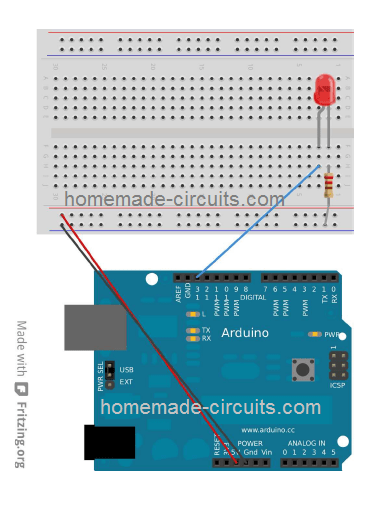
You can see 3 basic components above:
- A 5mm, 20mA LED
- a 330 ohm 1/4 watt resistor
- An Arduino Board
Just assemble the system as per the diagram.
Next, plug in the 5V from computer USB to the Arduino. As soon as you do this you will see the LED lighting up.
I know that's pretty basic, but it's always good to start from the scratch. Rest assured things will start getting more and more interesting as we move ahead.
1.5 Controlling LED with Arduino
Now we'll learn how to control an LED with an Arduino program.
To write a program we must have at least 2 functions in each program.
A function may be understood as a series of programming statements that may be assigned with a name, as given below:
- setup() this is called or executed during the start of the program.
- loop() this is called or executed repetitively during the entire operational period of the Arduino.
Therefore, although it may have no practical functionality, technically a shortest legitimate Arduino program can be written as:
Simplest Program
void setup()

{

}

void loop()

{

}
You might have noticed that in many of the programming languages, the system begins by showing a simple print, "Hello, World" on the display screen
The electronic equivalent for this phrase in microcontroller interpretation is to blink an LED ON and OFF.
This is the most basic program that one can write and implement to indicate a correct functioning of the system.
We'll try to implement and understand the procedure through the following piece of code:
Listing 1.2: led1/led1.pde
const int kPinLed = 13;

void setup()

{

pinMode(kPinLed, OUTPUT);

}

void loop()

{

digitalWrite(kPinLed, HIGH);

delay(500);

digitalWrite(kPinLed, LOW);

delay(500);

}
OK, now I will explain what each line of the code means and how it works to execute the function:
const int kPinLed = 13;
This works like a constant which allows us to use it during the complete programming course, without the need of using the actual value which is set against it.
As per the standard rules such constants are recognized with the starting letter k. Although this is not compulsory, it makes things clearer and easily understandable whenever you feel like going through the code details.
void setup()

{

pinMode(kPinLed, OUTPUT);

}
This code configures the specific pin to which our LED is hooked up. In other words, the code tells the Arduino to control the "writing" aspect on this pin, instead of "reading" it.
void loop()

{

digitalWrite(kPinLed, HIGH);

delay(500);

digitalWrite(kPinLed, LOW);

delay(500);

}
The above lines indicate the actual execution of the application. The code begins by writing and rendering a HIGH out on the relevant LED connection, turning the LED ON.
Here, the term HIGH simply means getting +5V on the concerned pin of the Arduino. The complementing term LOW simply indicates a zero or 0V on the designated pin.
Next, we call delay() whose function is to create a delay through milliseconds (1/1000th of a second). Since the figure 500 is entered, the delay implemented is going to be for a 1/2 second.
As soon as this 1/2 second is lapsed, the next line is executed which turns the LED OFF with the LOW term on the same pin.
The subsequent line yet again generates the 1/2 second delay, in order to allow the LED to remain OFF for 1/2 seconds.
And the process continues infinitely by the execution of the lines of code, a long as the Arduino is kept powered.
Before proceeding to the next level, I would recommend you to please program the above code and check whether you are able to implement the LED ON/OF sequence correctly or not.
Since the default LED in Arduino is connected with pin#13, it should immediately respond to the above program and begin flashing. However, if you find your external LED not flashing then there could be a connection fault with your LED, you may try reversing the polarity of your LED and hopefully see it blinking too.
You can play with the delay time by altering the "500" figure to some other value and find the LED "listening" to the commands and causing it to flash as per the specified delay values.
But remember, if you see the LED not flashing with a constant 1 second rate, regardless of your delay time alteration, that may indicate the code is not working due to some mistake. Because by default the Arduino will be programmed with a 1 second flashing rate. Therefore this rate must get varied by your code for confirming its correct working.
1.7 Comments
The lines of codes which we understood above were specifically written for the computer software.
However, in order to ensure that the user is able to refer the meaning of the lines and understand them, it often may be useful and sensible to write the explanation beside the desired lines of codes.
These are called comments which are written for human or user reference only, and are coded to enable the computers to ignore it safely.
The language of these comments are written with a couple of formats:
- The block style of comment, wherein the comment description is enclosed under the start symbol /* and ending symbol */
- This doesn't have to restrict in one line rather could be extended to the next subsequent lines depending on the length of the comment or the description, as shown in the following example:
/* This is a comment */
/* So is this */
/* And
* this
* as
* well */
For writing quick single line description for a comment, two slash // symbol at the start becomes sufficient. This tells the computer that this line has nothing to do with the actual code, and must be ignored. For example:
// This is a comment which computers will ignore.
Here's an example for reference:
/*

* Program Name: Blink

* Author: Alan Smith

* Description:

* Turns an LED on for one half second, then off for one half second repeatedly.

*/
/* Pin Definitions */

const int kPinLed = 13;

/*

* Function Name: setup

* Purpose: Run once when the system powers up.

*/

void setup()

{

pinMode(kPinLed, OUTPUT);

}

/*

* Function name: loop

* Purpose: Runs over and over again, as long as the Arduino has power

*/

void loop()

{

digitalWrite(kPinLed, HIGH);

delay(500);

digitalWrite(kPinLed, LOW);

delay(500);

}
1.8 Troubleshooting
If you find your program showing an "error" while compiling, or some other issue, the following tips will probably help you to recheck your code get rid of the hurdle.
- Your program language will be case sensitive. For example the expression myVar cannot be written as MyVar.
- All kinds white spaces that may be executed by your keyboard typing, is ultimately rendered as a single space, and it is visible or understood only by you, the computer will not take this into account. Put simply, free spaces of any kind will not have any effect on the code results.
- Each block of code must be enclosed with left and right curly brackets, "{" and "}"
- Number digits should not be separated with commas. For example, 1000 may not be written as 1,000.
- Every code line enclosed between the curly brackets must finish with a semicolon ;
Creating Interesting LED Light Sequence with Arduino
In our previous chapter I will explained how to blink an LED ON/OFF continuously with a constant delay rate.
Now we'll learn how different delay patterns could be executed on the same LED by upgrading the program code.
We won't be using an external LED, rather be using the default LED built into the Arduino board at pin#13. You can find this tiny SMD LED just behind the USB connector.
2.2 Understanding IF Statements
In this section we'll learn how control structures enable us to run individual codes, and sometime even repetitively, as required.
The statement if becomes the 1st control structure. The following implementation shows how it is used:
const int kPinLed = 13;

void setup()

{

pinMode(kPinLed, OUTPUT);

}

int delayTime = 1000;

void loop()

{

delayTime = delayTime - 100;

if(delayTime <= 0){ // If the delay time is zero or less, reset it.

delayTime = 1000;

}

digitalWrite(kPinLed, HIGH);

delay(delayTime);

digitalWrite(kPinLed, LOW);

delay(delayTime);

}
We'll try to understand the above code step-wise and learn how this can used for other similar executions.
The codes between 1st and 7th line are exactly similar to our initial program.
The first modification actually happens on the 8th line.
int delayTime = 1000;
You can find this to be similar to the code on the 1st line, barring fact that it is missing the term const.
This is simply because, this code is not a constant. Instead this is defined as a variable, which has the property of a variable value in the course of the programming.
In the above example you can see that this variable is attributed with a value of 1000. Remember, such variables that are enclosed within curly brackets has to be strictly written within pairs of curly brackets only, and are referred to as "local" variables.
Alternatively, variables which are supposed to be outside curly brackets, like the one we are discussing now are recognized as "global", and could be executed just about anywhere within a program code.
Moving ahead, you can see that codes between line 9 and 11 are also similar to the first program, nonetheless things start to get interesting after line 11. Let's see how!
delayTime = delayTime - 100;
In this code we see that the default value of the delayTime is being modified by subtracting 100 from it.
Meaning 100 is deducted from its initial value of 1000, providing it a new value of 900.
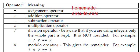
Through the following image we will try to comprehend a few of the Math operators used in Arduino language.
Now let's assess the codes between line 13 an 15.
if(delayTime <= 0){  // If the delay time is zero or less, reset it.

delayTime = 1000;

}
The main objective of the above piece of code is to ensures that the LED continues blinking without any interruption.
Due to the fact that 100 is being deducted from the original delayTime, it prevents the LED blinking from reaching zero and allows the blinking to go on continuously.
The following image shows a few comparison operators that we'd use in our codes:

In our above code, we could have tested the code to be if(delayTime == 0).
However, because being negative figure can be equally bad, we didn't go for it, and this is a recommended practice.
Think what could have been the outcome if we'd tried to deduct 300 instead of 100 from delayTime?
So now you may have realized that if the delayTime is written as less or equal to zero, then the delay time would be set back to original figure 1000.
digitalWrite(kPinLed, HIGH);

delay(delayTime);

digitalWrite(kPinLed, LOW);

delay(delayTime);
The last 4 lines of the code as shown above become responsible for turning the LED ON/OFF, ON/OFF continuously.
Here you can clearly notice that instead of using a number of figure, we have used a variable for assigning the delay time so that we can adjust it as we want during the operational period of the code. That's cool, right?
2.3 ELSE Statements
Here I will explain why and how an if term may have a clause else so that it decide the situation in case if statement is false.
I am sorry if that sounds too confusing, don't worry, we'll try to understand it with the following example:
const int kPinLed = 13;

void setup()

{

pinMode(kPinLed, OUTPUT);

}

int delayTime = 1000;

void loop()

{

if(delayTime <= 100){ // If it is less than or equal to 100, reset it

delayTime = 1000;

}

else{

delayTime = delayTime - 100;

}

digitalWrite(kPinLed, HIGH);

delay(delayTime);

digitalWrite(kPinLed, LOW);

delay(delayTime);

}
In the above you can well see that in the 10th line code is only executed when the delayTime is less or equal to 100, if not then the code in the 13th line is executed, but both together can never happen, either the 10th line or the 13th line code will be implemented, never both.
You may have noticed that unlike of what we did in our previous section 2.2, here we did not compare with 0, rather compared with 100. This is because in this example compared BEFORE we subtracted 100, contrarily in section 2.2, we compared AFTER we subtracted. Can you tell what could have happened if we'd compared 0 instead of 100?
2.4 WHILE statements
A while statement is quite similar to if statement, except the truth that it causes repeated execution to a block of code (which may be between curly brackets) for so long the conditions are applicable, and this works without an else statement.
The following example will help you to understand this better
const int kPinLed = 13;

void setup()

{

pinMode(kPinLed, OUTPUT);

}

int delayTime = 1000;

void loop()

{

while(delayTime > 0){ // while delayTime is greater than 0

digitalWrite(kPinLed, HIGH);

delay(delayTime);

digitalWrite(kPinLed, LOW);

delay(delayTime);

delayTime = delayTime - 100;

}

while(delayTime < 1000){ // while delayTime is less than 1000

delayTime = delayTime + 100; // do this first so we don’t have a loop with delayTime = 0

digitalWrite(kPinLed, HIGH);

delay(delayTime);

digitalWrite(kPinLed, LOW);

delay(delayTime);

}

}
Can you guess what the above code is programmed to do? Well, it is designed to blink the LED faster and then slower.
2.5 What is true and false?
In programming language, false refers to zero (0). Actually "true" is not used, instead it is assumed that when nothing is false, then all that is included is true.
It looks little strange however it does the job pretty nicely.
We'll try to grasp the situation through the following example.
You may sometimes come across a code as given below:
while (1){

digitalWrite(kPinLed, HIGH);

delay(100);

digitalWrite(kPinLed, LOW);

delay(100);

}
This is coded looks like the LED execution will keep cycling forever, as long power is available.
However, one downside of this type of code could arise when accidentally the user applies a = instead of ==.
I'm sure you already know that = signifies an assignment, meaning it is used to designate a selected value to a variable, while a == is used for enforcing a test if the value was same.
For example suppose you yo required an LED to flash with a sequentially speeding pattern and repetitively, but incorrectly used an = instead of ==.
The code would then appear as this:
int delayTime = 1000;

void loop()

{

if(delayTime = 0){ // WRONG!!! the = should have been ==

delayTime = 1000;

}

digitalWrite(kPinLed, HIGH);

delay(delayTime);

digitalWrite(kPinLed, LOW);

delay(delayTime);

delayTime = delayTime - 100;

}
The mistake will assign 0 to delayTime, and lead to the if statement to check whether 0 was true or not. Since 0 refers to false, it will think it isn't true, and will stop the enforcing of the delayTime = 1000, but instead the function delayTime is held at 0 during the course of the loop().
This looks very undesirable!!
So, always double check your program to make sure you haven't made any such silly mistakes.
2.6 Combinations
Sometimes you may feel the need of testing multiple things together. Like, you may want to examine if a variable was between two numbers. While this can be implemented using the if statement multiple number of times, it may be more convenient to use logical combinations for better and easier reading.
Implementing combinations on logical terms could be done with 3 methods, as shown in the following table:
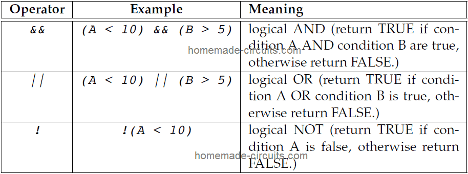
It would be interesting to know that the NOT operator can work as a switcher for a variable which may be designated to be either true or false (or LOW or HIGH).
The following example illustrates the condition:
int ledState = LOW;

void loop()

{

ledState = !ledState; // toggle value of ledState

digitalWrite(kPinLed, ledState);

delay(1000);

}
Here the ledState will be LOW, and subsequently as soon as ledState = !ledState, it will turn HIGH. The following loop will cause ledState to be HIGH when ledState = !ledState is LOW.
2.7 FOR statements
Now I will try to explain about another control structure which is a for loop. This can be very handy when you'd want to implement something several number of times.
So I will explain this with the following example:
const int kPinLed = 13;

void setup()

{

pinMode(kPinLed, OUTPUT);

}

void loop()

{

for(int i = 0; i < 4; i++){

digitalWrite(kPinLed, HIGH);

delay(200);

digitalWrite(kPinLed, LOW);

delay(200);

}

delay(1000); // 1 second

}
You can find something unique in the line with for.
It is the code i++?. This is useful for programmers who are rather lazy and want to implement coding through convenient shortcuts 🙂
The above term is known as compound operators, since they do the job of combining one assignment operator with another assignment operator. The most popular of these can be visualized in the following table:

You will find that there are 3 sub-statements in a for statement. It is structured as shown below:
for (statement1;condition;statement2){

// statements

}
The statement#1 occurs right at the beginning and just once. The condition is tested each time during the course of the loop. Whenever it is true inside the curly brackets, the subsequent statement#2 gets enforced. In case of a false, the system jumps to the next block of code.
Connecting More LEDs
OK, now we'll see how we can connect more number of LEds for getting more interesting effects.
Please connect the LEDs and the Arduino as shown below. The red wire is actually not necessary, but since it is always a good idea to have both the supply rails included in the breadboard the set up makes sense.
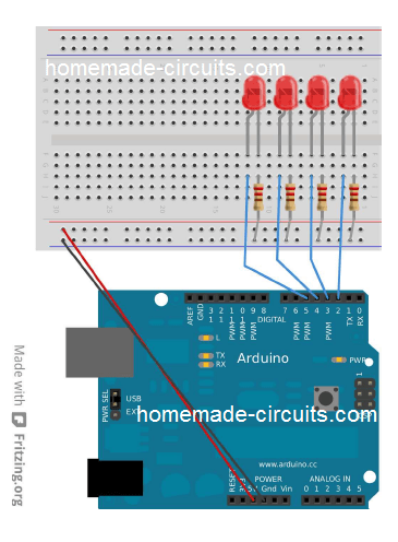
Now let's fix a program which will enable us to check whether our hardware is correctly configured or not.
It is always recommended to code and execute small bits of programs step wise to check if the respective hardwares are wired correctly or not.
This helps troubleshooting a possible error quickly.
The code example below provides LED 2 to 5 a specific pattern by turning them one after the other in a cyclic manner.
const int kPinLed1 = 2;

const int kPinLed2 = 3;

const int kPinLed3 = 4;

const int kPinLed4 = 5;

void setup()

{

pinMode(kPinLed1, OUTPUT);

pinMode(kPinLed2, OUTPUT);

pinMode(kPinLed3, OUTPUT);

pinMode(kPinLed4, OUTPUT);

}

void loop()

{

// turn on each of the LEDs in order

digitalWrite(kPinLed1, HIGH);

delay(100);

digitalWrite(kPinLed2, HIGH);

delay(100);

digitalWrite(kPinLed3, HIGH);

delay(100);

digitalWrite(kPinLed4, HIGH);

delay(100);

// turn off each of the LEDs in order

digitalWrite(kPinLed1, LOW);

delay(100);

digitalWrite(kPinLed2, LOW);

delay(100);

digitalWrite(kPinLed3, LOW);

delay(100);

digitalWrite(kPinLed4, LOW);

}
As you may notice, there's nothing wrong with the code, except the fact that it looks long and therefore prone to mistakes.
Of course there are better ways to write the above code, the following section will reveal it.
2.9 Introducing Arrays
Arrays can be a group of variables which can be indexed with index numbers. The following example will help us to understand it better.
const int k_numLEDs = 4;

const int kPinLeds[k_numLEDs] = {2,3,4,5}; // LEDs connected to pins 2-5

void setup()

{

for(int i = 0; i < k_numLEDs; i++){

pinMode(kPinLeds[i], OUTPUT);

}

}

void loop()

{

for(int i = 0; i < k_numLEDs; i++){

digitalWrite(kPinLeds[i], HIGH);

delay(100);

}

for(int i = k_numLEDs - 1; i >= 0; i--){

digitalWrite(kPinLeds[i], LOW);

delay(100);

}

}
OK, now let's go through each section and understand how they actually work.
const int k_numLEDs = 4;
The above code defines how many maximum elements we are supposed to have in the array. This code helps us in the subsequent sections to ensure that everything is written within an array and nothing once the array ends.
const int kPinLeds[k_numLEDs] = {2,3,4,5}; // LEDs connected to pins 2-5
In this next line we set up the array structure. The numbers inside the bracket indicate the number of elements in the array. Although, the actual quantity could have been written, writing as constants works better. The values can be normally seen inside the bracket with commas and designate the values to the array.
When you find an array indexed with the number 0, this indicates the very first element in the array, as shown in the code: k_LEDPins is k_LEDPins[0].
Similarly the last element will be shown as k_LEDPins[3], since the count from0 to 3 is 4.
void setup()

{

for(int i = 0; i < k_numLEDs; i++){

pinMode(kPinLeds[i], OUTPUT);

}

}
The above code shows the use of loop for proceeding through each array elements and for setting them as OUTPUTS. We implement square brackets along with the index to reach each of the elements in the array.
if you are wondering whether it is possible to use pin#2 to pin#5 without arrays, the answer is yes, it is possible. But in this example it is not done because we did not it in that way. In the following sections you can eliminate the array approach if the selected output pins are not in line.
Moving ahead, let's see what the next block of code does:
for(int i = 0; i < k_numLEDs; i++){

digitalWrite(kPinLeds[i], HIGH);

delay(100);

}
Here the code proceeds through each of the LED to switch them ON sequentially with a gap or delay of 100 millisecond.
for(int i = k_numLEDs - 1; i >= 0; i--){

digitalWrite(kPinLeds[i], LOW);

delay(100);

}
Using the above code exhibits how the application of for loop could be used to move through the loop even in the reverse order.
It begins from k_numLEDs - 1 because arrays are zero indexed. We don't start from k_LEDPins[4] because that would result in crossing the finish of the array.
The code uses >=0 to check so that the first element at index 0 is not missed or ignored.
Chapter 3
What’s an Input
So are I will explained how to operate things using Arduino. In this chapter I will elucidate how to sense the real world by interfacing inputs from external parameters.
3.1 Using Pushbuttons
We all know what a push-button is and how it works. It is a kind of switch or button which connects a signal from one circuit stage to another momentarily while it is in the depressed condition, and breaks the signal when released.
3.1.1 One button and an LED
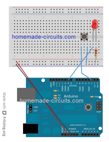
We'll connect the Arduino with a push-button with Arduino as per the above shown details and learn the basic working and implementation of the set up.
The indicated push button which is also called a micro switch push button, have 4 pins in total (2 pairs on each side). When pushed, each pair of pins are joined internally and a enable a connection or conduction across them.
In this example we are using just one pair of these pins or contacts, the other pair is irrelevant and therefore is ignored.
Let's proceed are applying the following code and check out it working!
const int kPinButton1 = 2;

const int kPinLed = 9;

void setup()

{

pinMode(kPinButton1, INPUT);

digitalWrite(kPinButton1, HIGH); // turn on pull-up resistor

pinMode(kPinLed, OUTPUT);

}

void loop()

{

if(digitalRead(kPinButton1) == LOW){

digitalWrite(kPinLed, HIGH);

}

else{

digitalWrite(kPinLed, LOW);

}

}
You may find a few things which look unusual here. Let's figure them out step wise.
void setup()

{

pinMode(kPinButton1, INPUT);

digitalWrite(kPinButton1, HIGH); // turn on pull-up resistor

pinMode(kPinLed, OUTPUT);

}
The first thing we do is fix the buttonPin as the INPUT. Well that's quite basic, I know.
Next, we assign HIGH to the INPUT pin. You a wonder, how it may be possible to write anything at the input? Sure, this may be interesting.
Actually, assigning a HIGH to an Arduino input toggles an internal 20k Ohm pull-up resistor ON (a LOW on this pin toggles it OFF).
Another question that you may is what's a pull-up resistor. I have covered a comprehensive post on pull-up resistors which you learn it here.
OK, moving on, now let's look at the main loop code:
void loop()

{

if(digitalRead(kPinButton1) == LOW){

digitalWrite(kPinLed, HIGH);

}

else{

digitalWrite(kPinLed, LOW);

}

}
When you press the push button, the wired pin gets connected to ground, which renders a LOW to that pin. And while in the unpressed condition the same pin is held at HIGH or +5V via the 20K internal pull-up resistor.
Here we want the Arduino to light up the LED when the push button is pressed (LOW), therefore we write HIGH for the output for every response of a LOW from the push button, while it is pressed.
3.1.2 Two buttons and an LED
Well, you may wonder the above shown action could have been done without an Arduino too. I understand, however this a steeping stone to learn how push button could be used with Arduno.
Until this point, we have studied writing codes for either switch ON (HIGH) or switching OFF (LOW) an LED.
Now let's see how brightness of LED could be controlled with an Arduino.
It may be done using two methods:
- By restricting the amount of current to the LED
- By using PWM or pulse width modulation, in which supply to the LED is switched ON/OFF at some desired rate very rapidly, producing a average illumination whose intensity would depend on the PWM.
In an Arduino board PWM support is available on pins marked with a tilde(~), which are pins 3, 4,5,9,10 and 11) at 500Hz (500 times a second). The user is able to provide any value between 0 and 255, where 0 refers to no HIGH or no +5V, and 255 tells Arduino to get a HIGH or +5V all the time. For initiating these commands you will have to access the analogWrite() with the desired value.
You may assume PWM to be x/255 where x is the desired value you want to send via analogWrite().
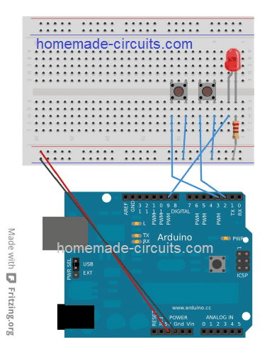
Setup the Arduino and other parameters as shown above.
const int kPinButton1 = 2;

const int kPinButton2 = 3;

const int kPinLed = 9;

void setup()

{

pinMode(kPinButton1, INPUT);

pinMode(kPinButton2, INPUT);

pinMode(kPinLed, OUTPUT);

digitalWrite(kPinButton1, HIGH); // turn on pullup resistor

digitalWrite(kPinButton2, HIGH); // turn on pullup resistor

}

int ledBrightness = 128;

void loop()

{

if(digitalRead(kPinButton1) == LOW){

ledBrightness--;

}

else if(digitalRead(kPinButton2) == LOW){

ledBrightness++;

}

ledBrightness = constrain(ledBrightness, 0, 255);

analogWrite(kPinLed, ledBrightness);

delay(20);

}
You may find 3 lines here needing some explanation.
ledBrightness = constrain(ledBrightness, 0, 255);

25 analogWrite(kPinLed, ledBrightness);

26 delay(20);
The line: ledBrightness = constrain(ledBrightness, 0, 255); illustrates a unique function inside Arduino known as constrain().
This internal function comprises code akin to the following:
int constrain(int value, int min, int max){
if(value > max){
value = max;
}
if(value < min){
value = min;
}
return value;
}
All codes discussed prior to this commenced with void, which meant not returning anything (void). Whereas the above code begins with int, which indicates that it returns an integer. We'll discuss more about in the later sections, at the moment just remember that an integer does not have any fractional parts.
Right, so this implies, the code: ledBrightness = constrain(ledBrightness, 0, 255); assigns the ledBrightness to be within the range of 0 and 255.
The next line employs analogWrite to commands Arduino to appply PWM on the selected pin with the desired value.
The next line creates a delay of 20 milliseconds, this is to ensure that we don't adjust the ate faster than 50 Hz or 50 times a second. This is because humans can be much slower than an Arduino. Hence if the delay is not made the program could make us feel that pressing the first button switched the LED OFF and pressing the second button turned it ON (try it yourself to confirm).
3.2 Potentiometers
Let's move ahead and learn how to use potentiometers with Arduino.
To know how potentiometer or a pot work, you can read the this article.
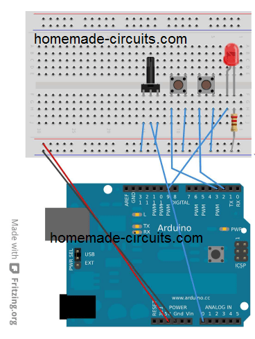
Connect the shown parameters with your Arduino as shown above.
A pot will have 3 terminals. The middle terminasl will connect with ANALOG IN 0 on the Arduino. The other two outer terminals may be connected to +5V and 0V supply rails.
Let's program and check out the results:
const int kPinPot = A0;

const int kPinLed = 9;

void setup()

{

pinMode(kPinPot, INPUT);

pinMode(kPinLed, OUTPUT);

}

void loop()

{

int ledBrightness;

int sensorValue = 0;

sensorValue = analogRead(kPinPot);

ledBrightness = map(sensorValue, 0, 1023, 0, 255);

analogWrite(kPinLed, ledBrightness);

}
You will find a couple of things which may look entirely new and not included in any of our earlier codes.
- The constant
kPinPotis assigned as A0, wherein A is the shortcut to describe one of the analogue pins. However A0 also refers to pin#14, A1 to pin#15 and so forth, and these allow you to be used as digital inputs/ouputs in case you run out of pins for an experiment. But remember you cannot use digital pins as analogue pins. - The line:
ledBrightness = map(sensorValue, 0, 1023, 0, 255);presents a new inside function in Arduino known as map(). This feature re-calibrates from a given range to another, termed as map(value, fromLow, fromHigh, toLow, toHigh). This may become crucial sinceanalogueReadgives out a value within the range of 0-1023, but analogWrite is able to accept a value from 0-255.
You may think, that since it is possible to control the brightness of an LED through a changing resistance, simply a pot could have been sufficient for the purpose, why the use of Arduino. Well, again it is just the foundation, to show how a pot could be configured with an Arduino.
No issues, now we'll do something which cannot be done without an Arduino.
In this experiment we will see how a pot's varying resistance could be used for controlling the blinking speed or rate of an LED.
Here's the program:
const int kPinPot = A0;

const int kPinLed = 9;

void setup()

{

pinMode(kPinLed, OUTPUT);

}

void loop()

{

int sensorValue;

sensorValue = analogRead(kPinPot);

digitalWrite(kPinLed, HIGH);

delay(sensorValue);

digitalWrite(kPinLed, LOW);

delay(sensorValue);

}
3.2.3 Avoiding delay()
The above code looks good, but the LED is unable check the pot value until it goes through each full cycle. For longer delays this process gets longer the user has to wait to see the pot response while he moves it. This delay can be avoided with some intelligent programming, so that it allows the user to check the value without minimum delays. Here's the code.
const int kPinPot = A0;

const int kPinLed = 9;

void setup()

{

pinMode(kPinLed, OUTPUT);

}

long lastTime = 0;

int ledValue = LOW;

void loop()

{

int sensorValue;

sensorValue = analogRead(kPinPot);

if(millis() > lastTime + sensorValue){

if(ledValue == LOW){

ledValue = HIGH;

}

else{

ledValue = LOW;

}

lastTime = millis();

digitalWrite(kPinLed, ledValue);

}

}
So what's that different in the above code? It is the following line which makes the difference.
long lastTime = 0;
Until this section, we have discussed about the variable int. However, there may be numerous more types variables that you may access. The list can e read below:
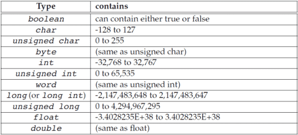
Presently, it may be only crucial to know that for storing relatively large numbers for the int variable, you could use the term long or a long int.
Here you can see another interesting function called millis().
This produces the time span in milliseconds the Arduino worked in its course of operation from the beginning (this will reset to 0 after every 50 days). Here it returns a long because if it returned int, counting for long periods may not be possible. Could you answer exactly how long? Answer is 32.767 seconds.
Therefore instead of using delay(), we check for millis(), and as soon as the particular number of milliseconds lapses we change the LED. Consequently we store the time we changed it last in lastTime variable, so that it allows us to check it again whenever desired.
3.3 RGB LEDs
So far we have played with a single color LED. Although LED color could be changed by replacing the LED with another color, but how about using RGB LEDs to change LED colors without changing the LEDs?
A RGB LED is basically an LED having a red, green, and blue LED embedded and merged into a single LED. It has one common lead which goes to the ground or 0V supply rail while the other 3 leads are fed with diversified PWM positive signals for implementing the intended color mixing.
You may wire the set up as shown below:
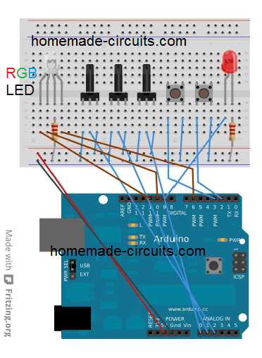
It may look a little complex, but actually it's a replica of our earlier LED control design using PWM.
Here's a practice program code:
const int kPinPot1 = A0;

const int kPinPot2 = A1;

const int kPinPot3 = A2;

const int kPinLed_R = 6;

const int kPinLed_G = 10;

const int kPinLed_B = 11;

void setup()

{

pinMode(kPinLed_R, OUTPUT);

pinMode(kPinLed_G, OUTPUT);

pinMode(kPinLed_B, OUTPUT);

}

void loop()

{

int potValue;

int ledValue;

potValue = analogRead(kPinPot1);

ledValue = map(potValue, 0, 1023, 0, 255);

analogWrite(kPinLed_R, ledValue);

potValue = analogRead(kPinPot2);

ledValue = map(potValue, 0, 1023, 0, 255);

analogWrite(kPinLed_G, ledValue);

potValue = analogRead(kPinPot3);

ledValue = map(potValue, 0, 1023, 0, 255);

analogWrite(kPinLed_B, ledValue);

}
After uploading this code, just see how the pot adjustments create interesting light effect on the RGB, it can be a real fun.
You will find that when all the 3 pots are moved maximum positions, instead of a white color you will see red. This is because red color is the most prominent among the 3 colors and therefore dominates in this situation. However you can experiment with the function map(), prior to executing it to the red portion of the LED, in order to create a more sensible balance.
Audio with Arduino
In this section we'll learn how to add basic sound and music to an Arduino setup.
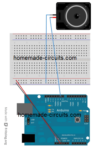
We will see how to switch a signal to a connected speaker with a desired frequency.
To be more precise, a middle A note will be tried, which is a 440 Hz frequency note.
To do this we'll simply play a middle A note, and optimize sine wave signal with square wave.
Also, we'll calculate the amount of time a loudspeaker may stay ON by suing the formula:
timeDelay = 1 second / 2 x toneFrequency.
timeDelay = 1 second / 2 x 440
timeDelay = 1136 microseconds
4.1 Let’s Hook up the Arduino Board
4.2 Adding a Simple note
We have already discussed about the function delay() where the unit is in milliseconds (second / 1000), however you will find yet another function delayMicroseconds() where the unit is in microseconds, (millisecond / 1000).
For the present setup we program a code to switch +5V ON/OFF on the selected pin linked with the speaker, at the rate of 440 pulses per second.
Recall, in the last discussion we determined the value 1136 microsecond for the intended audio note.
So here's the program for this, which will allow you to hear an audio note of 440 Hz as soon as you program the arduino with a speaker connected.
const int kPinSpeaker = 9;

const int k_timeDelay = 1136;

void setup()

{

pinMode(kPinSpeaker, OUTPUT);

}

void loop()

{

digitalWrite(kPinSpeaker, HIGH);

delayMicroseconds(k_timeDelay);

digitalWrite(kPinSpeaker, LOW);

delayMicroseconds(k_timeDelay);

}
With the above application it is possible to make an audio note, which also means we can create a music as per our own choice.
From the code we comprehend that Arduino includes a couple of integrated functions which additionally contributes to the creation of music.
The first one is tone() which works with 2 elements along with a 3rd optional element, designated as tone(pin, frequency, duration). or tone(pin, frequency)
Both are designated to execute respective of the time period assigned by you.
In the absence of a time period, the music will continue playing until the call tone() is executed again, or until you execute notone().
This will need to be done using a delay function in case music playing is the only fundamental thing you are implementing.
The time duration may be crucial since it allows providing a time for how long the music is played, so can you can free to do other things. As soon as the duration gets lapsed, the music stops.
The next function noTone() handles a single parameter and stops the selected tone on a particular assigned pin.
A peculiar warning: Anytime when tone() function is implemented, PWM function on pin 3 and 11 will stop operating.
Therefore whenever a speaker attachment is used in the program, make sure not to use the mentioned pin for the speakers, instead try some other pins for the speaker attachment.
OK so here's program for implementing music on a speaker, although it is not a real music rather a basis scale C note.
#define NOTE_C4 262

#define NOTE_D4 294

#define NOTE_E4 330

#define NOTE_F4 349

#define NOTE_G4 392

#define NOTE_A4 440

#define NOTE_B4 494

#define NOTE_C5 523

const int kPinSpeaker = 9;

void setup()

{

pinMode(kPinSpeaker, OUTPUT);

}

void loop()

{

tone(kPinSpeaker, NOTE_C4, 500);

delay(500);

tone(kPinSpeaker, NOTE_D4, 500);

delay(500);

tone(kPinSpeaker, NOTE_E4, 500);

delay(500);

tone(kPinSpeaker, NOTE_F4, 500);

delay(500);

tone(kPinSpeaker, NOTE_G4, 500);

delay(500);

tone(kPinSpeaker, NOTE_A4, 500);

delay(500);

tone(kPinSpeaker, NOTE_B4, 500);

delay(500);

tone(kPinSpeaker, NOTE_C5, 500);

delay(500);

noTone(kPinSpeaker);

delay(2000);

}
In the above code you may have noticed something new and that's #define.
This term works like a search and replace command for the computer while compiling is being done.
Whenever it finds the first thing before a space, it replace it with the remaining portion of the line (called macros).
So within this example when the computer sees NOTE_E4 it quickly replaces it with the quantity 330.
For more notes and customization you may refer to a file in your USB stick named pitches.h, where most of the frequencies could be found for your preference.
4.4 Music with functions
The code above looks good, but seems to have way many repetitions, there should be some method to shorten these repetitions, right?
So far we have worked with two essential functions included with Arduino. Now it may be time we created our own functions.
Each function must begin with the type of variable it may be associated with. For example the function void refers to type that returns nothing hence the name void. Note, we have already discussed a list of variable in our earlier sections, you may want to refer those.
Consequently, the particular function name gets an open parenthesis "(" followed by a list of comma separated parameters.
Each of the parameter acquires its type along with a name, and finally a close ")" parenthesis.
These parameters can be applied within the function in the form of variables.
Let's see an example below where we develop a function called ourTone() designed to merge the tone() with delay() lines, in a way that the function stops returning until the note has finished playing the tone.
We implement these functions in our previous code, and get the below program, see the last lines:
#define NOTE_C4 262

#define NOTE_D4 294

#define NOTE_E4 330

#define NOTE_F4 349

#define NOTE_G4 392

#define NOTE_A4 440

#define NOTE_B4 494

#define NOTE_C5 523

const int kPinSpeaker = 9;

void setup()

{

pinMode(kPinSpeaker, OUTPUT);

}

void loop()

{

tone(kPinSpeaker, NOTE_C4, 500);

delay(500);

tone(kPinSpeaker, NOTE_D4, 500);

delay(500);

tone(kPinSpeaker, NOTE_E4, 500);

delay(500);

tone(kPinSpeaker, NOTE_F4, 500);

delay(500);

tone(kPinSpeaker, NOTE_G4, 500);

delay(500);

tone(kPinSpeaker, NOTE_A4, 500);

delay(500);

tone(kPinSpeaker, NOTE_B4, 500);

delay(500);

tone(kPinSpeaker, NOTE_C5, 500);

delay(500);

noTone(kPinSpeaker);

delay(2000);

}

void ourTone(int freq, int duration)

{

tone(kPinSpeaker, freq, duration);

delay(duration);

}
Functions can be extremely handy to make a program easier to understand.
The following is an example where we are able to specify the choice of tone we want to play using two arrays. One array for retaining the notes, the other to retain the beats.
#include "pitches.h"

int kPinSpeaker = 9;

#define NUM_NOTES 15

const int notes[NUM_NOTES] = // a 0 represents a rest

{

NOTE_C4, NOTE_C4, NOTE_G4, NOTE_G4,

NOTE_A4, NOTE_A4, NOTE_G4, NOTE_F4,

NOTE_F4, NOTE_E4, NOTE_E4, NOTE_D4,

NOTE_D4, NOTE_C4, 0

};

const int beats[NUM_NOTES] = {

1, 1, 1, 1, 1, 1, 2, 1, 1, 1, 1, 1, 1, 2, 4 };

const int beat_length = 300;

void setup()

{

pinMode(kPinSpeaker, OUTPUT);

}

void loop()

{

for (int i = 0; i < NUM_NOTES; i++) {

if (notes[i] == 0) {

delay(beats[i] * beat_length); // rest

}

else {

ourTone(notes[i], beats[i] * beat_length);

}

// pause between notes

noTone(kPinSpeaker);

delay(beat_length / 2);

}

}

void ourTone(int freq, int duration)

{

tone(kPinSpeaker, freq, duration);

delay(duration);

}
You can clearly see on the first line the introduction of #include statement. The job of this statement is to pick up the entire file between the quotes and place it in the position of the #include statement. As per the standard rules these are strictly placed at the start of the program.
Chapter 5
Measuring Temperature
Just to recall, remember instead of writing large programs altogether, it is always wise to write and analyze small parts of codes, which helps in tracking down mistakes quickly.
5.1 Serial Monitor
Until now, the codes I will explained doesn't appear that easier to enable quick troubleshooting. Here we'll try to make things easier for monitoring and easier solving of a possible problem.
The Arduino has a feature which enables it to "talk back" with the computer. You may be observed that pin0 and pin1 are marked as RX an TX beside each other. These pins are actually tracked by a separate IC within Arduino which upgrades them to read across the USB cable while it's plugged to the PC.
The below section shows a full fledged program, please go though it, we'll learn regarding the new entries in the code thereafter. This code is same as expressed section 2.2 except the fact that it includes some extra data for allowing us to identify what it is been coded for.
const int kPinLed = 13;

void setup()

{

pinMode(kPinLed, OUTPUT);

Serial.begin(9600);

}

int delayTime = 1000;

void loop()

{

delayTime = delayTime - 100;

if(delayTime <= 0){ // If it would have been zero or less, reset it.

delayTime = 1000;

}

Serial.print("delayTime = ");

Serial.println(delayTime);

digitalWrite(kPinLed, HIGH);

delay(delayTime);

digitalWrite(kPinLed, LOW);

delay(delayTime);

}
You can identify two new things here, a new line in the setup() function.
Serial.begin(9600);
This line simply expresses the necessity of using the Serial1 code to enforce it with 9600 baud. (here serial refers to bits sent one after the other, and baud means the rate at which it is sent). This baud value and the one inside the serial monitor (we'll learn this later) must be equal, or else the data in serial monitor will show rubbish. 9600 being the standard becomes more convenient to use.
The second new entry are as follows
Serial.print("delayTime = ");

Serial.println(delayTime);
Here the second line suggests that the subsequent thing coming out from the serial port will start on the next line. That's how the second line is different from the fist line.
One more thing you can see are quotes ("). This is known as a string, which will used only like constants here, because further discussion on this topic can be too elaborate and beyond scope.
OK, we can now upload the above code in Arduino and see what happens.
What, oops nothing seems to have happened, the Arduino pin#13 LED blinked and stopped, while the Tx LED stayed blinking.
Well, that's because the Serial Monitor window is not fixed yet.
You need to click on the Serial Monitor box in your IDE as shown above. Don't forget to check the baud rate located at the bottom right, by default it should be 9600, and will match the code. If it is not make sure to select 9600.
The following video clip explains how it is done.
Now let's move ahead and learn how the above Serial Monitor feature can assist for processing the measurement of Temperature using Arduino
We'll use the IC TMP36 as the temperature sensor, having a range of -40 to 150 degrees Celsius.
The setup can be seen below:
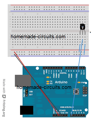
The following code will initiate the measurement of temperature by reading the output from the TMP36 sensor, and by sending them to the serial monitor of the ID.
const int kPinTemp = A0;

void setup()

{

Serial.begin(9600);

}

void loop()

{

float temperatureC = getTemperatureC();

Serial.print(temperatureC);

Serial.println(" degrees C");

// now convert to Fahrenheit

float temperatureF = convertToF(temperatureC);

Serial.print(temperatureF);

Serial.println(" degrees F");

delay(500);

}

float getTemperatureC()

{

int reading = analogRead(kPinTemp);

float voltage = (reading * 5.0) / 1024;

// convert from 10 mv per degree with 500mV offset

// to degrees ((voltage - 500mV) * 100)

return (voltage - 0.5) * 100;

}

float convertToF(float temperatureC)

{

return (temperatureC * 9.0 / 5.0) + 32.0;

}
So I will explain the code from the top.
float temperatureC = getTemperatureC();
Here you can see that we have included the variable type float.
This is the only variable type which features storing everything except integer numbers (numbers without decimal or fractional parts).
The accuracy from a float variable can be upto 6 to 7 digits.
The adjoining code getTemperatureC() is our own function which mathematically calculates and converts the sensed voltage difference from the TMP36 sensor into degrees Celsius.
float getTemperatureC()

{

int reading = analogRead(kPinTemp);

float voltage = (reading * 5.0) / 1024;

// convert from 10 mv per degree with 500mV offset

// to degrees ((voltage - 500mV) * 100)

return (voltage - 0.5) * 100;

}
In the next section of the codes, since the term analogIn() is assigned to return a figure between 1 to 1023, it becomes possible for us to assess the voltage from the sensor by multiplying our reading by 5 and then dividing it by 1024.
The sensor TMP36 is specified to generate a 0.5V at 0 degrees Celsius, and subsequently generates 10mV for every single rise in degree Celsius.
Here's the approximation that we are able to generate through the calculations:
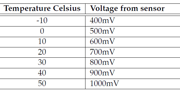
You can consider to be your first function which returns some value (note that all the remaining functions so far didn't return any value since they've been of the type void).
You can understand that in order to get a value from a function, you simply need to add return followed by the desired number you want to return.
When we say return it means the function returns a response or a reply whenever it is called, which could be applied to a variable.
When this is send to the Serial Monitor, the reading gets converted to Fahrenheit through convertToF().
float convertToF(float temperatureC)

{

return (temperatureC * 9.0 / 5.0) + 32.0;

}
This function picks up the Celsius range and converts it to Fahrenheit.
For converting Fahrenheit to Celsius we implement the formula Fahrenheit = 9/5 (Celsius)+ 32.
5.3 Interfacing an LCD
Now let's study how to interface or connect an LCD display with Arduino for getting visual display for the required outputs.
In our application we are going to employ an 84x48 graphical LCD, having an 84 pixel or dots horizontally, and 48 pixels vertical resolution. Since a dedicated controller becomes imperative for all LCDs, the present device also incorporates one in the form of PCD8544 controller.
In this tutorial we'll connect the above specified LCD module with Arduino, and apply certain routines to creates text messages on the display.
In the following figure you can find details regarding the interfacing of the LCD, along with a small 3.3V voltage regulator. This regulator is necessary since the LCD is specified to work with a 3.3V supply.
You can also see 8 pinouts from the LCD module, the pinout specifications can be studied from the following table:
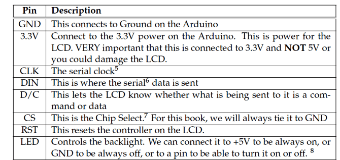
Now let's see how we can connect the LCD and the relevant parameters with our Arduino. The details can be visualized in the below shown illustration:
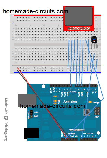
5.4 Communicating to the LCD
Although it is possible to write elaborate coeds for interacting with LCD from Arduino, we'll rather learn how to do the same using libraries.
Libraries comprise an assortment of codes that can be quickly applied for a selected Arduino program.
This enables the user to call a function effortlessly without having to go through complex coding work.
5.4.1 How Install the library
For this you will have to create a directory called libraries in your computer Arduino IDE, as explained here
5.4.2 Implementing the LCD Operations
Just as our previous approach, we'll first checkout the whole code and then try to understand the details of the individual lines.
#include <PCD8544.h>

const int kPin_CLK = 5;

const int kPin_DIN = 6;

const int kPin_DC = 7;

const int kPin_RESET = 8;

PCD8544 lcd(kPin_CLK, kPin_DIN, kPin_DC, kPin_RESET);

void setup()

{

lcd.init();

lcd.setCursor(0,0);

lcd.print("Hello, World!");

}

void loop()

{

lcd.setCursor(0,1);

lcd.print(millis());

}
The line includes the code #include <PCD8544.h>
The code #include instructs the PC to pickup the mentioned file and replace the #include element with the file contents during the course of compiling of the program.
The #include element can possess angle brackets which indicates searching in library directory, alternatively it may also possess quotes which indicates searching within the same directory the program is situated in.
The subsequent lines of code express the LCD pinouts, and then we write a new form of variable:
PCD8544 lcd(kPin_CLK, kPin_DIN, kPin_DC, kPin_RESET);
Here we are expressing a variable with the name lcd having the type PCD8544 and instructing the PC regrading its pinouts associated with the Arduino.
In this process we describe the variable to the PC by instructing how the pin clk, din, dc, and reset are interfaced with the Arduino.
void setup()

{

lcd.init();

lcd.setCursor(0,0);

lcd.print("Hello, World!");

}
The line lcd.init(); initializes the LCD operation. Once this is executed, the next line enforces a cursor to the upper left of the display. And the next subsequent line makes an effort to print the message "Hello, World".
This looks quite identical to the technique in which we sent messages over the serial monitor. The only difference being the use of the code lcd.print instead of serial.print.
The next block of code is actually called repetitively.
void loop()

{

lcd.setCursor(0,1);

lcd.print(millis());

}
Using this line lcd.setCursor(0,1); we fix the cursor to the 0th column at far left of the 1st row, over the LCD display.
The next line employs a shortcut: lcd.print(millis());
If you recall we have worked with millis() in our earlier codes, we could have applied the same here too through the codes:
long numMillis = millis();

lcd.print(numMillis);
However because of the fact that here no time periods in millisecond is involved, therefore we accomplish it by simply sending millis() function directly to lcd.print().
5.5 Combining the Whole Thing
OK, now let's combine all the codes I will explained above for making the LCD temperature circuit, and let's see how it looks:
#include <PCD8544.h>

const int kPin_CLK = 5;

const int kPin_DIN = 6;

const int kPin_DC = 7;

const int kPin_RESET = 8;

const int kPin_Temp = A0;

PCD8544 lcd(kPin_CLK, kPin_DIN, kPin_DC, kPin_RESET);

void setup()

{

lcd.init();

lcd.setCursor(10,0);

lcd.print("Temperature:");

}

void loop()

{

float temperatureC = getTemperatureC();

// now convert to Fahrenheit

float temperatureF = convertToF(temperatureC);

lcd.setCursor(21,1);

lcd.print(temperatureC);

lcd.print(" C");

lcd.setCursor(21,2);

lcd.print(temperatureF);

lcd.print(" F");

delay(100);

}

float getTemperatureC()

{

int reading = analogRead(kPin_Temp);

float voltage = (reading * 5.0) / 1024;

// convert from 10 mv per degree with 500mV offset

// to degrees ((voltage - 500mV) * 100)

return (voltage - 0.5) * 100;

}

float convertToF(float temperatureC)

{

return (temperatureC * 9.0 / 5.0) + 32.0;

}
Everything looks standard in the above program, except the use of the function setCursor(). This is employed to align the text as far as possible around the center of the display.
Great! And congrats, you have just programmed your own little LCD temperature indicator using Arduino.
Practical Arduino Applications
Since, at this point we have comprehensively covered the various programming techniques in detail, it's time to etst them through by applying them for a few useful practical implementations.
We'll begin with sensors and see how sensor devices could be used with Arduino by executing a few sample codes.
7.1 Introduction to Sensors
In this tutorial I will explain regarding the wide variety of sensors that could be used with Arduino. These may include devices like light sensor LDR, magnetic hall effect sensor, tilt sensors, vibration sensor, pressure sensor etc.
We'll begin with the interfacing of light sensor LDR with Arduino, as shown i the following diagram:
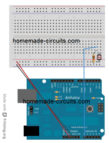
As we all know, LDR is a light dependent resistor device whose resistance depends on the intensity of the ambient incident on its surface.
The intensity of light is inversely proportional to the resistance reading of the LDR.
Here I will explain how this property can be integrated with Arduino for executing an useful application:
The complete program code can be visualized as given below:
const int kPin_Photocell = A0;

void setup()

{

Serial.begin(9600);

}

void loop()

{

int value = analogRead(kPin_Photocell);

Serial.print("Analog Reading = ");

Serial.print(value);

if(value < 200){

Serial.println(" - Dark");

}else if(value < 400){

Serial.println(" - Dim");

}

else if(value < 600){

Serial.println(" - Light");

}

else if(value < 800){

Serial.println(" - Bright");

}

else{

Serial.println(" - Very Bright");

}

delay(1000);

}
All the parameters used in the code have been already discussed in our course which we have learned so far. You can check the lines by referring to the relevant sections.
The values were chosen randomly, you can easily change as per your own preferences.
Tilt Sensor
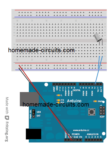
A tilt sensor is a simple device which can be used to detect a tilt action on any object where it is installed. The device basically has a metallic ball inside, which on tilting rolls over a pair of contacts causing a conduction across those contacts. These contacts being terminated as the leads of the tilt switch, is used with a an external circuit for detecting the conduction due to a tilting action and activating the desired output application.
Now let's see how a tilt sensor device could be wired up. The image below gives us an idea regarding the complete configuration:
const int kPin_Tilt = 3;

const int kPin_LED = 13;

void setup()

{

pinMode(kPin_Tilt, INPUT);

digitalWrite(kPin_Tilt, HIGH); // turn on built-in pull-up resistor

pinMode(kPin_LED, OUTPUT);

}

void loop()

{

if(digitalRead(kPin_Tilt) == HIGH){

digitalWrite(kPin_LED, LOW);

}

else{

digitalWrite(kPin_LED, HIGH);

}

}
In this example the default pin#13 LED is used as the tilt indicator.
You can clearly see the inclusion of the pull-up resistor here, quite similar what we did in section 3.1. Therefore the term LOW indicates that the tilt function is not triggered.
7.4 Reed Switch Relay (Miniature Magnet Activated Relay)
Now let's see how to hook up a relay switch or a magnetic field sensor with Arduino. A reed relay is a kind of switch which activates or conducts when a magnetic field or a magnet is brought near it. Basically it has a pair of ferromagnetic contacts inside a miniature glass enclosure which join or make contact due to magnetic pull whenever a magnetic is at a close proximity to it. When this happens the terminals of the contacts show conduction due to closing of the contacts.
Here too we use the pin#13 LED for indicating the response. You may connect an external LED from this pin if required as per our earlier explanations.
const int kPinReedSwitch = 2;

const int kPinLed = 13;

void setup()

pinMode(kPinReedSwitch, INPUT);

digitalWrite(kPinReedSwitch, HIGH); // turn on pullup resistor

pinMode(kPinLed, OUTPUT);

}

void loop()

{

if(digitalRead(kPinReedSwitch) == LOW){

digitalWrite(kPinLed, HIGH);

}

else{

digitalWrite(kPinLed, LOW);

}

}
The code terms should be familiar and self explanatory.
7.5 Vibration sensor using Piezo Transducer
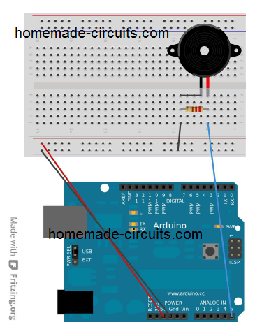
In the next sample program we'll see how a piezo transducer may be used as a vibration sensor to illuminate an LED through Arduino.
A piezo element actually is a device which generates vibration or oscillation when an frequency is applied across its terminals. However the same piezo could be used in the reverse process for generating electrical pulses in response to vibration applied on its body. This vibration could be in the form of a knock or hit on the surface of the piezo.
Setup the Arduino and a piezo element as given in the following figure
const int kPinSensor = A5;

const int kPinLed = 13;

const int k_threshold = 100;

int ledState = LOW; // variable used to store the last LED status, to toggle the light

void setup()

{

pinMode(kPinLed, OUTPUT); // declare the ledPin as as OUTPUT

}

void loop()

{

int val = analogRead(kPinSensor);

if (val >= k_threshold) {

ledState = !ledState; // toggle the value of ledState

digitalWrite(kPinLed, ledState);

delay(20); // for debouncing

}

}
The threshold 100 is introduced just to make sure that the Arduino responds only to the genuine vibrations through knocks, and not other smaller vibrations such as from loud sounds, or horns.
The selection of A5 pin is not mandatory, you can select any other analogue inputs as per your preference and by matching it in the program code.
Using Servo Motor with Arduino
A servo motor is a type of DC motor which can be rotated to precise angles as per the demand of a particular application. It can be done by applying a calculated command to the relevant inputs of the motor to produce an accurate rotational or turning angle within 180 degrees range on the motor.
Typically a servo motor has 3 wires or inputs. The positive wires is normally red in color, the negative or ground wire is black, which the command wire or the signalling wire is normally white or yellow in color.
Arduino facilitates servo motor control through built in support language which makes controlling very convenient and ideal for servo motors.
The following example will show us the basic setup program for implementing servo motor control through Arduino:
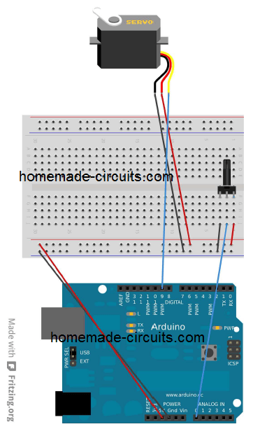
The code is given below:
#include <Servo.h>

Servo servo1;

const int kPinPot = A0;

const int kPinServo1 = 9;

void setup()

{

servo1.attach(kPinServo1);

}

void loop()

{

int val = analogRead(kPinPot);

val = map(val, 0, 1023, 0, 180);

servo1.write(val);

delay(15);

}
We can see a couple of new entries here. One that tells the attached wire of the servo to what pin it is assigned. The other one is the code which provides the pin a value between 0 and 180, for determining the angle of rotation on the servo.
Conclusion
The Arduino subject can be infinitely long, and therefore beyond the scope of this article. However, I hope the above tutorial should have certainly helped you to learn the very basics of Arduino, and understand important parameters through the various example application codes.
Hopefully more information may be updated from time to time here, whenever it is available.
In the meantime enjoy your programming course, Happy Arduinoing to you!!