The following concept I have explained a simple yet viable solar grid tie inverter circuit which can be modified appropriately for generating wattage from 100 to 1000 VA and above.
What's a grid tie inverter
It's an inverter system designed to work just like an ordinary inverter using a DC input power with an exception that the output is fed back to the utility grid.
This added power to the grid may be intended for contributing to the ever increasing power demands and also for generating a passive income from the utility company in accordance with their terms (applicable in limited countries only).
For implementing the above process, it's ensured that the output from the inverter is perfectly synchronized with grid power in terms of RMS, waveform, frequency and polarity, for preventing unnatural behavior and issues.
The proposed concept designed by me, is yet another grid tie inverter circuit (not verified) which is even simpler and reasonable than the previous design.
The circuit may be understood with the help of the following points:
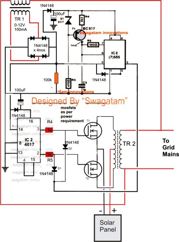
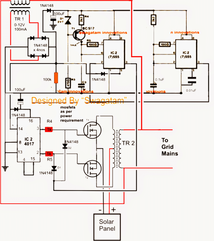
How the GTI Circuit Works
AC mains from the grid system is applied to TR1 which is a stepped down transformer.
TR1 drops the mains input to 12V and rectifies it with the help of the bridge network formed by the four 1N4148 diodes.
The rectified voltage is used for powering the ICs via the individual 1N4148 diodes connected across the relevant pinouts of the ICs, while the associated 100uF capacitors make sure that the voltage is appropriately filtered.
The rectified voltage acquired just after the bridge is also used as the processing inputs for the two ICs.
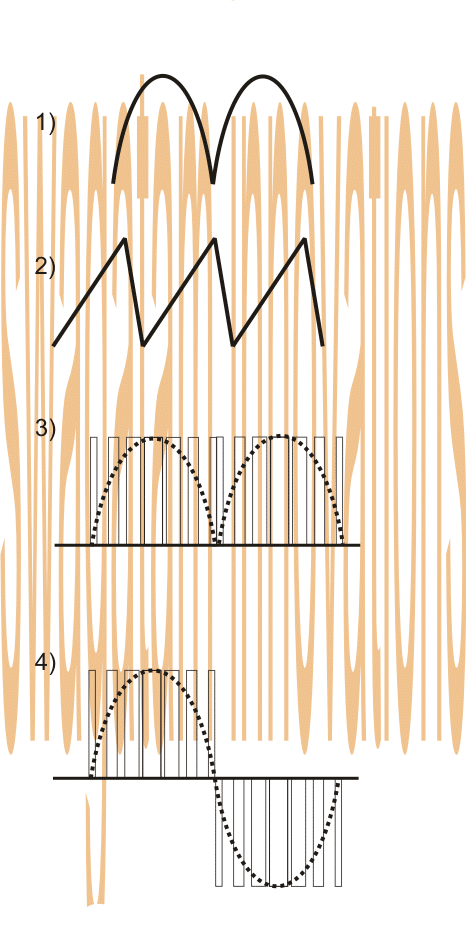
Since the above signal (see the waveform image #1) is unfiltered it consists of a frequency of 100Hz and becomes the sample signal for processing and enabling the required synchronization.
First it's fed to pin#2 of IC555 where it's frequency is used for comparing with the sawtooth waves (see waveform #2) across pin#6/7 obtained from the collector of the transistor BC557.
The above comparison enables the IC to create the intended PWM output in sync with the frequency of the grid mains.
The signal from the bridge is also fed to pin#5 which fixes the RMS value of the output PWM precisely matching with the grid waveform (see waveform #3).
However at this point the output from the 555 is a low in power and needs to be boosted and also processed such that it replicates and generates both the halves of the AC signal.
For executing the above, the 4017 and the mosfet stage is incorporated.
The 100Hz/120Hz from the bridge is also received by the 4017 at its pin#14 which means now it's output would sequence and repeat from pin#3 back to pin#3 such that the mosfets are switched in tandem and exactly at the frequency of 50Hz, meaning each mosfet would conduct 50 times per second, alternately.
The mosfets respond to the above actions from the IC4017 and generate the corresponding push pull effect over the connected transformer which in turn produces the required AC mains voltage at its secondary winding.
This may be implemented by supplying a DC input to the mosftes from a renewable source or a battery.
However the above voltage would be an ordinary square wave, not corresponding to the grid waveform, until and unless we include the network comprising the two 1N4148 diodes connected across the gates of the mosfets and pin#3 of IC555.
The above network chops the square waves at the gates of the mosftes accurately with respect to the PWM pattern or in other words it carves the square waves exactly matching the grid AC waveform, albeit in PWM form (see waveform #4).
The above output now is fed back to the grid conforming the grid specs and patterns accurately.
The power output can be altered right from 100 watts to 1000 watts or even more by appropriately dimensioning the input DC, the mosfets and the transformer ratings.
The discussed solar grid tie inverter circuit remains operative only so long as the grid power is present, the moment utility mains fails, TR1 switches OFF the input signals and the entire circuit comes to a halt, a situation that's strictly imperative for grid-tie inverter circuit systems.
Warning: The author cannot be held responsible for the results of the experiment. Please do it at your own risk!! The projects explained here are recommended only for the experts in the field of electronics.
Circuit Diagram
Assumed Waveform Images
Something's not right in the above design
According to Mr. Selim Yavuz the above design had a few things which looked doubtful and needed correction, let's hear what he had to say:
Hi Swag,
hope you're well.
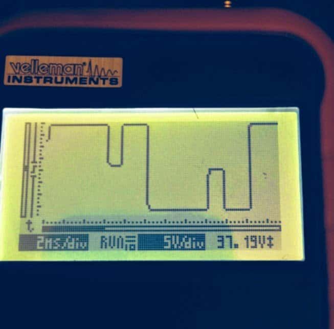
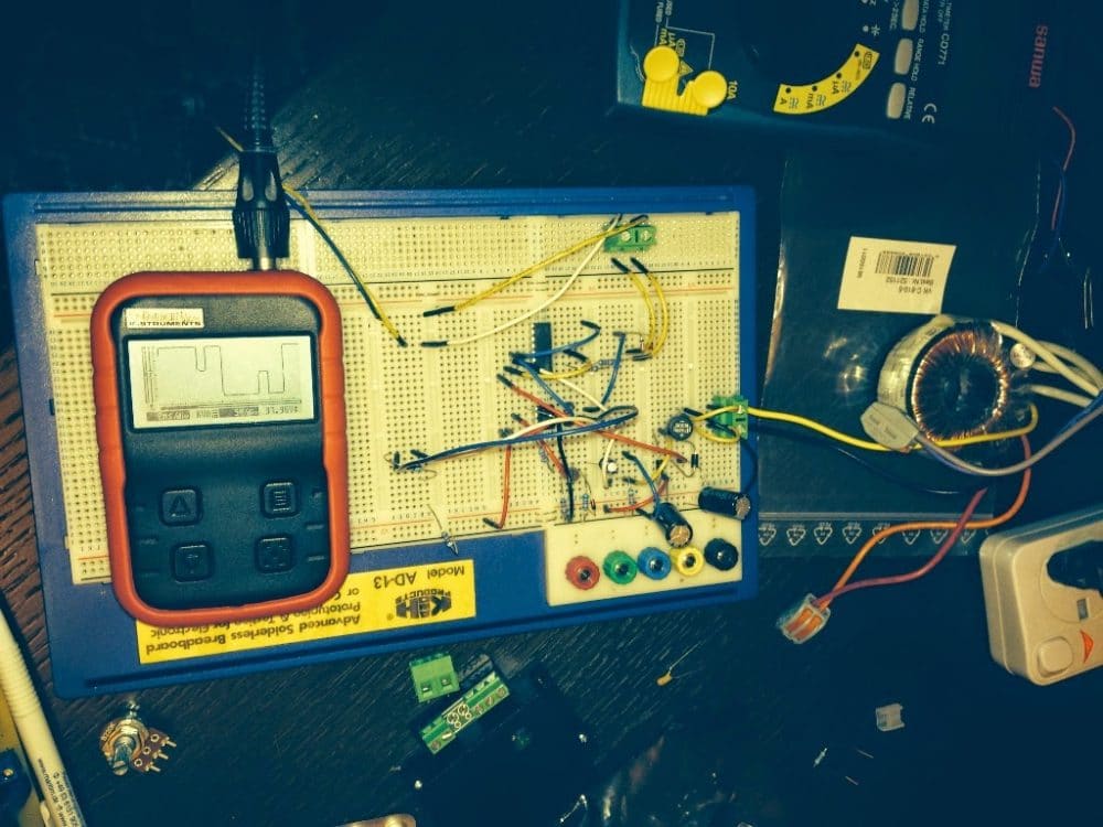
I tried your circuit on a bread board. It seems to work except pwm part. For some reason, I get a double hump but no real pwm. Could you please help me understand how 555 does pwm? I noticed that 2.2k and 1u create a ramp of 10ms. I believe the ramp should be much faster than that as the half wave is 10ms. May be I missed a few things.
Also, 4017 does a clean job switching happily back and forth. When you power up, the 100 hz clock makes the counter always start from 0. How can we assure that it always in phase with the grid?
Appreciate your help and ideas.
Regards,
Selim
Solving the Circuit Issue
Hi Selim,
Thanks for the update.
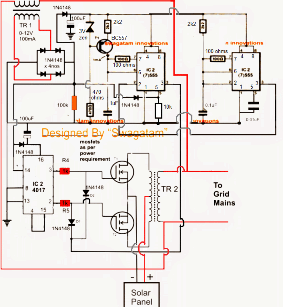
You are absolutely correct, the triangle waves should be much higher in frequency compared to the modulation input at pin#5.
For this we could go for a separate 300Hz (approximately) 555 IC astable for feeding pin2 of the pwm IC 555.
This will solve all the issues according to me.
The 4017 should be clocked via 100Hz received from bridge rectifier and its pin3, pin2 should be used for driving the gates and pin4 connected to pin15. This will ensure perfect synchronization with the mains frequency.
Regards.
Finalized Design as per the above conversation
The above diagram has been redrawn below with distinct part numbers and jumper notations
WARNING: THE IDEA IS BASED SOLELY ON IMAGINATIVE SIMULATION, VIEWER DISCRETION IS STRICTLY ADVISED.
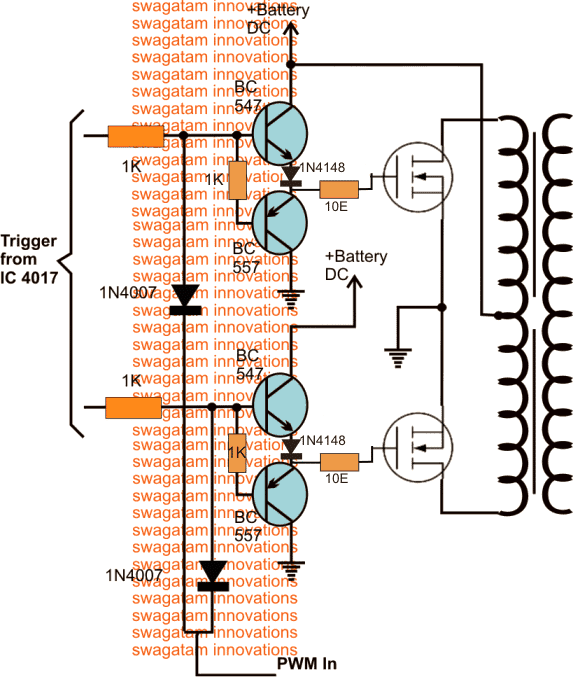
A major issue with the above design faced by many of the constructors was the heating up of one of the mosfets during the GTI operations. A possible cause and remedy as suggested by Mr. Hsen is presented below.
The proposed correction in the mosfet stage as recommended by Mr. Hsen is also enclosed here under, hopefully the said modifications will help control the issue permanently:
Hello mr. Swagatam:
I watched again your diagram and I am firmly convinced that the gates of the MOSFETs will reach a modulating signal (HF PWM) and not a simple signal 50 cs. Therefore I insist, a more powerful driver the CD4017 must be incorporated, and the series resistance should be of a much lower value.
Another thing to consider is that at the junction of the resistor and the gate should not be another added element, and in this case I see going to the diodes 555.
Because this may be the reason why one of the heats MOFETs because it can self oscillate. So I think that the mosfet heats because it is oscillating and not because of the output transformer.
Excuse me, but my concern is that your project succeed because I feel very good and it is not my intention to criticize.
Yours affectionately, hsen
Improved Mosfet Driver
As per the suggestions from Mr Hsen, the following BJT buffer could be employed for ensuring that the mosfets are able to work with better safety and control.
Ideally it is strictly recommended to calculate all the parameters before designing a proper Grid Tie inverter. Below explained are the key formulas and calculations pertaining to grid-tie inverters which includes power, voltage, and efficiency parameters:
Power Flow in Grid-Tie Inverters
Grid-tie inverters are designed to inject power into the grid while maintaining grid synchronization. The key relationship for power flow can be given as:
- Pin = Pout + Ploss
Where:
- Pin = Input power from the DC source (like a solar panel)
- Pout = Output power injected into the grid
- Ploss = Power losses in the inverter (maybe due to switching, conduction, and transformer losses)
Inverter Efficiency
The efficiency of a grid-tie inverter could be defined as:
- Efficiency (%) = (Pout / Pin) × 100
Where:
- Pout = AC power output to the grid
- Pin = DC power input from the source
You can normally assume grid-tie inverters to have have efficiencies between 90%–98%.
Power Factor (PF)
Grid-tie inverters normally needs to operate at a high power factor to ensure efficient power transfer to the grid. The power factor can be calculated as:
- PF = Pout / (Vrms × Irms)
Where:
- Pout = Real power output (W)
- Vrms = RMS grid voltage (V)
- Irms = RMS current injected into the grid (A)
Ideally for any grid-tie inverter you must try to get a PF ≈ 1 (purely resistive load).
Maximum Power Point Tracking (MPPT)
Grid-tie inverters configured with MPPT can adjust the input voltage to maximize power extraction from the source. The key equation for calculating maximum power can be calculated using the formula:
- Pmax = Vmp × Imp
Where:
- Pmax = Maximum power output of the DC source (W)
- Vmp = Voltage at maximum power point (V)
- Imp = Current at maximum power point (A)
Sizing the Inverter
Always make sure the inverter is rated to handle the peak power of the DC source. For a solar panel integration, you can use the following formula:
- Pinv = Parray / ηinverter
Where:
- Pinv = Rated power of the inverter (W)
- Parray = Total power of the solar array (W)
- ηinverter = Efficiency of the inverter (decimal)
Lets solve an Example Grid tie Problem as given below:
Consider we have an solar panel array rated at 5 kW and the inverter efficiency is 95% then the inverter should have a rating of:
Pinv = 5000 / 0.95 ≈ 5263W
RMS Voltage and Current
The RMS values of voltage and current injected into the grid can be calculated as:
- Vrms = Vpeak / √2
- Irms = Ipeak / √2
Where:
- Vpeak = Peak voltage of the AC waveform (V)
- Ipeak = Peak current of the AC waveform (A)
Synchronization with the Grid AC Line
We have to ensure that the inverter must match the grid's voltage, frequency, and phase to inject power. The key relationship is given by the formula:
- Grid Frequency = Inverter Frequency
Total Harmonic Distortion (THD)
The inverter must be designed to minimize the harmonic distortion in the current injected into the grid. This THD can be calculated as:
- THD (%) = (√(I22 + I32 + ... + In2) / I1) × 100
Where:
- I1 = Fundamental frequency current
- I2, I3, ..., In = Harmonic currents
In order to comply with the terms of the grid supply network, make sure the THD is typically less than 5%.
DC Link Capacitor Sizing
In grid-tie inverters we use the DC link capacitor to smooth the input DC voltage. Its value can be estimated as:
- Cdc = Iload / (4 × f × ΔVdc)
Where:
- Cdc = DC link capacitance (F)
- Iload = Load current (A)
- f = AC grid frequency (Hz)
- ΔVdc = Allowed ripple in DC link voltage (V)
Transformer Turns Ratio
If you are using a transformer in your grid-tie inverter for isolation then the turns ratio can be calculated as:
- N = Vgrid / Vdc
Where:
- N = Turns ratio
- Vgrid = RMS grid voltage (e.g., 230V or 120V)
- Vdc = DC input voltage
Reactive Power (Q)
Your inverters can inject reactive power in the grid so if required you can calculate it as:
- Q = Vrms × Irms × sin(θ)
Where:
- θ = Phase angle between voltage and current
Grid Current Calculation
The current injected into the grid can be calculated using Ohms law as:
- Igrid = Pout / Vrms
Example Calculations
Example 1: Efficiency Calculation
- Input power (Pin): 5000W
- Output power (Pout): 4800W
Efficiency = (Pout / Pin) × 100
= (4800 / 5000) × 100 = 96%
Example 2: RMS Current
- Pout = 4800W
- Vrms = 230V
Irms = Pout / Vrms
= 4800 / 230 ≈ 20.87A

Questions & Answers
I wonder if this scheme is functional , because I need grid tie to work 100W .
It is an experimental setup, you will need to test it on a small scale and verify whether it suits your application or not…
Sir please upload a circuit diagram of 3kw grid tie inverter circuit diagram for all viewers, please Sir…..
Thanks Saroj, let me try it, I will update you if it is feasible for me…
sello,
Got a question and a suggestion: on increasing the frequency of the 2 / 555s your using -= why not kidk them up to the 50 kHz frequency you specify in your 5kVA inverter — it will follow the grid input frequency – just chopped up more – for a better sinewave.
The suggestion is swapping out the BC547 drivers for Microchip TC4420 6 Amp drivers fro my IRF 740 MOSFETs I’ve used for years,
Hope you get back to me on the frequency question.
Hi, thanks for your interesting question and a good suggestion.
If the frequency is increased then the transformer will need to be a ferrite core based transformer, an iron core won’t work.
Sure, any good MOSFET driver as suggested by you can be used for enhancing the MOSFET switching.
The idea that I’m waiting for.
For safety reason and research purpose, I will utilize a small transformer to mimic the grid.
It will sync in a low voltage environment, about 12Vac. Even a 3 phase grid is also safe.
Best Regards
Dear Sir,
On GRID TIE INVERTER, Should I use IGBT as a final full-bridges? cause i have burned a lot of mosfet on it.
Thanks in advance
Hello Tamcat, if you build and check the stages step-wise with an oscilloscope then the mosfets will not burn. You must try with mosfets only initially, but only after understanding all the stages step wise
hello i really like to test the inverter circuit designed by you but wonder if the tr2 transformer is ferrite excluding the loops of the wire according to the above diagram, what frequency should be taken
TR2 can be a iron core transformer, so the frequency of the PWM can be set to around 200 Hz.
Sir, soon I’m going to experiment above circuits.
Pls suggest if have anybody workouts.
I’m a solar hobyest enterprising from rural India.
I have selective apx.60 projects to expt. pl contact me to know the coponent sources etc.
Hello Rajeso, I have designed these circuit with my knowledge and research, I have not yet tested it practically.
Which part of this cct ensures the phase of solar fed in is same as grid phase?
The IC2 pin5 stage. It gets the sine wave amplitude information from the bridge rectifier and chops the output waveform with equivalent PWM so that the inverter AC output is exactly equivalent to the existing grid mains AC
Hello sir. I’m Abel and I enjoy visiting your blog and exploring the projects you post. I have a problem of my own though. I’ve just bought 4 X 330 watt solar panels. I need to run a fridge directly from the solar panels without using batteries. The total series voltage I get is 140 volts. Can you please help me with a circuit to achieve this. Thank you very much sir.
Thank you Abel for liking my posts and visiting this site! Can you please provide the voltage and wattage specifications of the fridge, is 220V rated or 110V? I’ll try to provide yo with an appropriate solution , once I know these specs.
Hello Swagatam, my doubt is that the output phase of the inverter is the same as the network. And you would not have to have a transformer with voltage higher than the mains.
Anyway I think I can use the circuit outside the network using only the sinusoidal reference, to have a pure output.
I liked your project, thank you.
Thank you Carlos, I might have mentioned it due to fact that the lower RMS of the SPWM from the IC 555 might reduce the output voltage. However now I realize that this can be adjusted by having the primary voltage of the transformer exactly matching the RMS of the SPWM. The secondary side can be a 220V or 120V it does not need to be changed.
thanks for your work! I appreciate the effort and time that goes into making this website. the transformers for larger systems are quite costly, what do you think of the research paper regarding transformerless grid tie inverters? would it be viable to make a 5kw transformerless grid tie inverter using the following experimental designs?
https://umexpert.um.edu.my/file/publication/00005361_105654.pdf
It looks great! You can definitely use it to make a 5kva inverter.
Hi sir
How we create resitor and capcitor round 1khz frequency as our inverter requirement?
Good day sir..
Can you give me the link of clear and efficiant grid tie inverter for proteous simulation
Hi Rizwan, sorry I do not have any other design other than the above ones.
sir gud day..can I ask what is that D1 is it zener 2.7v? and sir do you have clearer schematic diagram of this ck5…and please if you have kindly send it to my email….thank you so much sir…I’m you avid follower….
Good day Sinoda, D1 is a 2.7V zener diode, but you can use any zener below 4.7V.
I’ll soon make the design clearer and update it for you in the article.
I appreciate your interest and I am Happy to help!
hi sir…good day and more power to you….I just want to ask if this ckt was already tested and running…becoz I want to build this also..thank you sir…
Hi Sinoda, it is not tested by me yet, but other readers have tested it successfully.
What will be the proposed cost of construction?
Anything between $100 to $500 depending on the wattage.
sir
first i tried this circuit on Proteus software then i moved toward hardware circuit. i am facing problems in making hard, sir On TR2 transformer 113V are appearing yet i didn’t connect with TR1,
i am using 12V, 5Ah battery
if AC mains turns off then no output appear on transformer , mean only with DC supply transformer gives no output,,,, sir Kindly tell me reason of this how can i resolve this
and one more problem is that the transformer 6-0-6 and IC556 i used in the circuit get heat up instantly , tell me reason of the heating of IC and transformer , how can i resolve this problem
Rida, this project is a significantly complex project and therefore it will need to be implemented stepwise or stagewise, very carefully. First you must build a normal inverter circuit using the three IC 555s, and a single IC 4017 and try to get 220V output from the transformer…once this is confirmed after that you can proceed with the grid transformer integration, and further on.
Please let me know if you face any problems…
Hi swag…
I tried your circuit of grid tie inverter I don’t understand the connection of ic 555 pin no3 which is output pin but why it is connect with a cathode side of diode….
Hi Mayur, the pin#3 produces positive and negative outputs alternately while oscillating, we only want the negative output to act on the gates of the mosfets, so that during the negative outputs the mosfets get switched OFF, here the positive outputs are not relevant, because the positives is already coming from the IC 4017 pins, we only need the negatives from the IC 555 to react on the gates for creating the chopping effect.
That is why the diodes are introduced in the reverse biased condition.
Hi SWAGATAM i am working on this GTI and i am using 25A battery can tell me what should be the rating of TR2. if you will tell it will resolve my problem
thanks in advance
Hi Mega, TR2 voltage rating should be slightly lower than the battery voltage and the current 5 times less than the battery AH
Hi Guys,
I am also trying to design Grid-Tie Inverter and reached this article by googling. I need to ask if any of you finally got a successful working inverter?
If yes can you guys please share the details of the working design?
It would help me to prevent reinveting the weel
Regards,
Faisal
Hi
Any update on this design? please do a final design and parts.
any update on this design? please post the final layout with parts and any comment if already tested?
the inverter is for solar would it work for a wind turbine
no it won't work for wind turbines
Thank you, have only recently become interested in the GTI, for me it was very interesting and timely
you are welcome!
Possible person benefit me how what kind of plug which is based
I am very interested in your article, I place a lot of problems like this. I want to learn a lot from your article.
I've seen articles that you provide. I want to ask, the battery was connected to the mosfet leg or TR? and, in the synchronizing voltage must be the same system, the inverter output will be the same whether the system? if not then there will be the potential difference and the GTI will be load system.
thanks Agung, the inverter is perfectly synchronized with the grid, I have tried to take care of this issue as far as possible.
The voltage may be tweaked at the start before the integration with the grid by adjusting the preset at pin5 of the first 555 IC.
Once this is adjusted to the level of the grid, the output could be joined with the grid and rest will be automatically monitored and adjusted by the circuit itself, hopefully.