In this post I have explained a simple method of automatically switching ON an inverter fan whenever the unit is operating in the charging mode or inverter mode, in order to ensure optimum cooling of the internal power devices. The idea was requested by Mr. Sudip Bepary.
Circuit Objectives and Requirements
- I have just bought a new sine wave ups card (850va) (pic16f72)... It's working good.But, this board does not have cooling fan terminal.
- My transformer and Mosfet is getting hot at the condition of inverting and charging.
- So, please respond me with proper guide to connect DC cooling in this board to which the fan can on at time of charging and inverting.
- Please, please, please help me from this problem.
The Design
The requested idea for an automatic inverter fan switch ON circuit while the inverter is in the inverting mode or charging mode can be implemented using the following explained concept:
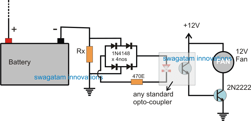
As can be seen in the figure, the negative of the battery is connected with a series Rx resistor such that any current whether from the charger or from the inverter passes through this resistor during the irrespective operations.
This implies that during any of the operations the resistor Rx is able to generate a proportionate amount of potential drop across itself enabling the connected sensing circuit to respond to this developed voltage.
A bridge rectifier can also be seen connected across Rx to ensure that it always produces a single polarity voltage regardless of the polarity of the current that may be passing through Rx.
For example while charging the battery the current polarity could be the opposite compared to the inverting mode polarity, however the bridge rectifier corrects both the possibilities and offers a single polarity output for the next stage which is an opto coupler stage.
The optocoupler LED lights up whenever the battery is operated by some method and this is instantly converted into a triggering voltage for the BJT 2N2222 associated with the optocoupler transistor.
The 2N2222 along with the opto transistor is configured in a Darlington mode to ensure a high gain for the BJT pairs which in turn makes sure that the Rx value can be selected to be as small as possible, thereby allowing minimum resistance for the inverter operations.
As soon as the 2N2222 conducts it turn ON the connected fan which begins cooling the vital devices of the inverter and makes sure that they are never hot and vulnerable during the charging process or while the inverter is in the inverting mode.
Calculating the Current Limiter Resistor
The Rx value may be selected with some trial and error. The LED could be expected to illuminate just slightly at around 0.7V, therefore the formula for calculating Rx can be expressed as
R = V/I = 0.7/I
I (current0) could be selected to be 50% of the calculated charging current, since at this current the power devices could be expected to be just getting warm.
Let's assume if the charging current is 10 amps, then the formula could be handled in the following manner
R = 0.7/5 = 0.14 ohms
Similarly other proportionate values of Rx could be calculated for successfully initiating the proposed automatic inverter fan switch ON during charging and inverting mode of the unit.

Questions & Answers
Hello, Mr. Swagatam, thank you for your prompt reply. I think that’s a good idea.
Hi Carlos, I think the following circuit can be tried:
https://www.homemade-circuits.com/make-simplest-temperature-indicator/
The diode will need to be kept in normal atmospheric temperature while the BC547 as the temperature detector…
Hello good afternoon Mr. Swagatam, this time I want to ask you if you have any circuitry to detect when the color/ fan It stops either when it runs slower due to dirt or also when it doesn’t start, since I have to use forced cooling for a board with 4 igbt.. Thank you very much for your time
Hi Carlos, Good afternoon, I think the easiest method would be to detect a temperature change. If, after switching on the fan, the temperature does not drop to the expected level, that would indicate malfunctioning fan and turn on a buzzer or an LED…what do you think?
I have a 50 hz standard sinusoidal ups out, how can I output 60 hz? I need help unloading.
fan is running after chainged the transister BC 548 B WHEN BATTERY Connected . what will be reasion,
sir next how to solve the problem
What value did you select for RX?
Hello swagatam
in the above circuit by you the resistance ‘Rx’ will continuously consume some power which is not acceptable.
J K barik
Hello JK, without a sensing resistor it may be impossible to detect current, so current sensing through a resistor is the only viable option. By the way the current loss across the resistance is hardly anything therefore is quite acceptable.
Hello Swagatam
I have bypassed inverter LOAD Sensor to run my fridge which was tripping at OVER LOAD. Now it works fine but I doubt if the fan will work. I think if there is sufficient LOAD ( say 50%) then i
micro controller will give signal to run the fan. Am I right? Let us see what to do. If so then I will but separate temp controlled mini circuit. Any idea?
thanks in Advance
J K barik
Hello JK, It will be difficult to suggest any ideas since I do not know how your inverter circuit is configured to work.
will the inverter UPS stops working if the Fan does not work ?
No, for that you may have to employ a thermal shutdown circuit
It is a great idea being here
Hi sir, I really appreciate you good Job here God bless you, please sir I need a high and low voltage cutoff circuit for my 24v inverter system.
Thanks Casmir, is it for 24V battery or 220V grid voltage
It is for 24v battery sir
You can try the second circuit from this article. Use a 24V relay and a 0-24V transformer.
https://www.homemade-circuits.com/opamp-low-high-battery-charger/
Good day,
I want to use some fets as a switch but I only want to pass +5v through the fet.
Ill be using the arduino to do analog wirte to the pwm pins but i need a stable voltage from each pin, so I wanted to send a pwm signal from the arduino pins to the gate of some fets and and send a 5v from a power supply to the drain of each fet and then use the source of the fet to pass the switch +5v to the device, is anything wrong with that concept?
It is possible but not by applying 5V to the FET gates from Arduino directly. Instead you can use buffer gates between the Arduino pins and the fet gates. This buffer IC must be operated with 12V so that the output to the fet gates are also 12V.
The buffer IC could be a CD4010B
Good day, God bles u for your generosity for the whole world. I am new in inverter building. My problem is the charging. I want to build charger for 12v 200w battery. I also dont know how to connect relay. Pls, can you give me charger circuit for 12v 200w battery and explain to me how to connect relay? Thanks and God bless.
Hello Yusuf, you can try the second circuit from this article
https://www.homemade-circuits.com/make-this-48v-automatic-battery-charger/
since your battery is a 2V you will need a few modifications in the design, which are as follows:
remove all the 22K resistors and replace them with direct links, and also remove the 15V zener, and connect pin#7 directly with the supply line
Rx will be 0.7/20 = 0.035 ohms/20 watts
Thanks for the prompt reply sir, but what could possibly be the reason for the inverter total breakdown, since I can only identify one MOSFET to be bad, plz I need your advice
The issue can be diagnosed only after replacing the blown mosfet with a new one, you may have to investigate deeper to identify if there are any additional hidden issues like a blown fuse or a burnt resistor etc
Hi swagtam, I must confess you are doing really a great job here, plz am having no power issues in my mikrotek1100va sinewave inverter it doesn't power ON, whenever I connect battery terminals the fan begins working, if I try switching the inverter ON only the display in the switch button lights, so while troubleshooting I found a MOSFET(p80nf55) faulty and I can't find the exact part to be replaced, my first question is; is it proper to replaced only the faulty mosfet with Irf1407? Secondly can only that cause the total breakdown of the inverter? Thanks you
Thanks very much Salisu,
yes it is possible to replace a faulty mosfet with a near equivalent, and there's no harm in doing this.
If many mosfets are connected in parallel and if one breaks that won't cause a total breakdown rather an imbalance across the mosfets in terms of heat dissipation but the inverter will carry on and power the appliances normally… until gradually other mosfets also blow off and then the whole inverter will totally breakdown..
the 220V appliance connected to the inverter solely forms the load on the battery….the battery cannot be loaded in any other way….except while charging
Hello, you forgot the approx. 1.2V lost in the diodes bridge, which gives 1.8V to start lighting the opto led, so R=1.8/I, instead of 0.14ohm (3.5W min., 14W max.) we'll have 0.36ohm with a power of minimum 0.36x5x5=9W and max. 36W. But anyway, whatever could be connected to the battery and needs a certain amount of intensity will start the fan. For myself, I would let the fan in parallel with the load, that's it ! Cheers
By "the load" I mean the one connected to the battery. Otherwise it could be anything but the circuit would have no sense.
OK no issues you can substitute the 0.7 figure with 1.8.
the load could be an 220V AC rated while the fan is only 12V rated, and is supposed to use the battery power so that it can be fixed inside the inverter itself.
the calculated value of Rx makes sure that the fan starts only when the load is sufficiently large to make the devices hot…