In this article we study a simple flyback based converter design which is implemented as an SMPS 12V, 5amp battery charger power supply, without using a iron core transformer.
How it Works
The proposed 12V, 5 amp smps battery charger circuit employs a flyback converter topology which results in the required smps based high current, compact, mains isolated converter design.
Here, the a high power mosfet becomes the main switching component and is used for triggering the ferrite primary winding with the set high frequency mains rectified Dc.
When switched ON, the 470k resistor charges the mosfet gate into conduction and initiates the switching action.
The above action induces a voltage across the auxiliary winding of the transformer which results in a feedback voltage to the mosfet gate via the 2n2/100V capacitor forcing the mosfet to conduct even harder.
As soon as this happens, the primary winding gets connected with the full 310V DC rectified voltage via the mosfet drain/source terminals.
During this process, the voltage across the 0.22 ohm resistor situated at the mosfet source tends to cross the 0.6V level, which instantly triggers the transistor BC546, which shorts the gate of the mosfet to ground, rendering it completely switched OFF.
This also ensures cutting-of the auxillary feedback voltage, restoring the entire primary section to its original switched OFF state.
The cycle now begins afresh and is switched continuously at around 60kHz rate which may be varied by increasing or decreasing the values of the 2n2 feed back capacitor and the 100pF base capacitor of BC546 NPN (it's not recommended though).
During the switched OFF periods of the primary winding, an induced equivalent back emf is transferred to the secondary winding which translates it into the specified stepped down low voltage, high current secondary output.
The above secondary output is appropriately rectified and filtered by the high current diode and a filter capacitor.
A feedback stage across the secondary and the primary stages is implemented via a optocoupler which determines the required fixed, regulated output voltage.
The zener associated with the optocoupler may be tweaked for getting different stabilized outputs for the desired applications.
Here it has been fixed to about 14.4V which becomes the optimal level for charging a 12V lead acid battery.
The current output of this transformerless 12V, 5 amp smps battery charger can also be changed by two methods.
Either by modifying the secondary wire thickness of the transformer or by tweaking the value of the 0.22 ohm resistor positioned across the source/ground terminals of the mosfet.
The input stage typically consists of a bridge rectifier stage, followed by an NTC and filter stage.
The input EMI coil is optional.
Recommended for you: 24watt, 12V, 2 amp SMPS using a single IC Must Read.
Circuit Diagram
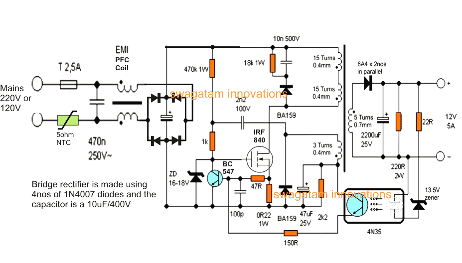
How to Wind the ferrite transformer
The ferrite transformer is wound over a 15mm EE ferrite core compatible plastic bobbin.
The one half primary is wound first, using a 0.4mm super enamelled copper wire (15 turns).
Secure the end of this on one of the primary side pins of the bobbin. Cover the winding with a layer of insulation tape.
Next wind the secondary winding (5 turns) using 0.6mm wire over it.
Terminate the ends on the secondary pins of the bobbin.
Apply insulation tape over this winding.
On this wind 3 turns of 0.4mm auxiliary winding, cover it with insulation tape.
Finally continue from the secured end of the first primary winding and wind 15 more turns over the above auxiliary wind to finish of the ferrite transformer coils.
Put a few layers of insulation tape to finalize the winding insulation.
Fix the EE cores and tape it yet again along its periphery.
Make sure the EE core edges are separated with an air gap through a piece of insulation tape or a paper, this will prevent core saturation and stalling of the desired smps induction.
THE CIRCUIT EXPLAINED ABOVE IS NOT ISOLATED FROM MAINS, AND THEREFORE IS EXTREMELY DANGEROUS TO TOUCH WHILE EXPERIMENTING IN POWERED CONDITION, AND ALSO THE DESIGN IS RECOMMENDED SPECIFICALLY FOR USERS HAVING ADVANCED KNOWLEDGE IN THE FIELD, NOT FOR THE NEWBIES..


Questions & Answers
Hi
Is there any reason why this kind is switched topology can't be used as a (constant voltage) power supply rather than a charger?
Hi,
a charger is also a kind of power supply so definitely smps circuits can be used as DC power suppies.
in fact smps itself stands for "switch mode power supply"
Hi,
can i increase the output volts to 36v or 24v?
yes you can do it by adding more no. of turns at the secondary side of the transformer.
.the opto zener will also need to be changed appropriately
thank you sir. this is the best place i found for projects.
please tell me a ckt for smps based 36v,2.5A supply
thanks to you a lot
thank you abhishek, If possible I'll try to present the design in my blog soon.
sir please can i use 1n5404 in place of ba159?
second question please what is EMI coil?
1N5404 will not work as it's not a fast recovery type of diode.
you can eliminate the EMI coil it's not compulsory.
U Can use 4937 in place of BA-159
ok sir but if eliminate the EMI coil that mean it should connect straight to the A/C plug? sir i went to electronic shop i asked them to give me ba159 diode but they said it not available only they have does not have a number but it a shape diode can it be use?.
biannz, you can connect the input directly without the EMI coil, it's there only for suppressing noise.
do not use anything that's not verified or is without a number…..I think your shop keeper sells old used parts ..is it?
dear sir i want to build the smps. i want to know what is Th-NTC used in this circuit?is it possible to use IRF640, or IRF Z44N mosfet in this circuit? can i change the value of the capacitor 10uf 400v with 3.3uf or 100uf…..just i want to know….please reply.
Dear Skl,
Th-NTC is a 350V NTC thermister.
Only those mosfets which ca handle in excess of 400V will work here, the ones you have suggested won't work
The input filter capacitor voltage should be rate at 400V, anything less will be unsafe.
Hi,
Nice blog and circuits!
I'm trying to drive a 1/4 hp three-phase motor with an atmega, for which I'll be using this setup:
https://drive.google.com/file/d/0B_0sypSANVUcdDA4SGxEcFpUOHc/edit?usp=sharing
The author told me I'd need 4 separate 12v supplies (3 for the high-side bridges, 1 for all low-side bridges would be fine).
Would it be too complex to split your 12V single-output 5A into 4x12V outputs? It seems I'd need 2A to switch my mosfets, though, being such a design also useful for using igbt's instead in a future.
Regards,
Hi Thanks! Saw this just now, so replying you rightaway!.
I can't suggest actually until I see the entire circuit diagram, because high/low side configurations could be crucial designs and need special care.
it's always better to go for the extreme safety measures, as much as possible, so using separate power supplies could be preferred
what is the purpose of using R220 2W at output?
it's for dissipating excess power and for aiding the zener stage, it may be removed though, since the inclusion is not crucial.
Hello,
is there any way to make this to be variable power supply?
And yes this is one of the best blogs I found for electronic projects!
Best regards.
Hi, thanks!!
You can try replacing the zener diode with a 4k7 pot and 22 ohm resistor with a 1K resistor, the pot could be used to vary the intensity of the opto LED allowing desired voltages at the output.
The LED anode will go to the center of the pot, the remaining free ends of the pot will connect with 1K and ground.
Thank you kind sir!
Sorry for disturbing again,
but is this transistor near ZD 16-18V in schematic actually part of 4N35?
It's inside the 4n35, an inside view of the opto.
check the datasheet of 4n35 for getting an exact idea about it.
Sir,
the size of the transformer is standard or the transfo which can hold these no. of winding can be used?
the one which would hold the turns comfortably must be used.
thanks sir…
Sir, Give me no of transformer used in your circuit
The transformer winding details are given in the article.
Sir,
Is there any way to increase the amp of this circuit..Like 8a or 10a
Syed, use more number of wires in parallel while winding the secondary turns, this will proportionately double or triple the current rating of the system.
Thanks You…
Sir BA159 is not available in my city. I have checked all the shops.
can i use any 1000v , fast recovery diode
yes, any similar 1kv fast recovery type diode will do.
Sir can you suggest me any diode instead of ba159 or otherwise i will try other fast rectifier diode..
I have seen a NTC in the ballast circuit of 25 watt CFL ..Can i use that one..
I am waiting for your reply
Syed, any equivalent fast ercovery diode will do.
yes, the specified NTC could be used
Sir can i use gpp20j instead of ba159..
shopkeeper said that i should work in this circuit..
Syed please check its datasheet, if it's a 1amp/300V fast recovery type diode then there's no problem using it.
Diode Type Standard
Voltage – DC Reverse (Vr) (Max) 600V
Current – Average Rectified (Io) 2A
Voltage – Forward (Vf) (Max) @ If 1.1V @ 2A
Current – Reverse Leakage @ Vr 5µA @ 600V
Speed Standard Recovery >500ns,>200mA (Io)
Does it work here, It is standard recovery diode??????
If it's mentioned "fast recovery" in the datasheet, then it can be surely used.
HI! Sir, tell me please number of turns for the primary and secondary auxiliary transformer ETD 29. Wire diameters of bobbin.Not have EE core 15mm
Hi Dragos, no changes are required it's exactly the same as mentioned in the above article.
sir i want to make power supply for 1watt LED drive. I want 24 – 36 volt dc supply at 5amp. because i m not electronics knowledge i am not understand coil turn even i don't see what are the material. please can you design another circuit if possible or please guide me or send me video on ashokagreatking06@gmail.com please help me. I already search in your blog also post comment in another post regarding LED drive for ceiling lights.
Ashok, you don't need to make the power supply, you need to buy it from the market. Your main project is LED lighting not the power supply, so please buy it for the market and use it for your purpose.
can we use computer SMPS for supply as i check out SMPS 450watt it gives 12volt 20A. Is it useful as it gives warranty? Is it useful for LED driver?
yes will do, and now since the LEDs are connected in series, parallel mode the 1.5meter distances will have no effect or minimal effect.
ok so sir can now we can connect LED in grid of 0.5m X 0.5m using any computer SMPS. right sir? Thank you for guidance.
yes can be done as per the series/parallel instructions and the formulas given in the other article..
Sir i have tried that circuit with GPP20j diode but the fuse always broken?
Syed, if the fuse is blowing it could be due to some other fault in the circuit, not because of the diode….you may have to seek help from an expert for troubleshooting the actual fault.
Sir, What kind of bobbin do you use to wind the transformer? do you have bobbin dataheet?
Any bobbin recommended for 15mm EE core can e used, an example image of the E cores can be seen here:
B should be 15+15 = 30mm
is it Okay if i use Ferrite Bobbin Core EE22PL3K /Ferrite Bobbin Core EE25R3K ?
yes, any ferrite core bobbin assembly is ok as long as the winding fits in it comfortably…
Hai…I'am Lalar…
How do you determine Freq Switchingnya?
And how many Switching Freq and Freq Osc you use on this circuit?
if I can replace the transformer with ETD49 order to get the V out and I out more by scematic this? and how comparisons Primary Coil and Secundernya?
Hi, frequency is determined by 470k, 1k, 2n2, one frequency oscillator only.
any suitable EE core will do for the project.
Dear sir,
What do you mean by "EE core have air gap in end " . if I apply varnish coat on single E E core . Would that gap be enough.
Thanks and regards
air gap refers to the small gap made by inserting paper or a layer insulation between the end surfaces of the two E core where they merge together.
One more thing Sir, can you discribe breifly the Dimension of transformer.
Thanks and Regards
please see the reply given to OKIF in the previous comments.
Hello sir,
You have any idea in transformer winding. I am assembling 55-0-55 with 12 amps.. I am doing E I lamination .I calculated all specification like No. Of turn,Gauge etc. I want to buy EI lamination stamping. Wat detail or specification I have to give
to shop owner.
Thanks and regards
Sorry, I have no idea regarding the lamination data….so I won't be able to provide any help.
However, if you happen to build it successfully feel free to shear your experience and data regarding the same, will appreciate it a lot.
Hello Sir
I have done only calcultion sir.still everything is in paper only.i dont know how to order raw material.Definitely I will give all detail … How to load complete detail can you tell me,actually its quite long,including gauge table and cross section table.or can I put directly into comment column?
Regards
Thanks style, you can provide the data to my email ID which is given in the "contact" page below:
https://www.homemade-circuits.com/p/contact.html
Hello Sir .
I will give all data whaterver I had to your email I'd within couple of days
Regards
no problem style, take your own time and do it nicely 🙂
can i change output voltage from 11.5 to 14.5 v dc via preset.
if yes pl suggest me preset connection with preset value.
use a 15V zener in place of the shown 13.5V zener
thanks sir
but i want to place preset for selection of voltage range from 11.5 to 14.5vdc?
kindly suggest me preset value with connection.May i connect 22 ohm preset in series with zener 15v?
remove the zener and put a 1K preset there….connect its one lead to ground, one lead to 22 ohm and the center lead to the opto LED anode
Respected sir
i want to buy 02 complete ckt with preset.kindly help me , If u have ready then give me your contact detail & id.
Dear Nitesh, I don't manufacture electronic circuits so I won't be able to provide to you, you can easily buy it from your local electronic market, these units have become very common nowadays.
Dear sir
ok
thanks
sir
Generally all 12v /5 amp smps consist min 47 mfd or 68mfd/400v as a input bulk capacitor .so in this ckt 10mfd/400v bulk capacitor for capable for handle full load?
i want to use this ckt as cctv smps.12v /5 amp
kindly inform me core grade, value & make I mean which AL value of core i used? & primary inductance also?
does 2 nos of 6A4 handle min 4.5 amp? Or any heating issue?if u run this smps constant up to long time min 12 hours?
Nitesh, the AC input filtration is not so crucial, a 10uF is OK considering the fact that the output of the transformer has a much larger filter capacitor in the form of 2200uF capacitor
the transformer can be built on any suitable EE core and bobbin, the winding details are provided in the article, I have no idea about the inductance values.
actually a high speed diode must be used in place of the 6A4 diodes, but you can go with the 6A4 diodes also, a single 6A4 will also work.
sir
ok
thanks
Hello Swagatam
Some of your readers may not have understood that the little dots indicate polarity of the windings on the transformer. Get them wrong and you have a fried Mosfet! BY 199 and UF5404 can be used to replace the BA157
Hello Xavier, thanks for your concern, but it may not be so critical…one has to simply follow the connection pattern of the winding exactly as given in the diagram for the primary,,,,if the lower auxiliary winding is connected wrongly by mistake would not do any harm to the devices, the system will not function that's the only thing that may possibly happen…but no mosfet will burn or get damaged.
The secondary is irrelevant, since it has only a single start to end winding.
Hello Swagatam
Secondary polarity does make a difference, in my experience. If you scope the secondary AC output, you will see that it is asymmetric (eg more negative-going than positive). So if it is connected with wrong polarity, the SMPS has to work harder for the same output.
Thanks Xavier, the diode and the capacitor polarity must be done according to the "dot" for the secondary, that's correct, but suppose if it's done the wrong way, in that case the output will simply show no voltage according to my simulation…because the output from secondary are ordinary rectangular waves, with positive peaks at the "dot" side of the winding.
Dear tell me the complete action of circuit. why u did not used any pwm controller like uc3842,sg3525,tl494.
Irf840 mosfet cannot be used in flyback like u sugested, it has vds=500v(max), a flyback mosfet must be rated @ 2 x bus voltage + marging. that is 2 x 311v = 622v. Dat means a 700v mosfet and above is going to be used.
hello sir , i want to make a 8v,500ma & 5v ,300ma power supply in a 8051 ckt, in my opinion for this i should use double winding in secondary & reduce the thickness in secondary winding & change the zener.
sir plz guide me
hello anutosh, you can at the most reduce the secondary wire gauge suitably, and change the zener to 8V or 5V that's all, no other changes would be required
hello sir, in my previous question i want to make both o/p in single supply ,for it in can i use double winding togather & apply zener on 5 v supply only
ashutosh, you don't have to put two winding, simply calculate it for 8V out and then add a 7805 IC with the output, so from the same winding you can achieve 8V and 5v together
Hello Sir, Could you help me design a power supply circuit with output voltage varying from 3V to -3V and current varying from 2A to -2A?
Thank you
Hello spoorti, presently i do not have this circuit with me, if I get it will surely publish it for your reference.
This circuit have under test before? i will try it for my project, thank you sir
Regard
yes it is a tested design, but it is not recommended for the newcomers
I have a smps from a vcr which gives 5v and 12v but I don't know the ampere . I connected the 330v dc output to the smps wrongly suddenly my switching transistor blasted . Since the vcr was made in 1995 now I couldn't get that transistor. The transistor was TOP201Y and I checked for an equivalent that was TOP223Y but all were discontinued so I couldn't get it in any shops but data sheet says it's a 50w switching transistor so can u suggest me any switching transistor for this purpose
It's not a transistor actually, it's an IC, and I am afraid there's no direct replacement for this switching feedback IC. There's one alternative in the form of TNY tiny switch but the configuration for this IC is different to the TOP IC in terms of their connections with the opto coupler…so it won't be of any good either.
Hello Swagatam, i need you to explain why the primary winding turns is as low as 15T.
i understand the formula N= V * 10^8 / 4 * f * B * A is normally use to determine ferrite core winding. Is the this applicable here too? Because i use the specification of ETD39 to calculate the primary winding as per the circuit above. i got a primary turn of 103 @ 40kz.
But you recommended 30 turn be use for primary. Am i getting something wrong with my calculation? Also i though the turn ratio of the transformer is always close to the vin/vout ratio. looking at the circuit we are converting mains voltage(310dc) down to 12vdc. the voltage ratio in this case is not close to the turn ratio of 30/5. please can you educate me on this?
Hello TonyBen,
The above circuit was not designed by me. Your assumption appears to be valid, however the relatively lower of number of turns in the design could be to allow higher current because as we all know that as the number of turns in a winding increases its ability to pass current decreases, so that could be one good reason of using lower number of turns.
Another factor could be the use of higher frequencies, because higher frequencies will allow lower number of turns to be used, and vice versa.
I would suggest you to go ahead according to your suggested formula results, and in order to increase current you can use many number of parallel strands for the primary winding, let's see how it performs
Hi Swagatam!
I have viewed your articles about smps, and i am so proud to find your site;
the reason I was so fascinated by your designs is because I want to build a simple inverter which can give 300Watts to power my ceiling fan, small radio, light and charging phone.
I have tried one and it produces 203ACV from 12dcv supply just by increasing the secondary turns, I only tested it to power two 100W filament bulbs (not too bright) and two 18Watts energy server light. and it was working great without heating plus its not heavy at all !!!!
But some thing come up, that those smps are operated by using high frequency, how can I get 220ACV 50-60Hz?
Thanks again, and I am only waiting for you to inbox or if it happen you make an article about that please notiffy me.
thanks again
Thanks Raymond, appreciate your response!
I have one example ferrite core inverter design in my blog which comprehensively explains the method of converting the high frequency stepped up voltage into 50Hz output, you can learn it here:
https://www.homemade-circuits.com/2014/07/5kva-ferrite-core-inverter-circuit.html
here's another design explaining a similar concept:
https://www.homemade-circuits.com/2015/05/smps-mains-voltage-stabilizer-circuit.html
plz
choper ki calculation kese hain???????????????
bataein plzzzzzzzzzzzzz
transformer calculations plz
btaein
choper ferrte calculations kya hain??????????////
the details are given at the bottom section of the article