In this post I have explained how to make a 0.6V to 6V or 12V boost converter circuit using a single chip MC74VHC1G14, which uses under 1V to operate.
About the IC MC74VHC1G14
Normally, we all know that a silicon transistor would find it difficult functioning below 0.7V, unlike germanium counterparts which are capable of doing it with ease, however nowadays we don't often hear about these devices which have become quite obsolete with time.
The circuit discussed here uses an inexpensive Schmitt trigger NOT gate MC74VHC1G14 from the 74XX TTL family which are designed to work with voltages well below 0.6V, to be precise even with as low as 0.45V. The device we employ is manufactured by Motorola.
The presented 0.6V to 6V boost converter circuit can be even modified to achieve upto 12V from a 0.6V source.
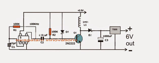
Referring to the figure below, we see a rather straightforward set up consisting of an oscillator stage using a single NOT gate inverter module as discussed above.
You can also try a Joule Thief Circuit for getting similar results.
Another design explains a 1.5 V to 3.6 V boost converter circuit
Circuit Operation
This NOT gate is very special since it's able to oscillate even at voltage as low as 0.5V which makes it very suitable for the present 0.6V to 6V or 12V boost converter application.
The oscillation frequency here is determined by R1 and C1 which is calculated to be around 100kHz.
The above frequency is fed to the base of an NPN transistor for the required amplification.
C2 makes sure the two IC and the BJT stages are kept isolated from direct contact in order to avoid the low input voltage from dropping below 0.5V
R2 and thee schottky diodes D1 keeps the BJT sufficiently biased for helping an optimal oscillatory response for the transistor.
D2 is another schottky diode which is introduced to keep the charge from C3 disconnected during the switch OFF periods of Q1 otherwise the stored charge inside C3 could get discharged or shorted via Q1.
The IC 7806 at the output is to maintain a fixed 6V irrespective of the boost level created by L1 and the associated converter stages.
L1 must be wound strictly over a ferrite core. The dimension and data of the coil is a matter of some trial and error or it may be procured as a ready made unit for the same.
Circuit Diagram


Questions & Answers
HI bro,
If i use 7805 inserted of 7806..than it use as a smartphone charger..??
Hi bro, both will work and can be used according to me.
Sir can u recommend a circuit tha boost li ion bat 3.7 v to 5 v for android phone charger, tnx Sir!
Jindro, you can use the Joule Thief Circuit as discussed in the following article
https://www.homemade-circuits.com/make-this-power-bank-circuit-using-37v/
may i know the code of the diode use here, i am going to try also
you can try BAT41 for the diodes
Hello,
do you have any recommends for a similar IC ?
I dont can find and get this IC on a cheap way. Do you have any recommends, does it need to be a Very High Speed CMOS?
Thanks
hello, I am not sure about an equivalent IC, but a joule thief idea is one option which can be tried for achieving the same results.
Does it depend on the NOT gate or the TTL variant ?
I really want use it, but I can not get this right one.
please check its datasheet.
thanks neha!
No it can't be used since a lemon would not produce sufficient current required for the boosting action….
How to connect the circuit of 0.6V to 6V/12V Boost Converter
my mail is: camaradiop001@gmail.com
How to connect the circuit of 0.6V to 6V/12V Boost Converter
my mail is: camaradiop001@gmail.com
the scheme of 0.6V to 6V/12V Boost Converter Circuit is complete?
how the connection to have 6 v at the output of the system.
the circuit complete, and you must build it exactly as its shown….click on the diagram to enlarge it.
Hello. Thanks for the reply. I would like to have a precision compared to al voltage input and sortie.de more I see + 0.5 v at the top of the schema.le less will be connected where.
Hello, the circuit can be used for converting as low as 0.5V into 6V provided the input current is high.
What is the number of turns it takes to the coil around the ferrite. If I use 6 v to the entered, what would be the output voltage of the circuit.
for 6V you can use any 555 based boost converter, this circuit is recommended only voltages lower than 2V
you can also try a joule thief circuit for the same.
Hi Swagatham,
I want a 24VDC to 48VDC boost converter.
I got a 24DC battery as the voltage source.
How can I build one. Please suggest.
Hi Uday,
you can use any IC 555 based boost converter circuit from this website.
https://www.homemade-circuits.com/?s=555+boost
Thank You Swagatham,
I am need of a circuit where the voltage should decrease gradually over a specified range. As an example it should decrease from 15VDC to 5VDC continuously, but not as in one step, so that I can have control on the rate at which it is decreasing.
Can you recommend something for this?
Thanks a lot
Uday
Uday, you can probably implement it using a PNP emitter follower BJT circuit, where a base/emitter capacitor would decide the slowly declining voltage across the emitter and positive supply of the BJT
Thanks Swagtham it worked.
Thanks a lot!
You are welcome Uday, happy to help!
Hi swagatam
which battery do you recommend to be use in the Vin? can we use wrist watch battery 1.5V input if size is of utmost important in a given project? thanks alot.
Hi Abba, you can try any type of battery, size is not important but the output current will be as per the AH rating of the battery and proportionately reduced depending on boosted value of the output voltage
Hi,
I would like a circuit to optimise the power of NiCad cells to drive Ultra Bright Leds.
I have 3 cell Nicad packs rated at 3.6V which I’d like to use to drive the Ultra Bright Leds.
To optimise the power available in the NiCad cells, I’d like the cells to continue to drive the Leds with a constant current as the cells voltage drops below the Ultra Bright Leds rated voltage.
I was considering a Joule Thief Circuit or Voltage Doubler feeding a Constant Current circuit.
Any suggestions/circuits please ?
Hi,
you can try the first circuit from this post:
https://www.homemade-circuits.com/how-to-make-simple-boost-converter-circuits/
However current may not remains constant and may also drop as the voltage drops.
Hey,
Can you please give the link of the website where I can get IC MC74VHC1G14?
Hi, if you do Google “Buy MC74VHC1G14” you will find many reputed online sources who are selling this chip.
Hi Sir. May i know how u calculate the value of capacitors,resistor and inductor needed to boost the input voltage?
Hi Amirul, the basic principle is the same for all boost converters, yu can read it in details in the following link:
https://www.homemade-circuits.com/how-boost-converters-works/
So your calculation for the components rating based on the link above?
And may i know what software did you use for this circuit simulation?
I did not use any software, I just built it practically, it was a long time ago.
Sir i want a voltage booster circuit capable of delevering 6 vdc 3 amp
INPUT voltage wouldbe 3 vdc
kindly guide me
what is input amp?
Less then.5 amp
you can use the 555 circuit from this article
https://www.homemade-circuits.com/how-to-make-simple-boost-converter-circuits/
use 5 turns for the coil, and the IC should be LMC555
Swagatam, Nice web page !
I was looking at using a voltage regulator that would buck and boost, I found the following circuit on Wiki and it looks like the zener could be replaced with any value that you wanted to output voltage to be ?
Also uses a lot of very simple components. I want to conserve as much of the battery as possible.
Maybe even a voltage divider that would allow you to adjust a pot to any output value say 1 – 7volts.
https://en.wikipedia.org/wiki/Joule_thief#/media/File:Regulated_Joule_Thief_generalization_and_cleaning.svg
Thank You.
Thanks Eli,
yes that’s a simple Joule thief circuit with a feedback link for controlling the output voltage to a specific limit as determined by the zener value.The zener could be replaced with a potential; divider for getting an adjustable output level.
Swagatam, Thank you for the prompt reply.
I want to know some more about the component selection.
1. What do those the two dots on the transformer stand for ? And is this a torrid coil ?
2. I see a lot of designers using all types of transistors, and then others build the entire circuits from 2N2222(s). Do the characteristics of those other transistors that specific ?, or are developers using whats laying around on the workbench ?
3. Is the LDO really needed ?, Looks like a power waster to me ? (why not just an LC filter?)
Thanks
Hi Eli, those dots indicate the start an finish orientation of the winding turns. You can ignore and wind the turns anyway round, if it doesn’t work in the circuit, just swap (interchange) the ends of any one of the winding.
Only the collector current and the collector voltage specs is what really matters for the BJT, which must be higher than the required load V and I specs, est are not critical unless the applications is something very special with special requirements.
The LDO IC may be necessary if the load involves TTL ICs or any parameter with strict 5 V requirement, otherwise it can be ignored
Hello good afternoon I am a follower of your website since its inception. I need a circuit to convert 3.7vdc / 4vdc to 9vdc to use in the voltmeter with 18650 batteries. A simple and small circuit Thank you very much
Thank you Carlos, for being a dedicated follower of this blog.
You can use the basic joule thief circuit for your purpose.
You can adjust the transistor side turns of the coil, or the secondary side until the required level of output voltage is achieved
Hello good afternoon. Thanks for your answer, I like this circuit but I can’t get the Hello good afternoon ic. Thanks for your reply, I like this circuit.. but I can’t get the ic MC74VHC1G14. The question is .. Can I use another IC? Thank you very much
You can use a single gate from the IC 4093 as shown below:
However all these ICs require minimum 2 V to operate, so I am not sure how they can be applied to work with 0.6V??
The article above was referred from another website!
Using a search engine for the internet gives many results of the IC, but it looks hard to solder. I wonder if there is a germanium IC with a breakout board available somewhere?
GOOD JOB SWAGAT, i am working on wind turbine project getting .5v ac how can i boost this to 5v
Thank you Sheela,
To boost 0.5v you can try a joule thief circuit as I have explained below
https://www.homemade-circuits.com/1-watt-led-driver-using-joule-thief/