This LED flashlight circuit is able to power a Luxeon type LED with a single 1.5 V battery. This results in a miniature flashlight that will not run out quickly. By: P. Martin
Basically it is a boost converter circuit which boosts the 1.5 V DC from a AAA cell and converts it into a 3.3 V output. This boosted 3.3 V is then used for powering a 3.3 V LED with high brightness.
Circuit Description
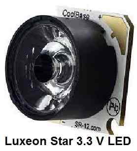
Commercial white LEDs operate at 3.42 V for Luxeon (see Figure 1), and 3.6 V for more typical high-brightness models. The main task of the circuit will be to increase the only available voltage of 1.5 V.
The principle is that of a "boost" converter or parallel inductor chopper.
Figure 2 provides the detailed schematic.
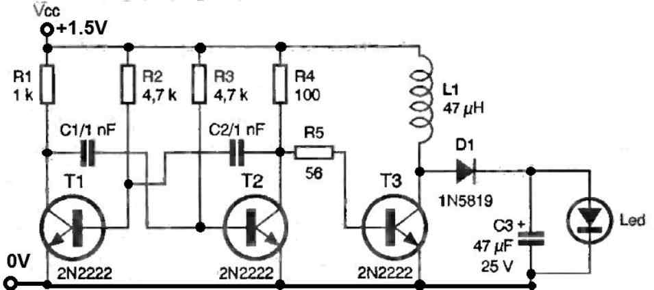
The two transistors T1-T2 constitute an economical first multivibrator whose frequency is around 60 kHz.
This square "driving" signal is then applied to transistor T3, which will either allow or prevent current from passing through the inductor L1.
During each half-cycle where the transistor is conducting, the inductor stores energy in a magnetic form, while capacitor C3 charges.
During the next half-cycle, if transistor T3 is off (open circuit), the energy stored in the inductor is added to that stored in capacitor C3 through diode D1.
The use of a Schottky diode (1N5819) here will improve performance due to its lower voltage threshold and faster response time.
The inductor should have a relatively low series resistance of about 0.1 Ω. The overall efficiency of the circuit is approximately 70%, which is a minimum in the world of switch-mode power supplies, but our circuit is quite simple.
A high-brightness white LED (3.6 V / 25 mA) can thus be powered at full power. In the case of using a "Luxeon Star/0" LED (with integrated optics), the voltage will drop to 3 V.
The LED will therefore be slightly underpowered, but given its efficiency, the beam will remain surprisingly powerful.
Caution: Do not look directly into the LED to avoid eye damage!
Construction
The single-sided printed circuit board and component placement (Figures 3 and 4 below) presented here have been miniaturized to allow all components to fit on a 25 x 25 mm board.
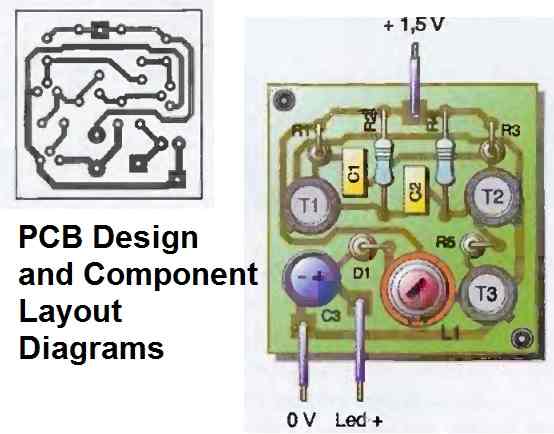
This corresponds to the base of a "Luxeon Star/0" LED on which the printed circuit board can be mounted with two nuts and spacers.
If necessary, a square plastic plate can be inserted between the two to isolate the LED heat sink from the printed circuit board solder joints.
Figure 5 shows the variation in light intensity of the "Luxeon Star/0" powered by the circuit and a low-cost alkaline AA battery, providing an idea of the duration of the lighting obtained.
After twenty hours of operation, it is still possible to read in the dark.


Questions & Answers
Hi,
Is there a way to keep a LED on, in a 3V battery, for a long period, say 6 months?
Best Regards.
Nélio.
Hi, That may be possible, but not for 6 months, rather maybe for 1 month continuously.
You can try a joule thief circuit for that.
Instead of using 3V you can use try two 1.5V cells in parallel.
https://www.homemade-circuits.com/flashlight-circuit-with-long-backup-and-high-efficiency/
I like this circuit. I’ve been looking for a simple circuit to do this using discrete components.
Could you provide me any tips on how I can modify this to provide the same output voltage from 2xAA NiMh cells in series (each 1.2V, therefore 2.4V total but typical operation down to 2.0V). I want to see if I can squeeze the components into an old-style incandescent torch housing that takes 2xAA’s
Glad you liked this circuit. You won’t require any modifications in the circuit for your 2V DC input, you can use the design as is.
Good info., thx.