In this post I have explained a step by step construction of a "helping third hand" unit for assisting PCB soldering jobs in order to make the job much hassle free. The gadget could be very handy especially for the new hobbyists.
The project was constructed and submitted by Master Ss kopparthy.
I have explained the whole procedure.
The Circuit Concept
Dear sir, I am ss kopparthy.
Here I am going to give explanation, making procedure, parts needed, features, and everything else step by step how to make a HOMEMADE HELPING THIRD HAND.
FOR SOLDERING WITH FUME EXHAUST.
Here's how....MATERIALS NEEDED:
1)Wooden plank, preferably 9 inch length and 5 inch width and thickness 2 centimetres,
2)Drilling machine, drill bits,
3)cutting pliers,
4)Glue gun or any sealing agent like m-seal,
5)Three crocodile clips,
6)Flexible spiral steel tubing, or a strong steel wire will do, 4 metres or as per requirement,
7)Two or more white LED's and a 12VDC cpu exhaust fan,
8)12V dc adapter,9)some connecting wires and10) soldering iron with soldering tools11) Four wooden pieces of dimensions-1cm thick, 2cm length and 2cm height.
CIRCUIT DESCRIPTION:
This helping hand is very easy to make and it includes a feature of sucking away the poisonous fumes that come while soldering and it has two white Led’s which provide better vision while soldering.
You can even include more LED’s in parallel with existing LED’s using 1k resistors if you want and fix the LED’s to the fan using glue or you can even use separate tubings for LED”s so that you can point those LED’s on the particular place while soldering……
MAKING PROCEDURE:
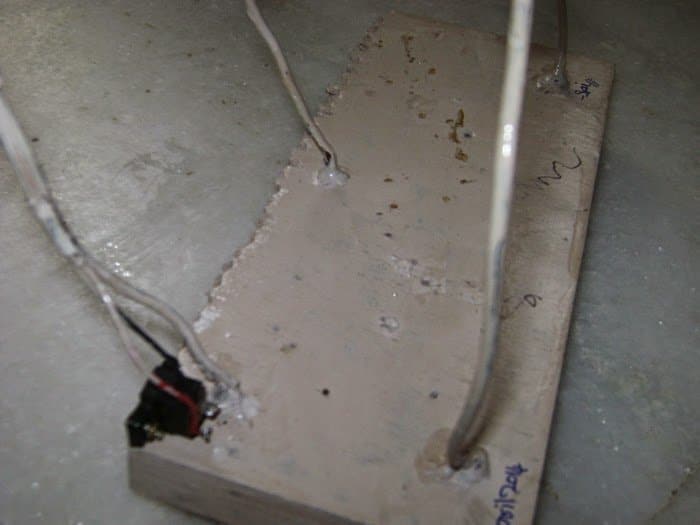
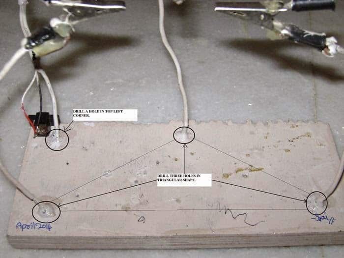
First, take the wooden plank and drill holes such that they form a triangle when joined. Next drill a hole in the top left corner of the wooden plank for fixing the exhaust fan’s steel tubing on whose top the fan will be fixed and LED’s.
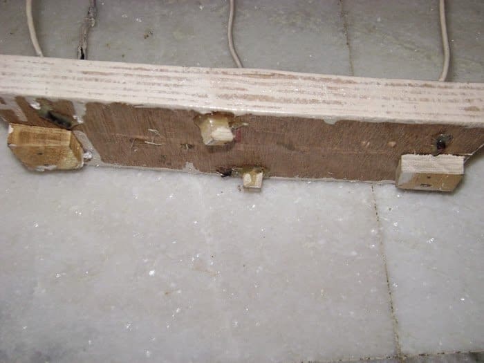
Now take four wooden pieces of dimensions 1cm thick, 2cm length and 2cm breadth and fix them at the bottom side of plank on the four sides so that the steel tubing that comes out when fixed, does not affect the stability and the entire instrument stands on the four wooden pieces (please let the “drilling holes" and “fixing wooden pieces”photos come here while posting in blog).
Now take three steel tubings of equal length and fix the three tubes in their place(i.e., in the three holes that are drilled previously in the shape of triangle.) using hot glue or m-seal(make sure you fill the entire hole).
Next take another steel tubing whose length should be 4-5cm more than the previously cut tubes.
Fix this tubing in the top left corner hole using hot glue or m-seal ( you can even cut two of such tubings and fix them at a distance which should be equal to the distance between two adjacent holes of fan so that the fan would be more stable).
Let it dry for 4-5 hours. After this take three crocodile clips and push the steel tubing into the clip. And fix it using hot glue and do the same for other two.
Let it dry for some time. In the meantime, take the exhaust fan and fix the LED’s in the front two holes using glue and connect the LED’s and fan in parallel and use 1k resistors for white LED’s and bring the final wires to the bottom and connect them to the female DC jack.
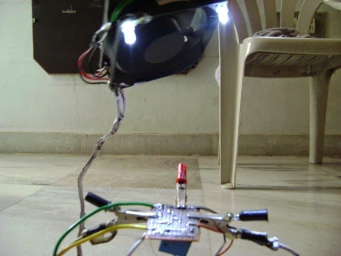
And next, fix the exhaust fan to the steel tubing that is on the top left corner by pushing steel tubing into one of the holes of fan using hot glue or m-seal(use more glue otherwise the fan would not be stable while on use).
Fixing the DC Jack
Now fix the DC jack beside the exhaust fan’s tubing on the plank using hot glue or glue drops.
Now keep the entire instrument aside for drying. After drying, you may paint the wooden plank with any color as per your liking.


Questions & Answers
Thumbs up for u SS, this gives me an idea 🙂
You are welcome Jindro!!
This is really a good job…. nice ideas the exhaust n the clips…. even iam experiencing the lack of a helping hand, even i have thought of a exhaust…. Thanks to the young minds behind this.
Nice ideas made brilliant…..
Thank you very much. Half of the credit goes to the genius, Swagatam sir….as without his encouragement, my idea would not have reached all of you…….
Hi S.S. Kopparthy
You could have finished this project more neatly.
Any, nice job. Thanks to you and of course our Guru jee, Swagatam.
@Abu-Hafss– Thank you….. and Thank you swagatam sir…
Oh, then really he has done a remarkable job.
S.S. Kopparthy, well done……keep it up.
Thanks Abu-Haffs (for calling me Gururjee),
Mr. SS is just 12 years old so maybe whatever he did should be applauded:)
Dear sir, thank you very much…..I think it would look better without those messages in brackets….which tell which photo to come after certain paragraph…….as those messages are to aid you while posting here…….. and else looks very good… and I dont know how to thank you for spending your more than the most valuable time to post my idea here. I can never forget you and your help at any cost…….
Thanks SS, I'll check your email and respond soon.
OH yes, sure sir thats a golden oppurtunity for me.Please check your mail(home made circuits@gmail.com) once.
With best regards,
Sai Srinivas.K
Removed! thanks!
SS you can feel free to post more such posts whenever you want, I'll happily publish them in my blog:)