In this post I have explained 2 simple universal current controller circuits which can be used for safely operating any desired high watt LED.
The universal high watt LED current limiter circuit explained here can be integrated with any crude DC supply source for getting an outstanding over current protection for the connected high watt LEDs.
Why Current Limiting is Crucial for LEDs
We know that LEDs are highly efficient devices which are able to produce dazzling illuminations at relatively lower consumption, however these devices are highly vulnerable especially to heat and current which are complementary parameters and affect an LED performance.
Especially with high watt LEds which tend to generate considerable heat, the above parameters become crucial issues.
If an LED is driven with higher current it will tend to get hot beyond tolerance and get destroyed, while conversely if the heat dissipation is not controlled the LED will start drawing more current until it gets destroyed.
In this blog we have studied a few versatile work horse ICs such as LM317, LM338, LM196 etc which are attributed with many outstanding power regulating capabilities.
LM317 is designed for handling currents up to 1.5 amps, LM338 will allow a maximum of 5 amps while LM196 is assigned for generating as high as 10 amps.
Here we utilize these devices for current limiting application for LEds in the most simplest possible ways:
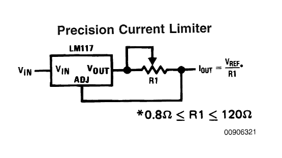
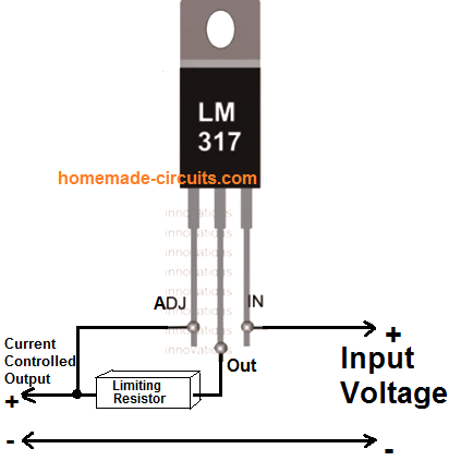
The first circuit given below is simplicity in itself, using just one calculated resistor the IC can be configured as an accurate current controller or limiter.
Calculating the Current Limiter Resistor
The figure shows a variable resistor for setting the current control, however R1 can be replaced with a fixed resistor by calculating it using the following formula:
R1 (Limiting Resistor) = Vref/current
or R1 = 1.25/current.
R1 wattage = R x I2
Current may be different for different LEDs and can be calculated by dividing the optimal forward voltage with its wattage, for example for a 1watt LED, the current would be 1/3.3 = 0.3amps or 300 ma, current for other LEDs may be calculated in similar fashion.
The above figure would support a maximum of 1.5 amps, for larger current ranges, the IC may be simply replaced with an LM338 or LM196 as per the LED specs.
Application Circuits
Making a current controlled LED tubelight.
The above circuit can be very efficiently used for making precision current controlled LED tube light circuits.
A classic example is illustrated below, which can be easily modified as per the requirements and LED specs.
30 watt Constant Current LED Driver Circuit
Assume the LEDs to be 3.3 V, 10 watt, and Supply input to be 12 V
Current of LED becomes = 10 / 3.3 = 3 amps
The LM338 current limiter can be calculated using the formula
R1 = 1.25 / 3 = 0.41 Ohms
Wattage = R x I2 = 0.41 x 3 x 3 = 3.69 watts or 4 watts
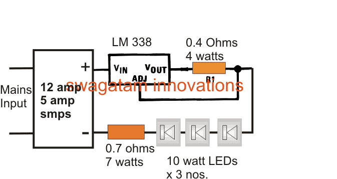
The series resistor connected with the three LEDs is calculated by using the following formula:
R = (supply voltage – Total LED forward voltage) / LED current
R(watts) = (supply voltage – Total LED forward voltage) x LED current
R = [12 - (3.3+3.3+3.3)]/3amps
R= (12 - 9.9)/3
R = 0.7 ohms
R watts = V x A = (12 - 9.9) x 3 = 2.1 x 3 = 6.3 watts
Restricting LED Current using Transistors
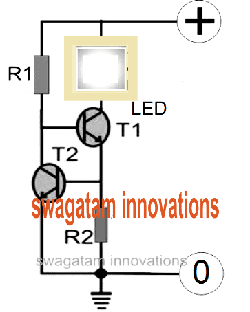
In case you do not have an access to the IC LM338 or if the device unavailable in your area, then you could simply configure a few transistors or BJTs and form an effective current limiter circuit for your LED.
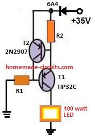
The schematic for the current control circuit using transistors can be seen below. The design is an example for a 100 watt LED current limiter, with 35V as the input supply and the 2.5 amp as the maximum current limit.
PNP Version of the Above Circuit
How to Calculate the resistors
In order to determine R1 you may use the following formula:
R1 = (Us - 0.7)Hfe/Load Current,
where Us = supply voltage, Hfe = T1 forward current gain, Load current = LED current = 100W/35V = 2.5 amps
R1 = (35 - 0.7)30/2.5= 410 Ohms,
Wattage for the above resistor would be P = V2 / R = 35 x 35 / 410 = 2.98 or 3 watts
R2 may be calculated as shown below:
R2 = 0.7/LED current
R2 = 0.7/2.5 = 0.3 ohms,
wattage may be calculated as = 0.7 x 2.5 = 2 watts
Using MOSFET for Higher Current Applications
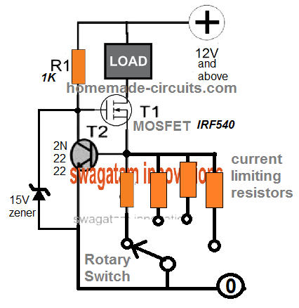
MOSFETs are more efficient than BJTs in terms of handling higher current and wattage. therefore, for applications that require high current limiting, for high wattage loads, a MOSFET can be used in place of T1.
The current handling capacity of the MOSFET will depend on its VDS and IDS ratings, with respect to the case temperature. Meaning, the MOSFET will be able to tolerate the amount of current defined by the product of its VDS x IDS, provided the case temperature does not exceed 40 degrees Celsius.
This may appear practically impossible, therefore the actual limit will be defined by the amount of VDS and IDS that allows the device to work below the 40 degrees Celsius mark.
The above BJT based current limit circuits can be upgraded by replacing T1 with a MOSFET as shown below:
The resistor value calculations will remain the same as discussed above for the BJT version

Variable Current Limiter Circuit
We can easily convert the above fixed current limiter into a versatile variable current limiter circuit.
Using a Darlington Transistor
This current controller circuit features a Darlington pair T2/T3 coupled with T1 to implement a negative feedback loop.
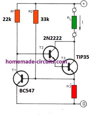
The working can be understood as follows. Let's say the input supply the source current I starts rising due to high consumption by the load for some reason.
This will result in an increase in the potential across R3, causing the T1 base/emitter potential to rise and a conduction across its collector emitter.
This would in turn cause the base bias of the Darlington pair to start getting more grounded. Due to this the current increase would get countered and restricted through the load.
The inclusion of R2 pull up resistor makes sure that T1 always conducts with a constant current value (I) as set by the following formula. Thus the supply voltage fluctuations have no effect on the current limiting action of the circuit
R3 = 0.6 / I
Here, I is the current limit in amps as required by the application.
Another Simple Current Limiter Circuit
This concept uses a simple BJT common collector circuit. which gets its base bias from a 5 k variable resistor.
This pot helps the user to adjust or set the maximum cut off current for the output load.
With the values shown, the output cut off current or current limit can be set from 5 mA to 500 mA.
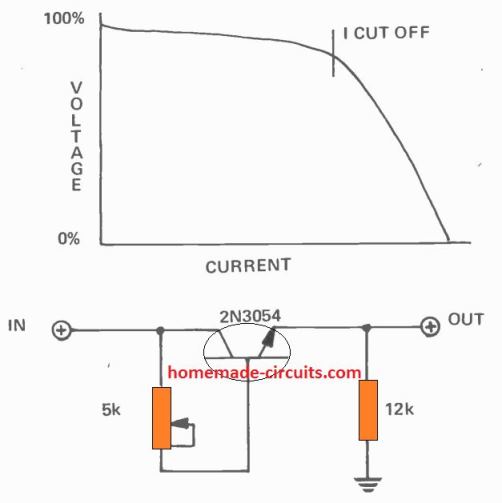
Although, from the graph we can realize that the current cut-off process is not very sharp, yet its is actually quite enough to ensure proper safety for the output load from an over current situation.
That said, the limiting range and accuracy can be affected depending on the temperature of the transistor.
Adjustable Current Controller Circuit using IC 741
The following IC 741-based arrangement can be used if you want a preset current limit which is adjustable across a wide range.
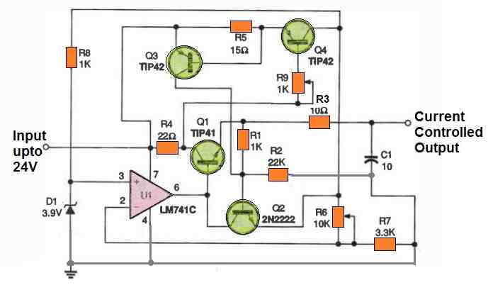
When R9 is adjusted to zero ohms, the lowest current limit for the components depicted is around 47 mA. Add a suitable fixed-amount resistor in series with R9 if you want to set a specific high current limit.
As you can clearly see, implementing current crowbars offers the excellent method of safeguarding electronics from short circuit destruction.


Questions & Answers
Hello Dr.Swagatam.
I need a variable current circuit from 0 to 10 amps with a fixed voltage of 100 volts DC, such that voltage drop does not occur. With which circuit can I achieve the desired result? Please help and introduce a complete circuit. I also have a question: what type of circuit has very high efficiency for controlling and limiting current?
Hi Muller,
You can achieve the current limit using the following module, but your voltage might drop if the oad is not compatible wiith the voltage specifications…
https://www.homemade-circuits.com/50a-high-current-sensor-ic-acs758-circuit-diagram/
Hello Dr.Swagatam.
Thank you for your quick response.
I need up to 10 amps.
Is it possible to use the SY-10T instead of the ACS758?
And in an analog circuit without Arduino, do other components need to be changed?
Hi Muller,
Although I could not find sufficient information about its circuit connections, it seems like it should work with the 741 opamp circuit for implementing the adjustable 10amp current control…
full name is “SY-10 NANA Sensors” .
that sells of it link:
veswin.com/product-SY-10.html
please check: Is it possible to use the SY-10T instead of the ACS758?
And in an analog circuit without Arduino, do other components need to be changed?
thank you very much.
Where is the datasheet? Without datasheet and pinout diagram it is impossible to know about its working details.
Yes, the opamp circuit can be used without any changes…
Hello Mr. Swagatam
I need to build a simple current limiter for a controlled electrolytic process. As my electrolysis proceeds water resistance between electrodes will drop from approx. 150kΩ to 15kΩ. With a supply voltage of 24VDC the load current would thus increase from approx. 0.16mA to 1.6mA.
My intention is to automatically limit the load current to a maximum of 0.25mA irrespective of decreasing water resistance.
Questions:
1. In your circuit “Precision Current Limiter”, if I set R1 = 100kΩ will then the output load current (Iout) be limited to 0.24mA? Would that work in my case?
2. Can LM117/317 regulators even control such low currents accurately?
3. If all this fails, could you please recommend a simple circuitry that would do the job? Thank you much!
Hi Holgar,
0.25mA indeed looks very low and might not allow the lm317 to work properly, in that case why not use just a resistor in series with the supply voltage?
As per Ohm’s law, this Resistor could be:
R = 24/0.00025 = 96000 ohms or 100000 Ohms or 100k Ohms. This will be enough to ensure that the max output current to the water does not exceed 0.25 mA, under any circumstances.
Hi Mr. Swagatam;
I will use 12V 60A car battery but I need about 20A current output for the spot welding purpose circuit.
Is it possibe to use about 4V or 5V buck converter instead of current limiter circuit?
Hi Suat, yes, to get 5V 20 A from a 12V 60A source you can use a buck converter for better efficiency.
I would like to use the MOSFET version to make a heater coil selections of 3.1A, 4.3A, 5.8A and 7.8A. Are the calculations the same as mentioned for Ockie below?
Yes, the calculations will be exactly the same.
Much appreciated Mr. Swagatam.
Want to build a simple 12V 50A current limiter, using a mosfet.
must be adjustable, and does not have to be accurate.
The circuit that you show above should work.
Please can you calculate the limiting resistor for me, being a lay person,
but full of enthusiasm.
Yes, you can try MOSFFET version. MOSFET can be IRF3205.
Current limiting resistor value will be as follows:
R = 0.6 / 50 = 0.012 ohms
Power = 0.6 x 50 = 30 watts
Can I put a 5k pot (wiper) on the base of T2, and the other 2 legs over the current limiting resistor? So that I can trim the current?
Yes, that looks possible, you can try that…I think a 1k pot will be more suitable.
Thank you for your reply.
The only problem is doing that, I can only increase the current.
So I may use a 0.02 ohm resistor instead for less current, then trim it up,
Even 0.05 ohm should work.
Ons small problem. Where the heck do I find such resistor?
Not your problem. I may find a shunt to work.
Regards.
Ockie.
021 116 1072
You can increase and also decrease the current using the pot.
You can make the resistor by using a calculated number of 0.1 ohm resistors in parallel.
Thanks!!
Hello,
My GOBIBLE (www.GoBible.com) uses a single AAA battery which keeps it going for a couple (a few?) hours, the entirety of the book (of books) takes 75 hours to play.
I can not find a converter from 12vdc to 1.5vdc (or even 5vdc to 1.5vdc).
I know dry cells are 1.5v in all sizes and a 9v is just 6 series tiny 1.5s and a 6v is 4 relatively humongous 1.5v cells, how can I current limit enough paralleled 1.5vdc cells so that I don’t have to worry about burning up my little electronic book of books? (And yes, I know that if I would just invest in a 3vdc unit that a converter would be just plenty of easy to come up with. 🙂 )
Hey, thank you very much!
DJ
Hey, thanks for your question.
Why do you need a current limiting circuit? According to me it is not required as long as the voltage is as per the load specifications.
Meaning, if your GOBIBLE is rated to work with a 1.5V supply and you provide the 1.5V supply from any suitable source then the current limiting is absolutely not required, because the load will automatically adjust to the optimal current consumption required for an optimal functioning.
If you restrict the current that might in fact hamper the optimal performance of your device.
Please let me know if you have any further questions.
hello everyone ,
I’m working on a very sensitive temperature sensor with sensing of 0.0001 but having problem that its value continuously changes in a very closed and calm environment even if i use constant resistor to stabilize the the temperature reading but that doesn’t work.
not getting the exact issue, i will be thankful if anyone can help me with this.
here are the components i have used :
Arduino nano
ads1220
ams1117 (to convert 5 v to 3.3 v)
10k ohm NTC thermistor
First your “sensor” does not have any precision by itself, it is a negative coefficient resistor, the precision of the whole system ould come from your analog signal conditioning / front end (at least an op amp, in most case) and the ADC behind it. If you use an “arduino nano”, based on atmega168 a very low end, very old AVR with a poor slow 8bit ADC, you cannot expect any kind of precision, because the discrete steps of this ADC will never be more than 256 values, the ADC precision is low, as its reference voltage source.
There is just too much you ignore on the topic to waste any time trying to explain further, provided your limited understand you should certainly use use a digital sensor.
i have circuit which has components:
arduino nano
ads1220
ams1117 (to convert 5 v to 3.3 v)
10k ohm ntc thermistor
i want to control the input voltage and current of ntc to 1.5v and 0.5 mA
I am not good with Arduino coding so unable to help you in this regard.
Is an AC constant current limiting circuit possible with a Triac at 230V? So not a voltage regulator (= Dimmer), or inrush limiter, but current = power maximum controller.
E.g. you can adjust the current is limited to 2A or 4A or 6A.
Connecting a boiler of 2000W or a watercooker of 900W both should result in e.g.
I = 2A; P = 460W.
Cannot find a scheme on Internet.
AC current limiting is possible using capacitors. For example a 10uF/400V non polar capacitor can be used to limit the AC current to 500 mA.
This C introduces a resistance. So current will be dependent on the load.
I want a Triac circuit that gives e.g. constant 2A or 5A, adjustable, independent of the load. A kind of current source (Norton).
You are correct, however I can’t figure out a triac based constant current AC circuit. If you can do it please let me know.
It is this watt controller technique I cannot imagine it functions without TRIAC…… I have to reverse engineer it.
No problem, please reverse engineer it and let use know about the details.
Hello,
This is a remarkable work done by author.
Dear, i have a question. I have 4pv of 165 watt each. I am designing another circuit to monitor the voltage. How can I limit the current to keep safe my circuit.
Regards,
Sarfraz
Thank you Sarfraz,
You can try the MOSFET version of the current controller explained in the above article. Let me know if you have any more questions.
Hi, can i use the last current limiter for my bench power supply from atx pc power supply?
I will be using probably this for 12v line.
And whats the wattage of all those resistors?
Thanks.
Hi, I do not have much information about the 741 based current limiter, but you can try it for your application and test how it works. All the resistors are 1/4 watt rated
Hello friend, your work is excellent, I need to make a lamp with 40 leds of 3.3v 3amp max (CREE xlamp xm-l2, 10w) and control its luminosity, what do you recommend? thank you so much.
Hi Juan, for your LEDs you will require a power supply with current limiting facility, and a PWM controller.
Thank you very much Sir. This is very interesting current limiter. I would like to make one on the 12 V battery which discharges the power to the home (house connected to the grid). Usually, the battery connected from one side to wind turbine through MMPT controller and other side to inverter and further to the house line. In this configuration the battery drains very quickly because it discharges not only for house consumption but to grid as well. If introduce the current limiter let’s say for 30 Amps so, only 360 W*h will be discharged which is enough for house consumption during the nighttime. Can you please give me your comment for this application. Will it work?
Thank you Eugene,
That appears to be a good idea, to restrict the battery from draining excessive current to the grid.
You can try the MOSFET version. Your inverter becomes the “load” in the circuit.
You can upgrade the mosfet power rating, depending on the current requirement of your inverter.
Good morning Sir, thank you very much for answer. Could you please explain: – What is this – Hfe = T1 forward current gain? Also, because my system requires high current of 50-60 Amps, so I will use T1 as IRF 1404. What sort of T2 (transistor) I have to use in this situation?
Kind Regards, Eugene
Hello Eugene,
The hFE indicates the relationship between the current/emitter current and the base/emitter current. With higher hFe the collector current will be high and the base current requirement will be low and vice versa. Meaning as the hFE increases the base switching current decreases. So with higher hFE the base resistor can be higher and with low hFE the base resistor value will need to be lower.
However hFE is only for BJTs not for mosfets.
Yes the IRF1404 is OK for 50 amp current.
T2 can be any transistor such as BC547 or 2N2222, as long as the voltage is lower than 40 V.
I am a final year student and nowadays I am working on my Final Year Project. My FYP is about Battery Management System. My project has the additional feature i-e it limits the output/load current of the BMS and then deliver/transmit it to the controller. So can you please suggest me a proper circuit for this?
I do not have a BMS circuit with me right now. If possible i will try to design it and publish it in this website soon.
Thanks alot. But I am basically in search of a current limiting circuit that will limit the current coming out of the BMS. Basically there are two BMS and each BMS has its own current limiting circuit. And that current limiting circuit will limit the current according to the State of Charge and Health of that particular BMS. Basically this is an efficient system which draws more current from that battery pack which has more SOC and SOH and vice versa
OK, if you are looking for a basic current limiter circuit, then you can try the MOSFET based design explained in the above article! It will do the job very efficiently for you!
Thanks for the assistance
Please, please do not use the term “Wattage”
Its POWER.
Power is measured in Watts.
Power is right, but Wattage is not wrong either. It is also a method of addressing power especially when it is real power awhich is expressly in watts as opposed to apparent and reactive power which are not true wattages per se. My humble take.
Technically you are right, however I have used “wattage” so that the common hobbyists and newcomers are able to quickly understand that I am referring to the watt specification of the resistor.
Wish to design the following circuit
Input 12v 60amps output required 12v 10amps.
Need a current limiting circuit with minimum components
You can use the MOSFET version of the current limiter circuit explained in the above article.
Hello I’m interested in a 10 amp 12 V battery charger I like to build it with all the components could you let me know on some schematics thank you
Fred d.
Hello, you can try the following circuit:
Thank you Sir
When it opens, I have a question about (R8) – there should be a heater. If the heater takes more or less than 6A.
the red LEDs should be displayed. and then after it should be off automatically. is it possible sir?
i.ibb.co/r3CmcF5/Bildschirmfoto-2022-03-09-um-18-49-53.png
Thank you Sir once again.
Abhishek, the LED is already shown across R8 which will light up when a specific amount of current passes through it. You can use the following formula to fix the R8 value so that LED illuminates at 6 amp current through R8.
R8 = 2 / 6 = 0.33 ohms (12 watts)
The 2 indicates the voltage level required for the LED to start glowing.
Thank you Sir
It is a great Idea. Sir
I would like to ask you, can I connect a relay?
if yes, what would be the best way to add there,
Thank you very much Sir
i.ibb.co/MRhJNfV/Screenshot-2022-03-10-140733.png
You are welcome Abhishek, You can connect a relay so that its activates when the current exceeds 6 amps across R8, but you cannot connect the relay directly across R8 because the relay requires high voltage and current to activate. You will have to use an LED/transistor based opto coupler, and replace the R9 LED with the opto LED, and configure the relay coil across the transistor side of the opto coupler.
Thank you Sir
but i have used exactly the same website. and it is opening on my browser.
may i have your E-mail Address Sir.
it would be very nice.
thank you for your supports.
Hi Abhishek, please try the link which I provided you in previous comment, it will definitely work….or use any website from the following link:
Image hosting sites
Thank you for your reply Sir.
now i have created an Account on this website.
i hope that it will open there too.
ibb.co/8Y6qkCv
Thank you Sir
Unfortunately the link is still not opening.
You can try uploading in some other site such as this one
https://imgbb.com/
Hello sir
It’s about short circuit protection and if a fan would be more than 300mA and 24V or short circuit occurred. then it should be displayed red. i have built a circuit with PNP and NPN transistor. It works fine only when it has a complete short circuit, but I want to build it , when the fan would be below 24 volts or more than 330mA, the LED should be displayed completely red.
i hope that you understading my questions
Thank you
Hello Abhishek, If you add an LED in series with the base of T2 in the above transistorized current limiter circuit, then the LED can be used to indicate the 330mA current. Formula for R2 will be.
R2 = LED FWD V + 0.6 / 0.330
For indicating low voltage you will need another LED/transistor circuit as explained in the following article:
Low Battery Indicator Circuit Using Two Transistors Only
Thank you Sir
it helps me.
You are welcome Abhishek!
once again thank you Sir .
could you please check your Email Sir , i have sent to you a circuit diagram. here i cant upload the circuits Photo. It would be great !
Thank you for your Supporting
Hello Abhishek, I checked my email but could not find any email from you.
Alternatively you can upload the diagram in any free image hosting site and provide the link to me. Make sure to remove https while providing the link here:
https://www.google.com/search?q=free+image+hosting+site&oq=free+image+hosting+site&aqs=chrome..69i57j69i65l3j69i60l2j69i61j69i60.4886j0j7&sourceid=chrome&{google:instantExtendedEnabledParameter}ie=UTF-8
Thank you Sir
as you told me, I uploaded the photo and the link is here.
I am in trouble again.
I have built a short circuit protection with MOSFET and comparator.
I wanted to post this picture directly on your website but unfortunately I can’t get it.
So here is a standard short circuit protection.
I need to protect about 6A and 24V output.
I have shorted the circuit but the red LED is not showing.
What should I do sir?
If the load takes more than 6A it should show red, otherwise green.
ibb.co/VtfN47q
thank you very very much Sir .
You are doing really Well
god bless You
great future ahead
You are welcome Abhishek,
However, the link you sent is not opening here. Please check it.
Sorry Sir
I just have copied and paste it .
I have tried once again.
https://ibb.co/2MfLN7f
I hope that it will open .
Thank you for everything.
Abhishek, It is still not opening. Please do not put https, it is not required…if the image link is valid it should open even without https. It seems the link is not valid according to me…or it may be opening only in your browser.
Great article thanks! I’m looking to use your MOSFET circuit for current limiting the charging current to 20A for a 54V 65F super capacitor and when calculating the R values the watt rating of the resistors are massive. Is there a better way to achieve this than just duplicating the circuit 5-6 times at lower current values? Thanks
Thank you, I don’t think the R2 resistor for the MOSFET circuit will be massive for 20 amp current. Here’s the calculation:
R2 = 0.6 / 20 = 0.03 Ohms
Wattage = 0.6 x 20 = 12 watts.
A 12 watt resistor would just be around a 3 inch long wire-wound resistor.
Duplicating the circuit may not be a feasible option.
Hi hi,
I am looking for a simple circuit to limit an electric motor running more than 10mps at 12volts. Would the LM196 be suitable in your opinion and what is the best circuit to drive the motor
Thank you
Hi, the transistor/MOSFET based design looks a better option for your motor current control application. LM196 can get too hot at 10 amps.
Thank you for your suggestion. Stay safe.
Hi Swagatam,
I have Smps with constant output 5v and 35W current capacity (with over voltage and over current protection). I am planning to utilise it as 4 port usb mobile charger.
However i want to limit the current Max upto 3A per usb port, so that it does not harm the mobile incase something goes wrong at mobile internal circuit end.
Is it possible to make such current limiting circuit? Any help regarding this will be highly appreciated. Thank You.
Hi Dharmesh,
All mobile phones have an internal current limiter according to my knowledge, so external current limiting is not required.
As long as your 5V is constant, the current will not have any impact on the mobile phone battery, and it will be charged with optimal current as set internally.
However, if still you want to attach an external current limiter you can easily do it using an LM338 IC configured in the same manner as the LM317, which is shown at the start of the above article.
Hay it’s me again. New project. I have and LCD TV that had a cracked screen. I found out that they make great over head lighting. I don’t want to use the TV guts so this is what I have 40 LED’s in series. Now what I know is the supply voltage is 115 volts dc and guessing each LED needs 20 ma to work at full brightness. So 115 volts dc at 800ma. I want to pull this in the wall at 120 volts AC. Do you have a circuit for this voltage and current. I made a voltage divider but it get so hot even with heatsinks it burns up over time. Thanks
Hi,
If each LED is rated at 20 mA, then the whole series will also consume 20 mA.
To limit this current, you can use a high watt series resistor. The value can be calculated using the following formula:
R = Input Supply – Total LEd FWD drop / LED Current(20mA)
R = 120 – Total LED FWD drop / 0.02
This resistor might dissipate a lot of heat, therefore you can also use a capacitive power supply
Make sure to replace C1 with a 0.33uF/400V capacitor, and the zener voltage can be equal to the total forward drop of the LED series.
I have an interesting situation. I am building a machine to do a precise task in 3 locations. To accomplish this, I’m proposing to use a NEMA 23 Unipolar Stepper Motor to drive an ACME thread lead screw. The
‘nut’ of the Lead Screw will be attached to a Turret arm. The total movement is -30°, stop, do a task, move to 0°, stop, do a task, move to +30° angle, do a task. Then the Fixture will move an increment, and the process will reverse. The effector will do a task, continue to the next stop point, do a task, continue to the next stop point, do a task, and then the motion process will repeat in an oscillatory motion.
I have chosen an appropriate Stepper Motor, and I have a personally-designed Stepper Motor controller.
Why, personally-designed? Because in all my research I could not find a Stepper Motor Controller which
offers direct BCD-coded ‘Step input’. My controller accepts BCD-coded steps from Thumbwheel switches, and activates a square wave generator, with a comparitor circuit. When the number of Motor steps equals the set point on the switches, an active low ‘DONE’ signal is sent. Each time this circuit receives a START pulse from the PLC controlling the overall action of the machine, this circuit activates the Stepper motor through 4 IGFETS in quadrature format. The circuit has been tested many times, and works perfectly.
However, here is my current problem. The machine has only two DC voltages available …. 12 & 24. The motor is rated at 8.6 volts for 1 ampere coil current. I know that IF the actual coil voltage is higher, the motor will develop more dynamic torque. However, I’ve been advised that I should include a current-limiting circuit to limit the current to 1 ampere, I’m a little bit unsure about how to proceed in this regard.
Any comments would be greatly appreciated. Thank you.
Thank you for the detailed explanation. I would advise using the LM317 circuit which is shown at the beginning of the article. It is an extremely reliable and accurate design for all applications requiring current limiting within 1 amp range
In the formula to find the resistance value, for the value of hfe of the TIP32C you have entered 30.
How did you find him?
The hFE value for a transistor may have a wide range, I have selected the approximate average value. For TIP32, the hFE may be between 15 and 50.
Thanks Mr.Swagatam iam 60 years old ritred man required your complete help for laser diode driver circuit use for experiment medical use
Hello Mr. Zafar, Please ask your question, I will try to help!
Good evening Swagatam Ji. I am glad to see your posts and schematics very interesting. The social forum is intending to reform the society through various sociological, psychological, philosophical and scientific attributes and aspects. in this regard i need bit help from you. I want to talk with you over phone. kindly give me your no. or have a conversation with me on my cell no. xxxxxxxxxx. Thanks while awaiting your quick response.
Pankaj.
Odisha.
Thank you Pankaj, I appreciate your kind words. I will surely try to help you, however a phone chat may not be possible….you can share your thoughts through comments here, if possible I will try to solve them them quickly.
Sir this is not a personal matter to help me. the things to discuss about is to help people through reformative measures in different sectores out of that one can be possible with you. the thing is that to provide electronic ideas through writings to be circulated through paper media. so we have to discuss through talkings i feel. if you do have any problem to converse over phone that’s ok.
Thank you.
Hello Pankaj, I am sorry, I provide help only through this site’s commenting platform, so if you have any doubts you can comment under a related post, I will try to help!
Sir,
I will sure comment and ask my problems related to circuits if required in future. But right now I was talking about a matter separate than this. That was about giving Circuit ideas and articles on electronic projects to be published in one free paper which has aimed to reach people to reform their humanic attitudes along with some practical scientific ideas out of which this would be one subjeat. one paper we are going to print in the name ” Samajik Sanskar” and distribute free of cost to the educational institution and Govt./private offices wherein there would be many factual and truthfull sociological, psychological and philosophical aspects along with some practical scientific ideas like project report, how things works, practical health tips and business & financial management ideas. In this connection I need help of you, that I was mentioned. If you would be interested to provide anything related, well. Otherwise that’s OK. Thanks.
Hello Pankaj, I understand the noble cause that you want me participate in, however due to lack of time it may not be possible for me to help you in this regard. I can help only for solving circuit related issues through comments in this website!
Nevertheless, you can feel free to use my articles for publishing and distributing the work to the masses.
Good day Swagatam, please what value of choke resistor in terms of wattage and ohms can I use to limit grid Ac current by 10%. Thanks
Hello Seun, I don’t have the calculations for that, You may have to test it through some practical trial and error. You can use a transformer primary winding for the experimentation
OK Sir, please what size of trafo can I use for the trial and error. Thanks
You can use any small transformer, and connect a load in series with its primary to check the current level limited by the trafo winding. If it is more than 10%, then you can try reducing the number of turns to increase the current proportionately. Or alternatively you an take an iron bolt, wind the 1000 turns of 30 SWG wire and check what result it gives….the experiment is not difficult just depends on what type of winding you want to start with.
Thanks Sir, Swag. Can the 30swg handle 100w load.
Yes it will be able to handle a 100 watt load
Hello Swagatam,
I need a current limiting circuit to power a small resistive heater in an automotive application. The heater is for the carburetor choke, which uses a bimetallic coil to pull the choke rod. The car is a 12V system with common ground (earth) which provides the negative side of the heater’s circuit (the heater is riveted to a plate bolted to the engine); as such there is only one wire to it. Since I can only manipulate V, I, R on the positive side, am I correct in thinking the PNP version of the limiter is my solution? Is there a better one?
The original circuit that operated this arrangement was a bimetallic thermal “snap switch” and a wirewould resistor. The snap switch worked as a timer and the resistor limited current to the heater. Both items were failure prone so I’m trying a more elegant solution. I have simulated the approximate average “timing” of the snap switch with a simple 555 circuit; when it switches off I would like to limit current to the heater to ~500mA, just enough to keep the choke fully open. The limiter will be in constant operation once the initial timing event has passed, so any ideas you might have that would make the circuit more robust are certainly appreciated!
Hello Dr Jass, If you are able manipulate only the positive side of the circuit, in that case a PNP type current limiter can be the only solution. So, you can try the PNP version of the current limiter as indicated the diagram
Thank you so much sir, for this article. I am learning very interesting electronics stuff because of you.
After getting this I think I can use directly Led with (above mentioned current limiters) in solar wind hybrid charger circuit instead of including battery in all these …Am I correct sir? If not plzz correct me..
Thank you so much for your quick reponse.
Thank you Zeel, yes you are correct, you can use the above circuits directly with solar, wind energy source to drive an LED safely.
Hi Swagatam,
Thank you for your time writing this article, But could you explain better the R1 and R2 calculation for the MOSFET use in esfesific you mention the formulas are the same as the BJT transistor”
R1 = (Us – 0.7)Hfe/Load Current
But what is exactly the HFE value for a MOSFET I can’t find ir anywhere in the datasheet of the IRF540?
or in the case of the MOSFETS what terminology should be used instead of the HFE of the BJTs?
Thanks
Raul V.
Hi Rahul,
MOSFETs are like ON/OFF switches similar to mechanical switches, they do not have current gain. They are either fully ON or OFF, since they are voltage driven devices and not current driven
R1 calculation for the MOSFET will be based on the collector current handling capacity of the T2 only. So R1 can be any value between 10K and 1 Meg, because for a MOSFET current is immaterial, and the gate can work even with minimal current from a high resistor such as 1 Meg.
So to calculate R1 for the mosfet, consider the current handling capacity of the T2, and select a resistor such that its current is at a level which can be easily handled by the collector of the T2.
Hi Swagatam,
Thanks very much for your article!
I am trying to drive a 700mA IR LED (1.5v forward voltage) from a 5v power source. With a simple current-limiting resistor, I would need a resistor of R = V/I. This = (5-1.5)/0.7 = 5 ohms. And P = IV = 0.7*(5-1.5) = 2.45 watts. I only have 1/4 watt resistors, so want a more efficient circuit.
Using your “Transistors” circuit, do I still need resistors > 1/4 watt? Can you include the resistor power calculation in your article? I have BC337 and 2N222 transistors available. I also have AMS1117 voltage regulator or a variable buck converter, if these would help.
Thank you,
Andrew
Hi Andrew, yes, for the transistorized circuit also current sensing resistors will be required, albeit with much lower wattage value compared to resistor without transistors. I have added the wattage calculations formula in the relevant sections.
Thanks Swagatam, for your quick response!
Ah, yes I see now. For my case, R1 = (5-0.7)*30/0.7 = 184 ohms. So P = V^2 / R = 5^2/184 = 0.14 watts. So a 1/4W resistor will be fine.
How do I find value for Hfe? You use 30. I have bc337 or 2n2222 transistors. When I search for “hfe bc337” I find “Current Gain (hFE), 100 to 630”. Which value do I use?
In your transistors example there may be a mistake. Your schematic shows +12v voltage source, but you use +35v in your calculation (R1 = (35 – 0.7)30/2.5= 410 Ohms).
Thanks again!
Andrew
No problem Andrew, The R1 resistor is for the base of T1, but the actual current limiter is the resistor R2, at the base of T2. So in your case R2 = 0.7/0.7 = 1 Ohm and its wattage is 0.7 x 0.7 = 0.49 watts
You can assume the gain to be 200 for BC337.
Actually the mistake was in the diagram, it is supposed to be a 35 V circuit example for controlling a 100 watt 35V LED module.
Excuse me the problem may be me and my ignorance.
How did you find the HFE (200)?
You can get the average value from the datasheet of the device, or you can practically measure it with a mulltimeter.
With regard to your mosfet circuit version, above:
I still have a bunch of the Fairchild BS170 (rated to handle 500ma in a to92 case) mosfets I’d mentioned in a previous message.
I want to drive some 700ma UV LEDs, though (ten of them, intended to make a 30W 365nM lamp for curing photo-activated polyester and epoxy resins) . Can I simply parallel 2 or more of the BS170’s to get safe and predictable results with the current split between them? I’m not familiar enough with mosfets to know whether or not doing so might result in some non-obvious (to me, anyway) interaction between them. If it can’t be done “simply” (because of some such interaction) is there a “not-so-simple” approach (perhaps using diodes to block them from interacting with each other?)?
[with electronic stores near me still closed due to the pandemic, it’s not so easy to cheaply get parts in small quantities, or without paying more for shipping than the parts themselves, so I’ve been trying to make do with what I already have, when i can ]
Yes you can use BS170 in parallel without any further modifications to the shown design. Just join their respective leads together and put them on a single common heatsink, that’s all
Hi sir, Please clarify bit more under heading , Using Mosfet for current limiting , How to calculate R1,R2 values and Working ,how much current we can limit ?
Hello Anushree, I have added the required information under the specified section!
The calculations will be exactly similar to the previous versions in the article.
I have a 5V 18A desktop computer power supply and I want to build a multiple port charging station where more than 10 handsets (phones) can safely charge without over current issues.
Do I need to build the current limiter for each of the output that will be connected to the handsets?
You can try the first concept from the above article for each channel separately, using IC LM317. If you find the IC heating up, you can try using LM338
A 12 volt power(AC/DC), if it’s output is short, a bulb of 12 volt should light up and when the short section is normal, the bulb should turn off and the power should be back to normal. How is this possible?
Add a low value series resistor with the line, connect a suitable bulb across the resistor. The bulb will light up as soon as the output is shorted
Sir,
I have a proublem. Transformer out put current after 10amp bridge rectifier is 7amp.when directly connected to DMM. I connected 2.2ohm 5watt resister and the current reduced to 3amp. But after lm338 voltage controler circuit, I am getting only 1.15 amp when connected to DMM in series. Since I need 2.5 amp for a battery charger I removed above 2.2 ohm resister. But current still reduced to 0.9amps. Please sir, solve my proublem.
Thanking you sir,
Leelesh.
Leelesh, there can be only two reasons behind this issue, either your LM338 is a duplicate or faulty, or your connections are not fully correct.
A good LM338 will produce a guaranteed 5 amps provided the input is rated higher than 5 amps and the IC is mounted on a large heatsink.
Thanks a lot sir.
Current limiter precision diagram:
I would like to measure the current intensity that I have at the output of the circuit by means of an ammeter when the value of the potentiometer varies, since when I regulate the
output current with the potentiometer I don’t know what exact current value I’m getting at the output of the circuit without a current measuring device. and if possible
Please, where should I connect the ammeter safely so that it works correctly, thank you very much for your attention, I await a reply please through
by e-mail to HNF1975@gmail.com.
You can easily do it by connecting the ammeter directly across the output of the limiter. However, remember doing this will heat up the current regulator, so you must take the readings quickly for the necessary calibration.
Hi Swagatam,
Will the circuit work with 3 volts to power standard 3mm 15-20mA LEDs?
I’ve bought a similar current controlled circuit but it’s minimum of 4 volts and I need the smaller battery size. Is the voltage drop always going to be too large to power LEDs with 3v forward voltage?
Hi Jennifer, the transistorized circuits shown at the bottom section of the article will easily work with 3V supplies.
Hi Swagatam,
Found the datasheet – is there an alternative to the 2N3054 in a more standard small surface mount package? That BJT is too large and expensive for my application but the simple circuit is perfect. I can’t have too many components as it needs to fit onto a very small PCB.
HI Swagatam,
Thanks very much, so the one with the BJT 2N3054 circuit at the bottom?
If you want to fix the current to say 15mA what is the calculation for a fixed resistor (rather than the variable one)?
And I would this be suitable for any number of LEDs off the output or is there an upper limit?
Hi Jennifer, sorry, I was actually referring to the first transistorized circuit using two transistors, the one which shows the big square LED.
Forgot to tell you that you simply don’t need any special current controller for smaller LEDs with 15mA, 20mA current specs, just a resistor is enough for the job for these low current devices.
A specialized current limiter becomes crucial only for those LEDs that are rated with over 100mA current and have the tendency of becoming hot themselves.
Using the above circuit would be an overkill for your 15 ma LED.
You can read the following article for getting further details about the connections and the calculations:
https://www.homemade-circuits.com/how-to-calculate-and-connect-leds-in/
Hi Swagatam,
I didn’t want to say too much on an open forum but what I need is a way to control current so I can connect multiple LEDs to the same microchip IC output without needing a resistor for each individual LED. I have bought a tiny unit that does this with fixed mA output but it needs minimum of 4volts (4-24v) and I wanted to know if it was possible to successfully run say 5 LEDs off a single IC output at only 3volts using a current control circuit with 10-15mA output. It needs to be a small footprint so it can fit on a small PCB and a 3v battery.
I hope that explains it better.
Hi Jennifer, In this situation, at 4V, the LEDs will need to be connected in parallel across the source, and the 15mA will be shared across all the 5 LEDs, which means each LED will get just 3 mA. At 3 mA each of the LEDs will look very dimly lit.
Hello. Great site. I need a simple current limiting circuit for a 12v solenoid valve on a sailboat hyrdraulic steering system. Cannot live with the power consumption of 2 amps to hold the solenoid open and it is not necessary. One user has wrtitten “I designed a current controller using $5 worth of parts that you can get from Radio Shack. The current controller allows full 2 amp current during “pull-in”. 400 milliseconds later it falls off to a modest “hold-in” current of 800 milliamps.”
Any suggestions how to do that with LM338? I am thinking some sort of an RC network to control a mosfet that gives path to one resistor when first energized, then a path to the second resistor value when the capacitor voltage decays, but not sure how to approach that.
Hi, thanks, the following idea should accomplish the intended slow start current limit application:
The R3 develops the required switch ON voltage for the BC547 transistor base whenever the current limit exceeds the maximum tolerable threshold.
But due to the presence of the 470uF cap, the BC547 is unable to trigger quickly allowing the full current to pass, at the onset. However, as soon as the 470uF is fully charged, the BC547 activates and becomes functional for controlling the current limit…
Thank you so much, but I do not completely understand.
For a maximum operating current limit (after capacitor delay) of 0.8A, do I use R3=0.6/0.8 = 0.75 ohms?
Does the value of R1 or the setting of the P1 pot matter?
Yes your calculations are correct, but since a diode is also included, the “0.6” will now become 1.2V, therefore R3 = 1.2 / 0.8 = 1.5 ohms, Wattage = 1.2 x 0.8 = 0.96 watts or 1 watt.
other resistors determine the voltage control parameter of the output. R1 and R2 are interdependent, and R2 has to be set to match the load voltage specs.
you can use the following software for calculating R1, R2 values precisely:
https://www.homemade-circuits.com/lm317-lm338-lm396-calculator-software/
Fantastic!!
Thanks Again. Hugely helpful.
Glad to help!
Hi! In my project I need a 10A current limiter, thus LM196 would be the right choice. But it is 24 VDC and according to its datasheet I cannot exceed 15V. So, what is the best IC in my case. I haven’t found a good one.
Do you have any tip?
Tks
Eduardo
Hi, you can try the second last circuit from this article;
https://www.homemade-circuits.com/ic-lm338-application-circuits-explained/
Hello, I am looking to replace some indicator lamps in an old JVC A-X9 amplifier, but there are no specs in the service manual, so I am trying to figure out the circuit diagram. There are two pnp transistors connected at their bases in parallel at the beginning of the light bulb circuits, and each transistor feeds a different circuit. Circuit one has 5 bulbs in series with various switches, and circuit two has 7 bulbs in series with various switches and also RC circuits.
My question is would the pnp transistors act as current limiters for these circuits? I tried to build a simple model in iCircuit, and the current was always the same no matter what bulb characteristics I chose.
The original circuit used incandescent bulbs, not LEDs. I would like to change to LEDs, so I am trying to figure out what the circuit will require for modification. Can I send a pic of the schematic?
If they are incandescent lamps then definitely the PNPs are not limiting current, they are probably used as switches. If you use 20 mA LEDs which will be much brighter compared to the incandescent lamps, then appropriate resistors can be used for the current limiting. Images can be sent by uploading to a free image hosting site and providing the link here.
https://photos.app.goo.gl/ViT82BJekkvEDB9L8
Here are the schematics of the indicator lamp circuits
Yes those are incandescent lamps and don’t require current limiting, you can replace them with individual LED/resistor assembly
Thank you. Can you determine the type of bulb from the schematic? The PWR and SPK-1 lamps are seeing 14.6V in series, so they have a voltage drop of 7.3 each. But for the lamps in the series with REC, TAPE MON, etc, I don’t understand how the RC circuits affect the voltage, so I can’t spec the lamp. My ultimate goal is to tell the gentleman who is building the LED replacements for me what the voltage of the bulbs being replaced is.
Hello, Without checking the schematic practically I cannot suggest much. If the LEDs are 20 mA type then current limiting can be done with series resistors, transistor current limiting is normally required only for power LEDs, with current higher than 100 mA
Swagatam, i have a need to do DC current limiting on a much larger scale. Say we had a 24VDC system with capability of 350A continuous. To prevent battery overheating during charging, we want to do current limiting to 40A on a leg of the circuit. What is a commercial solution that we can apply?
i have a collection of 50’s/60’s model trains which work fine until i try to use a modern transformer/controller 0 to 12 v dc @ 2.5 amps. the controller “see’s” a large inrush current and before the locomotive can move and trips the overload circuit in the controller. i need to limit start up current but also retain the torque to get it moving i was looking at the lm 317 circuit but this would need to cope with reverse polarity to make the loco change direction also it needs to be small to fit inside the loco approx space 2cm x 1.5cm x 1cm there is a capasator and a resistor already in circuit assuming capasator is for radio interfearance suppression (wired across brushes) and resistor for current limitation
I don’t think it’s the current that needs to be restricted because if current is restricted then the torque will also get affected. The idea should to slowly increase the voltage instead of applying it at once.
You can try the “Slow Turn ON Output Power Supply” concept presented in the following article, this may probably solve the issue for your application
https://www.homemade-circuits.com/ic-lm338-application-circuits-explained/
Dave, you can try applying the second last design by upgrading the MOSFET with 5 to 6nos of IRF540 in parallel. Also, to further reduce the dissipation on the MOSFET and the limiting resistor you can use the 24 V in pulsed form. Make sure to put all the MOSFETS over a common heatsink.
Swagtam, I’m trying to use the the Darlington Transistor schematic to limit current to 5volts.
I calculated R1 value to be 169 ohms ( R1=((8.4-0.7)*(110))/5) and R3 to be .12Ohms (R3=0.6/5). My load resistor is set to .0001 ohms. Proteus circuit simulator shows my load drawing 3.10 amps. Battery voltage is 8.4V (LiPo). How can I achieve the full 5 amps I designed it for?
Hi Gary, I won’t be able to judge the proteus results, but according to me the formula results are quite reasonable and can be relied on for achieving the desired conditions.
Hello sir please do you have a video on making the current limiter on a pcb or a breadboard on youtube? Thanks
Hello Patrice, sorry I do not have a video on this
How to control it digitally?
use relay instead of the rotary switch in the last diagram, and control the relays through digital signal
In stead of load-resistance (R2 here), can we put some current mirror circuit for soft control?
Hi Swagatam,
firstly great work on your website, you’ve helped many people.
I would like to create a circuit which is similar to the one above but uses a MOSFET.
My choice on using a MOSFET is so that there is very little current drawn by the circuit other than that going through the load.
However unlike the MOSFET circuit you have shown above (under the heading using a MOSFET) I need the source pin of the MOSFET to connect to the positive side of the load. The current passing through the load is required to be limited to 3A and the negative or ground side of the load is required to be connected to the ground or 0 volts.
The approximate voltage across the load (Vload) should be in the region of 16.5 volts, I understand that this may change due to the type of circuit in use.
would you be able to help and if so could you guide me on what value of components I may need?
Many thanks in advance.
Hi Brian, if you use the MOSFeT as a source follower (source connected to load) it will drop around 7 V, so if the input supply is 12V the load will get only 7 to 8 V. Will this be acceptable to your design
Hi Swagatam,
Many thanks for the prompt response, the actual PD across the load is required to be approx 16.5 volts.
I have a programmable PSU to deliver the supply voltage, so this can be increased as needed.
Th supply voltage can be increased to approx 24 volts. With the increase in voltages what would be the required wattage’s for the components if the max current is to be 3A.
No problem Brian,
please see the configuration presented in the following concept, you can replicate the MOSFET/BJT section for your specific application
https://www.homemade-circuits.com/0-300v-variable-voltage-current/
The current can be calculated by the formula 0.6 / 3 = 0.2 ohms 2 watt
Hi Swagatam,
Many thanks, from the “0-300V Adjustable MOSFeT Transformer-less Power Supply” Circuit diagram, as directed i will ignore the bridge rectifier (D1) and the reservoir capacitor (C1).
However as i don’t need the voltage at the output to be adjustable (therefore I want to remove the potentiometer) how do I calculate what the required resistances are for R3/R1 replacement?
Am I correct in thinking that I can replace them with a voltage divider configuration?
Many thanks for your continued help.
Hi Swagatam,
Many thanks, for your ongoing advice.
I have selected most of the components of the suggested circuit for a trial run.
What voltage does the gate pin on the IRF740 MOSFeT need to be held at, I think it should be a little over the Gate-Source Threshold Voltage VGS(th).
What would you suggest?
Thanks Brian, I think 9 to 12V across gate/source should be enough for most MOSFETs to remain switched ON optimally.
Yes, minimum 7 V higher than source.
Hi Brian, you can try the following software for calculating the resistors. R2 is the ground side resistor
https://www.homemade-circuits.com/voltage-divider-calculator-software-potential-divider-calculator/
The input supply will need to be 7V higher than the final result obtained in the above software.
Please, how can I make a current limiter for 200w solar charger system as float charging
Keep the battery connected with the solar panel through a high value resistor, this will keep the floating charge always on.
Thanks sir, please how can I calculate the appropriate resistor value and wattage
Initially try a 1 K resistor and check whether it prevents the battery voltage from dropping from its fully charge level. If it does, then try some other higher values like 4k7, 10K etc and see which highest value succeeds in preventing the battery voltage drop from the full charge value. Select this highest value.
Hi Sir,
I’m thinking of making a Lucas dynamo regulator myself and I need a current limiting circuit
The dynamo itself is rated at 100W, so I would like to limit the current draw at about 8 Amps
According to the diagram in your article, is it right that I have to go with the first schematic and get LM196 with 0.16 Ohms resistor?
Also, if i’m running LM196 at current limiting mode, is the main heat dissipation from the chip itself or from the resistor?
Hi Alec, You can use LM196, the dissipation will be from the IC, and not from the resistor.
I would rather recommend the last circuit.
If I use the last circuit, will there be any difference between high side and low side current limiting?
As I could see the last circuit limits current on the low side, but in my application the current must be limited at the high side ie. the dynamo output.
Sorry did not understand what you meant by high side low side current? You can set it at any desired threshold current. The only criterion is to select the mosfet appropriately for handling the specified amount of current
I’m thinking a current regulator could also be the shunt resistor voltage drop in the BJT circuit somehow affecting the duty cycle of a simple bistable multibrator. Not as simple as yours though!
Also can I use a small car bulb as this resistor (the shunt or emitter follower resistor)?
A filament bulb can be used in place of R2, but the the response of the bulb may not be as linear as a normal resistor
A 12v festoon filament bulb of 15w, (car interior bulb) should have 1 ohm cold and 10 ohms hot (it draws 1 amp normally).
I wonder therefore if one uses this as the shunt resistor (on the NPN emitter), and just use one BJT transistor (my Power transistor) I could then have a 10k pot(entiometer) feeding the base between the 24 power supply rails? (the 3 connectons on the pot)?
Dave
Dave
A shunt is supposed to short the power supply rails on overload. In your case the bulb is in series with the load so it’s basically acting like a limiting resistor. It’s a very crude way to control current and probably won’t work for sensitive devices like LEDs
I’ve seen it referred to a shunt resistor or a sense resistor in other current limiting circuits.
Do you think dispensing with or leaving out T2 would work therefore as a current limiter if one uses a pot as a voltage divider on the base of the power transistor instead of T2 etc?
My understanding is that as the voltage across the emitter resistor, shunt or whatever rises the forward bias between the base and emitter will drop so I could have current adjustment using the pot?
Dave
A Shunt is normally connected in parallel to the load, not in series. R2 is a sensing resistor that’s right, since it activates T2 when over current is sensed.
T2 does two things, it saves power and also enables a complete shut down of power to the load on over-current. On the contrary if only a limiter resistor is used it will keep dissipating power at different levels regardless of the over current, and never allow a complete shut down of the supply on over current conditions.
Your understanding is correct but won’t be as efficient as including T2 would be.
https://www.mouser.co.uk/datasheet/2/389/tip2955-957163.pdf
I want max 4 amps as I am charging some current sensitive batteries with a 24v LED driver constant Voltage power supply. (It has a hiccup current protection which I dont want and has kicked in at 4.2A)
Just wondered if your diagram for 12V and above will work here?
?
Cheers, Dave, UK
All the designs shown above will work with 24V without any issues. So you can use any of them for your specific need by calculating the parameters accordingly.
Thanks very prompt.
I may not have a IRF 540 so the link was for the power nower transistor I will try and use.
If I use a potentiometer of 10k instead of the zener will there be problems please?
Dave
My pleasure! If you do not want to use a mosfet then you must try the second last design. Zener is required only for a mosfet not for BJTs.
Hello again I really want to adjust the current limit a little, so thought to feed T1 with a voltage divider (a pot) of 10k?
Dave
You can do that, but the zener for mosfet is placed for a different reason, it’s for protecting the mosfet from high voltage. For your case you could add a pot in series with R1. Make sure to calculate them correctly.
Thank you for your response!
Obviously, the heating up tendency will be controlled by the heatsink but I think that the absence of the current controller may lead to loose more current in the form of heat which economically is not efficient enough. Is that true?
Thanls again!
Yes that’s true only for those devices whose temperature rise affects its current consumption, otherwise current control is not required.
Good afternone Sir!
I read here somewhere the following sentence :-“If your load is rated at 12V, then the current would have not effect on its functioning because if the load and source voltages are correctly matched, current becomes immaterial. Even if your battery is rated at 1000 Ah still a 12V load would work without any issues.”
My question:-Just now ,I am makeing ca. 36 watt LED light,12v .If the above sentence is right,it means no need of current controling curcuit.Am I right?
God bless you again and again!
Hi Shigida,
that’s absolutely correct, but only as long as your LED does not heat up. If it has the heating up tendency in that case a current controller will be required, otherwise the LED will start drawing more current as it heats up! and eventually get burnt
hello swag
i used the above circuit with 30 watt led .all going well but i couldn,t find 0.7ohm 7watt resister..
so i used 2 resisters of ( 0.33ohm 5watt + 0.33ohm 5watt )in series . these resisters become hot after some time , what should i do?
Hello Abdullah, clamp them on an aluminum plate, that will prevent them from overheating.
thanks for this one
but i really don,t get it. if i am using single ( 5watt-3.3v ) led instead of 3.leds in series then what will be the R1 & R2. & also will the circuit be the same for 1-led ?
for a 3.3V led you won’t need any of the above circuits, you can simply use a 7805 IC and power the LED through the 5V from this IC. Make sure to add a 1.2 ohm/5 watt resistor in series with the LED, and mount the IC and the LED on suitable heatsinks.
can 7805 IC good enough for a cree XML-t6 ( 10watt 3.3V ) Led?
7805 will not supply 10 watt at 3.3V so it cannot be used.
tomorrow i used LM338 with specific resisters to regulate the voltage at 3.37V . but Led burned due to excess of current so i red about LM338 and i found that it allows 5A current,,
all i need is 3A & 3.37V.
so,
CAN you give me a circuit of LM333 for the Led mention in previous comment ( cree XML-t6 ( 10watt 3.3V 3A)).
Thanks for all your help .
i m looking forward for your reply 🙂
At 3.3V even if you apply 100 ampere current to your 3.3V LED it will not burn. Your LED burnt due to heat, and thermal runaway. When an LED heats up it starts consuming more current, this causes more heating and the LED consumes even more current….. this goes on until it is destroyed. So it is not the current rather heat which destroys an LEd in the absence of cooling. But controlling through external cooling can be difficult, therefore it is better to have a current controlled input.You can employ both voltage and current control by applying the design shown in the following article:
https://www.homemade-circuits.com/how-to-make-solar-battery-charger/
thanks alot
Hi Swag,
Writing it again. Not sure if previous question was posted properly because I cannot find it after post.
Hope you are doing well.
I need your help to limit high amp input. let me explain the case. One of my friend bought 12 volt 4.2 amp DC fan and bought 125 AH battery to get a longer backup. when he connected the fan to the battery he felt that fan wires are getting hot. I am sure something should be connected to limit the current. Can you please help me generating a schematic of a circuit that can limit the current for 4.2 amp fan?
Hi Saqib, all comments are held for moderation without any notice, so they will always reach me, no issues. I have deleted your previous comment to avoid duplication.
If your fan is rated at 12V, then the current would have not effect on its functioning because if the load and source voltages are correctly matched, current becomes immaterial. Even if your battery is rated at 1000 Ah still a 12V load would work without any issues.
I am sure the fan is not rated for 12V operation or it might have had some other internal problems.
Hi Sir.! First of all, congratulations for the help that you give us. All here are electronic’s lovers!!!
Secondly!… I want to make a fog lights with 3 power leds of 10w.
I’d like to use the circuit above but the steps for calculate the component values (mainly resistance), are not clear for me.
If we have:
Power Source: 12v..(from car battery)
Power leds 10Wx3( 10V, 0.8A each one)
Can you give some sugestion about the diagram and the configuration and wiring?
Thanks by advance.
Greetings from México!!!
Fer
Thank you Fremin, actually if you use the first circuit with a proper limiting resistor, then the series resistor with the LED can be avoided.
for 3nos of 10 watt in parallel the total wattage would be = 30 watts, dividing this with 10V would give 3 amps, therefore the current limiting resistor for the LM338 IC would be 1.25/3 = 0.41 ohms, and wattage = 1.25 x 3 = 3.75 watts
However you may have to add a voltage control circuit also to ensure a fixed 10V to the LEDs.
you may require the the first circuit from the following article:
https://www.homemade-circuits.com/constant-current-source/
Hi Swagatam i’m really learning a lot from your website.
i made a small observation
in the second diagram in the smp you wrote 12amp and 5amp, i think the 12 should be voltage value and not current, am i write?
Thanks Abba, glad you are learning from here…yes it seems like a printing mistake, but I am sure readers will understand and ignore it…
why Vref is considered as 1.25V
this value is internally fixed inside the IC…
Can i skip the current limiting section from the above ckt to drive n nos. of high power leds of 5W,12v.Will be driving it by pc smps 12v rail.
why would you want to skip the current limiting section? It is mandatory for all high watt LEDs..
Hi Swagatam,
Firstly, wow, our names are quite similar.
Secondly, I plan to connect about 15 pcs of 10w leds (9-12V,1050mA)using a computer PSU (12V,20A), but I hear there's a risk of burning the leds out due to variable current and heat. Is there any way to implement your circuit to this application. Sorry, I'm a complete newcomer to this, so can't figure it out myself.
Great site. Thanks in advance
Sattam, you will have to calculate the parts with the help of the formula as suggested in the article.
for 15 LEDs you may have to make 15 such controllers and then combine their supply rails together with the input supply from the 20A PSU
the transistors could be TIP31for T1 and 2N2222 for T2
Thanks Swagatam,
Even though I kinda got the basic concept of the circuit from the link you provided, I have no clue how to practically apply it, what components do I need to procure?
On a side note, I had some 1n4007 diodes, anyways they can be used?
Hi Sattam, our names do sound similar 🙂
a current controller is strictly required for all high watt LEDs along with a heatsink.
for your application you can add one current control stage for each LED.
Instead of the above explained LM338 design you can rather go for the following design and apply with each of the LEDs….and then you can rest assured your LeDs will be perfectly safe
https://www.homemade-circuits.com/2011/12/make-hundred-watt-led-floodlight.html
Hi SWAGATAM MAJUMDAR,first I would like to say, "this is a great site and thanks for sharing all the info with us". I would like to use the second circuit with the fixed resistors to drive my RGB led in a Mood Lamp Arduino Circuit using PWM. My question is, how do you hook this up to the Arduino ? I woul be making three of them, one for each color and using the LM317 with a 12V supply.Please guide me accordingly.
LED Emitter:(Red, Green, Blue)
Wavelength: RED:620-625NM, GREEN:520-530NM, BLUE:460-470NM
DC Forward Voltage (VF): RED:6-8V, GREEN:9-12V,BLUE:9-12V
DC Forward Currect (IF): 350mA Each Color
Thank you, I will give it a try.
Hi Garfield, for 10 watt LEDs the Arduino signals will need to be fed to transistor drivers, and the LEDs will need to be connected across the collectors (for BJT), or drains (for mosfets) and the positive line…this positive line is supposed to come from the above current limiter stage….I hope you got the plan.
Hi again SWAGATAM MAJUMDAR, i already have power to the Arduino, the problem i am having is that i don't know where in the above circuit to connect the Digital signals coming from the Arduino's digital pins 15, 16, and 17 to control the color changing effect of the 10W RGB led. This is what I am building : http://www.instructables.com/id/Mood-Lamp-with-Arduino/
Thanks in advance.
Thanks Garfield,
Th first design would be more suitable for your requirement…
you can simply feed the 12V at the input of the first circuit, and use the output to power the Arduino lamp.
You can use 3 separate current limiter modules for the 3 lamps….
I hope the Arduino has its own 5V controller circuit
Dear sir, Good day to you
Kindly help me How do I connect one 10 watts LED through a LM338? To 12V DC Adaptor power supply?
Dear Satheesh, please refer to the first circuit shown in the above article, you can use the same concept for your LED.
FOR CREE LED XML 3.3v,3A what will be the input voltage and resistor value?
input voltage can be 6V, resistor value can be calculated using the given formula
i want to make 1 watt led light (3.3v, 300ma) driven from my old mobile phone charger (5.8v, 500ma). how to make it?
just use a 10 ohm 2 watt resistor in series with the LED and clamp the LED on a large aluminum heatsink…that's all.
I want to make a 7w bulb using Edison 0.5w,5630 led. Forward current 150mA,forward voltage 3.2v. This is my first project please explain in detail. I also want all types of electrical protection in this circuit.
you can try the last circuit persented in the following article:
https://www.homemade-circuits.com/2013/04/1-watt-led-emergency-lamp-circuit-using.html
but ignore and remove everything that's on the right side of the BD139 emitter….rather connect your LED in series across the emitter and ground of the BD139.
connect around 50 LEDs in series, and make sure to adjust the 10k preset to produce around 170V across emitter/ground of the transistor before attaching the LED series.
How do I connect 2 x 10watt LEDs with a LM338?
LED specs: DC Forward Voltage :9V-12 V, Forward Currect: 1050mA.
What will be the values of the two resistors???
Supply voltage is 12V 3 amps
If your current reading is showing the specified 1 amp then the heating of the devices is not an issue, so better confirm the reading by putting the ammeter in series with the LED once again.
please remember that the LeDs will need a finned type robust heatsink otherwise these may get damaged permanently
LM317 will surely get hot a lot, so you may want to attach the IC with the LED hetasink for double protection………use a mica isolator for the IC
Got a heating issue with the LEDs. I will run the LEDs at 9V so that the heat will be less as the LEDs will be in a closed chamber.
Will the same circuit run from a 9V power source?
The LM317 (with heatsink) also heats up a lot after few minutes, is it normal or there is any over voltage or over current?
yes even with an output short circuit the current should be limited, not sure how it was showing 2.3 amps, anyway it's good to know that it's working now.
with over heating of the IC the output must shut down to zero.
Everything okay now, the output is coming 1.2Amps. Previously, perhaps the LM317 had shut down due to overheating. Thank you for your support.
I measured current using a multimeter, by connecting the same way as when measuring voltage only changing the red wire to the ampere measuring hole. I took the readings from the point where I connect the LED. Can you explain where the 2.3A came from? If it is a current limiter circuit, it should always provide 0.8A whatever the load.
Anyway, is my calculations correct???
the 3V drop is due to the generation of heat from the IC and not because of the IC internal circuit, but anyway that means a 3V higher input will be required.
how did you measure the output current? It must be done by connecting the ammeter in series with the LEDs, if you connect the meter probes directly to the output terminals then the IC will get shorted and heat up.
The LeDs will need the specified amount of heatsink for cooling, which could be sufficiently large.
LM317 has internal thermal and short circuit protection so most probably it might be still OK, but if it's a duplicate IC then the results could get seriously affected
Hello, I made the first circuit shown here. I connected 2 x 5watt LED in parallel to a LM317. The LED run at 12V.
So, from calculation I(LED) =0.4A each.
The resistance value= 1.25/0.8= 1.56 ohms. I connected 3 x 0.5ohm resistors @ 5W. The LM317 heats up a bit, but it is okay with a heatsink, but the LEDs heat up a lot. I measured the output of the LM317 with a multimeter, it shows 12V and 2.3A?? Also the LM317 became very hot when I was measuring the current only. Why is that happening? Is the LM317 burnt out???
P.S.: My power is 12.3V & 3A.
according to me LM338 series ICs are specified to drop not more than 0.5V across their input/output terminals, can you tell me where did you find the 3V result?
Doesn't this constant current source has a drop voltage of 3V, so the supply voltage needs be 3V higher than the LED voltage??? So, to power a 12V LED, should I use a minimum of 15V power supply? Or if the current is a constant 1A, the LEDs will glow brightly in 9V also?
it's mentioned in the article, ref = 1.25:
therefore R1 = 1.25/2amps = 0.62 ohms
wattage = 2 x 1.25 = 2.5 watts
the above is for a 12V input
So, R1= Vref / current. So the current for each LED is about 1A, what is the Vref???
If the input is a 12V supply then you can connect the LEDs in parallel across the output of the first circuit, with a 24V input you will need to connect the LEDs in series and connect their ends with the output of the first circuit.
The resistor value will need to be calculated as instructed
Dear Mr. Swagatam,
I would like to make a LED driver circuit which consist 4 nos of 10W LED. And to make it compact it is needed to be transformerless. Voltage and current rating of 10W LED is 9-11V and 1050mA respectively. Please suggest me to build it.
Dear Rajib,
you can build the following circuit:
https://www.homemade-circuits.com/2014/03/12v-5-amp-transformerless-battery.html
Am I correct in understanding the voltage drop across a led is just a characteristic of that led in relation to the current. So as long as I have the correct current it should be okay because my supply can easily supply enough voltage (Vf). After lots of reading, other web sites indicate that you do not get the voltage out that you put into lm338 as indicated in this post. They state you get somewhere around 4 to 5 volts less making them pretty inefficient and if I understand this correctly the bigger the gap between the input and output voltage the more energy is turned to heat. So finding the sweet spot on the input potentiometer is important to keep things cool and efficient.
Hi Shane. You’re right. According to Texas Instruments “SNVS771C – May 1998 -Revised December 2016” manual for LM138/LM338;
On page 3, “6.2 Recommended Operation Conditions: Input-to-output voltage differential: Min 3V, Max 40V”.
On page 17, “Figure 23. 1.2-V to 25-V Adjustable Regulator” confirms that as “VIN >= 28V”.
In Figure 23, R1 will be the sensor resistor for the constant current and R2 will be the load for the LED LM338 circuit presented in this website.
So, considering a drop voltage of 1.25 V on the sensor resistor and the recommended 3 V drop in the IC, the LED will have to see 4.25 V less than the Input Voltage for a proper regulation.
Thank You.
…yes the device could dissipate appreciable amounts heat at optimum loads, but that's a different issue and could be compensated by applying a heatsink to the device and using sufficiently rated input source.
The maximum output voltage will be always less than the input voltage by 3 to 4 volts, that’s the problem with all linear ICs.
Ok got it work with a different IC. The output voltage is quite a bit lower than the input voltage though. I found winding the input voltage from 20 volts up to 28 volts the output voltage driving the led remained the same at 19.7 volts. The current increased till it hit 24v and started decreasing above 24v. So it seems 24v input would give me 19.7v 3600mA output which was the sweet spot where I could get a max of 70 watt to drive the led. I am not sure why I was limited to 19.7 volts as I would like to drive the led a bit harder. Any ideas? I thought maybe ohms law fixed current and resistance locked the voltage at that level but then I remembered leds don't abide by ohms law.?????
Hi Shane, if the voltage is not going above 19V without the LED connected, there could be something wrong with the IC again or the wiring, if it's happening with the LED connected, remove it and check the same without any load, it should increase to 24V, and that could be considered as normal.
Under any circumstances, the voltage should be on par with the input and current not exceeding the calculated value, without load and with load respectively
The resistor is not supposed to lock the voltage in the recommended configuration, it's specifically designed for controlling current, not voltage.
Everything will abide by Ohm's law, only the way to understand it could change as per the specifications of the particular component
Hi, Swagatam Majumdar,
I did as you suggested and built the cct but was unable to get the results indicated above. I am hoping you may point out my error.
My supply voltage is 24 volts, IC is LM338T. I=3.78A R=0.36ohms.
Left to right pin out of IC (writing to front) Adj, Vout, Vin.
Resistor connected between Vout and Adj.
As a variation I also tried a 0.8ohm, 0.33ohm and no resistor and get exactly the same values on Vout across the load (100 watt 24v led) as I do with the 0.36 ohm resistor.
The values I get is 19.7 volts and 3.7 amps.
I tried turning my pot up to 28v on the input and that just reduced my current to the load but kept the voltage on the load at 19.7 volts.
Do you have any pointers?
Thanks for your help.
regards
Hi Shane,
Besides the drop of 4.25 volts I mentioned in my comment, I believe the reason why you are getting 19.7 volts, even running the input voltage at 28 volts, is because you are not running at the 4.1 Amps the LED needs as per 100 W 24 V characteristics you have provided. By my calculations a sensor resistor of 0.3 ohms should drive the LED at 4.1 Amps and the voltage at 24 volts, but you need to raise the input voltage to 28.25 volts or more for that to happen. But I may be wrong.
I any case, you will really need to have very good heat sinks on both, the LM338 and the LED.
Thank you.
sir i used transformer 9-0-9 which draw total 19.1v AC after that is used LM317T for DC supply. At output i get 24.3v DC constant. I used this supply for 5 1watt ultra bright LED in series along with 6ohm 1 watt resistor. but still i dont get sufficient illumination. As i used total 5 LED in series and 4 in parallel so its 20 LED i used. my question is how we can improve illumination & is it required current limiter circuit in above article in this application.
when the LEDs are in series the amp will not increase, it will be equal to the single LED amp spec, so here I have taken it as 300mA or 0.3 amps for each of the strings
why you take 0.3 i above calculation? as in above article in above formula LED current is taken 3 amp
sorry I wrote 0.3 instead of 3.3…the above calculation should be as like this:
R = (24 – 3.3*5)/0.3 = 25 ohms…wattage = (24 – 3.3*5) * 0.3 = 2.25 watts
i think above calculation are like this R= (24- (3.3*5))/3= 2.5ohms &
Watt= [ 24- (3.3*5)] * 3=22.5 watt as per your calculation in above article.
in last comment calculation value= R= ( 24-0.3*5)/0.3= 75ohm
so how much value of Resistor value with watt for each string for maximum illumination.
each LED series will require a 25 ohm resistor, not a 6ohm….may be all your LED sgot damaged and could have become weak.
Use this formula for calculating the resistor
R = Us minus total LED drop divided by led amp
R = 24 – 0.3×5 divided by 0.3 = 25 ohms.
Hi sir can you tell me what is current generator circuit & current limiter circuit? actually how functioning those for LED driving. I have 24 volt 5 amp supply & 1 watt LED in series 7 no so is it necessary to use current generator or limiter after supply?
Ashoke, use three 1 ohms in parallel, that will give 0.3 ohms almost.
hi sir i got it. supply is constant because i use SMPS supply. one another question is 0.3ohm is minimum value? because below 1 ohm thr is no resistor available in local market
connecting 7 in series for a 24V supply would allow you to avoid and eliminate the resistors for the individual strings, however make sure the voltage from the source never exceeds 24V.
For limiting current you may use the first design given in the article above…..use LM338 for the IC and 0.3 ohms, 1/2 watt for the resistor
ok sir. I want to used 1 watt LED in 7 no series and 14 no line in parallel total 98 no LED's. Supply is 24 volt 5amp. so how can i connect them?. as you comment above (vinu subhash 20 may) as 6 ohm resistor. Is it use or not? Current limiter circuit is used or not for this my LED bank? if yes how & what no of current limiter circuit is used?
Hi Ashok,
your power supply is a current generator.
an example current limiter design is shown in the above article, please read for a detailed view.
current limiter becomes essential when high watt LEDs are incorporated, so it's a must for your application too.
Great now that all makes sense. But in practice I still am unable to replicate the current using NI Multisim. I have used 32 volt supply 0.36 ohms connected between Vout and adj.
I figure this would give me approx. 3500 mA. But don't know how to insert LM338 into the software as its not there by default and I can't find any instructions that I understand to insert it. It was suggest by NI to use the LM117 but the readings I get are far from what I expected. It may be due to the current limitation of 2A. I still was getting low load voltage and low current with the correct components for a 50 watt load which should be fine the LM117. Oh well.
Thanks for all your help. Really appreciated.
I don't think a simulation would be necessary, simulators are not always correct, it's better to build the circuit and verify the results using a digital multimeter, that would enable you to understand the design practically, tweak it personally and also confirm the final results.
A simulator will only confuse you more.
Good work here but I think I misunderstand a little and hope you may be able to clear it up.
I worked out for first cct I needed 10 ohm resistor for R1 which seems very inefficient. Could you point me in the right direction please.
I have a 100 watt high power led I plan to supply 32 volts and 3100 mA. What resistor would you use. Could you provide ohms and wattage of the resistor please so I can reverse engineer your maths for different leds I have. I think I am not understanding Vref. I thought it would change with your voltage but you seem to keep it at 1.25v. Maybe you could clear this up for me. Much appreciated. Regards,
correct! That's how it's supposed to be…..1.25V across the calculated resistor for achieving the desired current level, and that's why we multiplied 1.25 with the amps for getting the wattage of the resistor.
Thanks!
Yes, I was not understanding the maths. I read the data sheet and kept working on your examples and realised the 1.25 was a constant. Thank you for your reply.
So would I be correct to assume the internals of the IC cause voltage difference of 1.25 volt between Vadj and Vout. Which would then give me 1.25 volts across the 0.41 ohm resistor and supply the load with the input voltage.
Thanks again. Great work!
How did you get 10 ohms:) as per my calculations it should be 0.4 ohms and the wattage should be 1.25 x 3 = 3.75 or 4 watts
The resistor is calculated in the following way:
R = 1.25/3 = 0.41 ohms
Is Vref always 1.25. If I was to inpute 32 volts would that not change vref?
yes Vref is fixed for all input voltages,
mosfets like LM7805,7808, 7812 , 78XX series voltage regulators will give constant voltage with max of 1A output. So if I need a constant voltage like 5v, 8v, 12v with more than 1A means wat mosfets I can use??
you can use a transistor parallel with the IC as shown in the following post with calculated resistors as per the shown table.
easy-electronic-circuits.blogspot.in/2012/03/deriving-high-current-from-7805-7812.html
I want input voltage to be 230v DC and have 7 x 100w led. What can i do?
an smps converter with 220V to 220V/3amp rating would be required for your application, nothing else looks suitable or safe…
you can modify the output winding of the following design to obtain 220V at the output.
you can remove the opto and the zener network entirely and use the secondary winding directly with your LED after rectification. The LEDs will need to be connected in series.
https://www.homemade-circuits.com/2014/03/12v-5-amp-transformerless-battery.html
go on experimenting with more number of turns at the output winding by some trial and error until you are able to get 220V across the output winding…
i'll let you know soon…
100W 32V LED
please specify the LED voltage rating..
Thankyou… So no need of current limiter circuit. The circuit which I designed is enough for constant voltage and current. Am i correct??
yes that's correct, it should be done as suggested in the previous comment.
Hai, I designed a circuit like this imgur.com/Xc2J8pl
LED used is 1watt led which need 3.3v, 350mA. I made two strings. Each string consists of two LEDs. Connected two strings in parallel. So the LED bank need 6.6v, 1.4A. Am using 13.5v smps adaptor. Connecting the adaptor to LM7808 to obtain constant 8v, 1.5A. Then connecting the output from the LM7808 to LED string through resistor. so the output from each resistor will be 6.6v, 350mA. I think this will be a constant output. So do I need to add a constant current limiter circuit??
Hi, each string will consume 350mA, not 700mA, the total will be 700mA.
the resistors will take care of the current. for more safety use a common heatsink for LEDs and the 7808 IC this will prevent the LEDs from getting too hot.
Hai, thanks for the calculation. Then Am having 13.5v ,1 Amp smps adapter and 12v , 5 Amps battery. The full charge of the 12 v battery will be 13.5 v. I like to connect these both adapter and battery with a relay to the LED panel which consists of three 1watt LED in series. I need a constant 9.9v to the LED panel. what can I do for that?? Is that enough to add a resistor in the series of LEDs?? And If I add a resistor means , can I get a constant input to the LED panel from the smps adapter??
input current does not matter, neither will the output consumption, it's the input voltage that must not exceed 35V, rest everything is internally protected for these ICs.
The output capacities that you have mentioned are all correct.
ok. So for the IC LM317, LM338, LM196, the input Amphere can be anything.
LM317 capable of giving max output of 1.5A. LM338 capable of giving max output of giving 5A. and LM196 capable of giving output of 10A. Am I correct??
use LM317
Am having 7.5A battery. Need ouput of 700mA. which one I can use?? LM338 or LM196??
yes it may be done, provided your 13.5V is almost constant and the ambient heat does not rise by too much
Thankyou. suppose if my LED panel needs 13.5v and I am having 13.5v dc smps adapter, can I connect the adapter directly to the LED panel or do I need any resistor??
if 13.5v drops down there won't be a problem but it must not rise upto 14V or 15V
yes, if your 13.5V is almost constant and the ambient heat does not rise by too much then a series resistor and optimal heatsinking will be enough for the LEDs.
Hi Sir,
How U??? I have connected 30x1w leds….3 leds in a string totally 10 strings…..my input voltage is 12v 5amps…..how should i wire up these led arrays to the input source…..aim of the circuit: led should glow at full brightness, less heat generation.
Hi, the formulas are all perfectly explained in the above article and also in the following articles please go through them:
https://www.homemade-circuits.com/2013/02/make-this-1000-watt-led-flood-light.html
https://www.homemade-circuits.com/2011/12/make-hundred-watt-led-floodlight.html
Hai, Can u tell me that how u calculated the R1 should be 0.5 ohms, 2 watt in which u replied for Vinu subash?? Bcoz I am also doing LED panels for my home. So need a clarification on calculation.
And am having another two doubts…
Q1:- 1. 10 LEDs of 1 watt each connected in series which require 33v, 350 mA,
2. 10 LEDs of 1 watt each connected in parallel which require 3.3v, 3.5 A.
which of the above two will be more energy efficient??
Q2: 1. A 11 watts CFL bulb require 240v AC,
2. A 40 watts LED panel require 26 v DC.
which of the above two will be energy efficient??
If possible means pls explain..
Hi Vinu,
connect 6 ohm 1 watt resistors with each string otherwise your LEDs could burn at 12V.
use the first circuit in the above article in between the 12V and the LED, meaning the 12V must pass through the LM338 circuit before reaching the LEDs.
select R1 = 0.5 ohms 2 watt
what should be the watts for R1 resistor?? suppose in the above circuit, the input is 12v 1A and the output is 12v 700mA by fixing the R1 as 1.78 ohms. And how to calculate it?
yes R1 is connected to the LEd so it's irrelevant, try R2 or R10, experiment a bit with the two and adjust until the required output is found
R1 is connected from the output power to the LED. I think i have to change R2 or R10… pls help that which one i have to change.. R2 or R10?? And both the resistor is conected to An IC..
…or try increasing the value of R1 for the same
…you can try changing the value of D1, try a slightly higher value zeer.
first check what value the existing one is of by connecting a DC voltmeter across its leads, after this you can use a higher one aordingly
Hi, if you want to use a boost circuit then you can try the following design.
Just connect it with your smps, and obtain the required 13.5V across the coil.
You can start with a 10 turn coil over any ferrite core, increase of decrease the turns for adjusting the voltage:
connect a 1uF/25V non-polar cap parallel with the coil
https://www.homemade-circuits.com/2012/09/led-emergency-light-circuit-using-boost.html
These are the images of the 12v adapter. which resistor i have to change to obtain 13.5v?? R2 or R10??
imgur.com/12SdCvS
imgur.com/dFKArEo
Hai,
with reference of ur 12v 1A smps adapter, I found the last resistor which is connected to the output section in my 12v 1A smps adapter. Can u tell me what resistor value I can replace with that existing resistor???
And am having 12v 5A lead acid battery. how to connect the battery to the below link circuit and what are the modification do i need to obtain 13.5v as output??
https://www.homemade-circuits.com/2013/06/universal-ic-555-buck-boost-circuit.html
…or you can use a 555 boost circuit for achieving the same.
if it's an smps, you can simply do it by changing one of the resistors at the output section of the circuit.
open it and show me the picture I'll try to figure out the resistor.
I am having 12v 1A DC adapter. How to convert that to 13.5v 700mA DC?
Thankyou sir 🙂
multiply 1.25 by the amps that must not exceed.
for 700mA the resistor wattage sould be 1.25 x 0.7 = 0.87 watts or simply 1 watt
Hai,
In the above current limiting circuit, the output voltage will be equal to input voltage, Am I right??
I.e. If the input is 12v, 1A means, by a suitable resistor of R1, I can get 12v,700mA.
And can give the input as 5V, 1A to get 5V, 700mA as output in the above circuit??
yes that's correct!
Hi Sir,
I need a simple boost converter….my spec is 12V 35A car battery to 35v 4A & another circuit is same p0wer source 12V 35A to 70V 7A……
Hi Vinu,
yes it will, but the involved inductor will need to be made and adjusted by trial and error.
for making the output a DC you can add a 2200uF capacitor at the output.
and also you may entirely remove the BC547 stage along with all the components connected to its base
Hi Sir,
Does the above link will relate to my requisition…..i want a DC to DC converter from input 12v 35A car battery into output 35v 6A……and also 12v 35A into output 70v 8A…
Hi Vinu,
you can try the following circuit:
https://www.homemade-circuits.com/2013/03/how-to-convert-12v-dc-to-220v-ac-using.html
Hi Swagatam,
LM317 circuit with power supply of 12v 2amp (or 1.5amp?)- by the explanation I can use 5 nos of 1 watt LED and the resistor required will be: using R1 = Vref/current; or R1 = 1.25/current. we get for 12v 2 amp supply R1 = 1.25/2 = 625 ohms and 2.5 watts (3 Watt resistor)
and for 12v 1.5 amp supply R1 = 1.25/1.5 = 0.833 ohms and 2 watts
for 12v 1 amp supply R1 = 1.25/1.5 = 1.25 ohms and 1.25 watt
Are these calculations correct? I want to use five 1 watt Led's for a start. what is the maximum number of LED's I can use in this circuit all (1 watt). can I make a LED tubelight with this (using 40 of them)
Thanks
Gopal
Hi Gopal,
yes the calculations are correct.
with a 12V/1.5amps output, it can accommodate not moire than 9nosof 1 watt leds, made by connecting 3 strings of 3 leds each in parallel.
for 40 leds you can replace LM317 with LM338
Hi, Thanks for all the help. I understand will do the same as you told. Do i need any kind on rectifier or capacitor in the circuit?
If the input is a pure DC no other part would be required for the above circuits…..
hello. i want to use LM317T IC instead mentioned one. i need 10volt 700mA on output. i have 12v 5A adapter as input. what exactly i need to add or remove? or can you kindly show me another circuit please? i want to run some high watt led. actually 6 of those led at once. LED s are rated 10v and 650mA. please help sir! And thanks for all help.
A series resistor could be included as given in the second diagram, however even if it's not included the LEDs would be safe due to R1 which will never allow the current to go beyond the unsafe level.
The formula for determining R1 is given in the article.
Ok. ill then use 338. No extra Resistor needed as 2nd schematic (R2) ? like those resistors of led array? also may i know how to determine R1 ? say, if i need to drive those led at 10v and 500mA, what i need to do?
LM317 will not work, since parallel connection of the LEDs will require 650 x 6 = 3.9 amps.
You will need an LM338 with the first circuit configuration.
For R1 you can use 0.4 ohms, 1 watt resistor
the leds can be connected in parallel at the output, and the input of the IC can be connected with the 12V /5 amp supply.
Dear Sir ,
Will you plz give me materials or link related with power/current limiting ckt . that can be used up to 40 watts which can be used instead of mcb …..as in our market we didn't get the mcb that can meet our requirement (that trip in 40 watts)….I would be grateful if you help me in this project.
You can try the following circuit:
https://www.homemade-circuits.com/2012/05/low-battery-cut-off-and-overload.html
Hi Swagatam,
Its nice to read your knowledgable blog, I'm a Street Vendor in Delhi have 7 Outlets as of now and in search of a lighting system for the vending counters.
I Don't have electricity available on the streets hence have to rely completely on Battteries
I'm Currentlky using 80 Watts 1 watt LED Strips that operate with 12 V Battery, But want to increase the lighting to around 400 Watts with minimum powerc onsumption of battery Power.
Reason being the light shave to stay on with full power for around 7 Hours.
I'm Not able to find possible solution to my Problem, would be great if you could help.
Hi anjain
Thanks!
An LED system is itself the most economical lighting option available to date, it cannot be further modified in any manner for getting more than what its been specified at.
But you can ensure that your lights are optimally tuned by employing all the related parameters correctly…. to be precise as discussed in the above article.
If you follow the conditions as explained in the above article you can be sure of having the most efficient system in hand.
I you already have a current controlled circuit in your LED system then the above circuit won't be required.
Sir can a suitable traic be used to limit high ac current value to a desirable level??
If so, how can it be done????
Varun, you can try this circuit:
https://www.homemade-circuits.com/2013/07/simple-ac-mains-short-circuit-protector.html
Dear sir,
If i am replacing LM117 with LM338 for the application of a battery charger which is supposed to be charged at a rate of 5A maximum, what will have to be the specifications of resistor R?''( Value and wattage ). The transformer current is rated above 20 A at secondary.
And, Will the IC LM338 be able to accept that much current to its input prior to limit it's value???????
sir, how i got Vref 1.25 V?
Dear Varun,
R = 1.25/5 = 0.25 ohms, wattage = 1.25 x 5 = 6.25 watts
Input voltage should not exceed 30V, as long as this is maintained current won't affect the IC.
Thanks very much Sarunas.
Please refer to the following article and see the diagrams provided at the bottom of the article, you will find the required application:
https://www.homemade-circuits.com/2013/07/making-led-halogen-lamp-for-motorbike.html
/Users/davidwilkie/Pictures/Photos Library.photoslibrary/resources/derivatives/2/2CA2BD3B-09EB-4030-86EB-CE627C14245E_1_105_c.jpeg
Would it be possible to add a linear potentiometer at the top micro switch to slow down the approach to stop
The image is not opening here.
Don’t know how to contact you so using this reply page.
I have a circuit but don’t know how to paste it.
Basically I require a motor slowdown after it hits the stop micro switch and reverts to stop
The problem is the weight hits the switch with a force and tries to move it. The gearbox only does 10rpm but I need it to slow down. It is a 24v system. Let me know how to paste the circuit and maybe will be clearer
You need a limit switch with overtravel capability. See: https://www.eaton.com/ecm/groups/public/@pub/@electrical/documents/content/pct_1549250.pdf . As Swagatam correctly observed, this is a mechanical issue. You’re dealing with a mechanical mass that can’t be stopped abruptly without increased wear and tear or breakage. You might be able to use hard dynamic braking on the motor by shorting the power leads after power is removed, but you’ll still have the rotating mass of the motor armature and gears stopping abruptly every time the limit is reached. If the time it takes to coast to a stop is still excessive even with an overtravel limit switch, you could need a hybrid solution by adding soft dynamic braking with a low resistance (5 to 20 ohms, depending on motor HP) instead of the short described earlier. That would reduce the mechanical stresses but I wouldn’t expect more than an 80% reduction in coasting time.
It seems like a mechanical issue, which may be difficult for me to solve. Unfortunately there’s no image upload facility on this site.