So in this post we will try to understand everything about ACS758 current sensor, how this works, how we can use it, what is the technical specs, what is inside this IC and how to use in real circuits etc.
This ACS758 is actually made by Allegro Microsystems and this is a very strong and high voltage Hall-effect based current sensor.
That means this guy does not need any shunt resistor or contact with main line. We just pass current wire through it or connect across input terminals and it will sense the magnetic field, and give output in the form of analog voltage.
Basic Things and Features – What it is and Why to Use
So this IC is a current sensor module which can handle both AC and DC current. It can sense very high amps, up to 50 amps, even 100 amps in some versions. It is totally isolated between high power and low power side, because of Hall effect system.
This is what makes it special:
- It is very safe, no need to touch current line directly.
- Output is analog voltage which we can give to Arduino, opamp, ADC, or any microcontroller.
- Very low internal resistance so no power loss or heat.
- High bandwidth, fast response.
- Can sense both positive and negative current (bidirectional).
Types of ACS758 Versions
This ACS758 is available in many different versions. Main difference is in current range and output type.
| Part Number | Current Range | Output Type | Direction Type | Sensitivity |
|---|---|---|---|---|
| ACS758LCB-050B | ±50 Amps | Analog | Bidirectional | 40 mV/A |
| ACS758LCB-050U | 0–50 Amps | Analog | Unidirectional | 60 mV/A |
| ACS758LCB-100B | ±100 Amps | Analog | Bidirectional | 20 mV/A |
| ACS758LCB-100U | 0–100 Amps | Analog | Unidirectional | 40 mV/A |
So we can see “B” means bidirectional and “U” means unidirectional. That means “B” type can show both +ve and -ve current flow, but “U” type only from 0 to maximum.
Pinout and Internal Diagram – How it Looks


This IC normally comes in 5-pin CB package and also with a plastic body and big copper terminals for passing current.
Here is basic pinout details:
- Pin 1: Vcc (5V supply)
- Pin 2: Output (analog voltage)
- Pin 3: Ground
- Pin 4, 5: High current input/output terminals
Inside the chip, there is a Hall element placed under a slot in the conductor. When current flows, then magnetic field is created and Hall sensor senses it. Then inside IC, there is an amplifier and filter which converts that into voltage signal.
How Output Works – Understanding the Voltage Signal
So now we want to know, how this IC gives output. This part is very important.
For bidirectional type, when no current is flowing, then output stays at Vcc/2 = 2.5V (if Vcc is 5V). If current goes positive, then voltage increases. If current goes negative, then voltage decreases.
For unidirectional type, when no current, then output is at 0.6V or something, and increases as current increases.
Now suppose we use ACS758LCB-050B (±50A range, 40 mV/A), then:
- 0A → 2.5V output
- +10A → 2.5 + (10 x 0.040) = 2.9V
- -10A → 2.5 - (10 x 0.040) = 2.1V
So we can easily calculate current using this formula:
Current (A) = (Vout - 2.5) / 0.040But if unidirectional type, then formula we will have to go with a different formula:
Current (A) = (Vout - 0.6) / 0.060 // if sensitivity is 60mV/AHow to Connect in Real Circuit – Wiring Explanation
OK so now suppose we want to measure current using Arduino. Then we do like this:
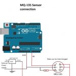
ACS758 to Arduino Connection
- Pin 1 (Vcc) → Arduino 5V
- Pin 3 (Out) → Arduino A0 (analog input)
- Pin 2 (GND) → Arduino GND
- Pin 4 and 5 → Connect in series with load, like battery or motor positive line
Note: We must use a thick wire or busbar through current terminals because high current is flowing there.
Arduino Code for Reading ACS758
Here is simple code for bidirectional 50A sensor:
const int sensorPin = A0;
float sensitivity = 0.040; // 40 mV per Amp
float offset = 2.5;        // Midpoint voltage

void setup() {
  Serial.begin(9600);
}

void loop() {
  int adcValue = analogRead(sensorPin);
  float voltage = (adcValue * 5.0) / 1023.0;
  float current = (voltage - offset) / sensitivity;
  Serial.print("Current = ");
  Serial.print(current);
  Serial.println(" A");
  delay(500);
}
So Bro, this will keep showing the real-time current in serial monitor.
Some Important Things to Note
- If we use 3.3V MCU like ESP32 then sensor output must be divided using resistors or use 3.3V version sensor.
- There may be small noise in signal, we can use RC filter or average values in code.
- Make sure wire connections are tight, or else measurement may fluctuate.
- Always use heat sink or fan if using near max current.
How to Turn ON a Relay using an Arduino when Current Exceeds the set Limit
Now I will give you the full and final Arduino code which will:
Read current from ACS758 sensor (connected to analog pin A0).
Trigger a relay ON/OFF through a transistor driver (connected to digital pin D8).
Work with bidirectional version of ACS758 (like ACS758-050B).
Show you everything clearly — which pin goes where.
Full Circuit Diagram

Let’s do it step-by-step.
Wiring Connections:
ACS758 Sensor:
| ACS758 Pin | Connect To |
|---|---|
| Vcc (Pin 1) | Arduino 5V |
| OUT (Pin 2) | Arduino A0 (Analog Input) |
| GND (Pin 3) | Arduino GND |
| Thick terminals | In series with load |
Relay Transistor Driver (using BC547):
| Component | Connect To |
|---|---|
| Arduino D8 | → 1k resistor → transistor base |
| Transistor emitter | → GND |
| Relay one side | → +12V |
| Relay other side | → transistor collector |
| 1N4007 Diode | Across relay coil (cathode to +12V, anode to collector) |
Full Arduino Code:
// === Pin Definitions ===
const int currentSensorPin = A0;    // ACS758 output connected here
const int relayControlPin = 8;      // Goes to base resistor of transistor

// === Sensor Calibration (for ACS758-050B) ===
const float zeroCurrentVoltage = 2.5;  // 2.5V when no current (center voltage)
const float sensitivity = 0.04;        // 40mV per Amp (for 50A version)

void setup() {
  Serial.begin(9600);                 // For debugging
  pinMode(relayControlPin, OUTPUT);  // Relay driver pin
  digitalWrite(relayControlPin, LOW); // Make sure relay is OFF at start
}

void loop() {
  int adcValue = analogRead(currentSensorPin);         // Read analog voltage
  float voltage = (adcValue * 5.0) / 1023.0;            // Convert to volts
  float current = (voltage - zeroCurrentVoltage) / sensitivity;  // Calc current in amps

  Serial.print("Voltage: ");
  Serial.print(voltage);
  Serial.print(" V, Current: ");
  Serial.print(current);
  Serial.println(" A");

  // === Threshold Relay Logic ===
  if (current > 10.0) {               // If current > 10 Amps
    digitalWrite(relayControlPin, HIGH);  // Turn ON relay
  } else {
    digitalWrite(relayControlPin, LOW);   // Turn OFF relay
  }

  delay(1000); // Wait 1 second before next reading
}
How It Works:
- When there is no current, then ACS758 gives 2.5V.
- When current flows forward then output voltage goes up.
- Arduino reads the voltage then converts it to current.
- If current > 10A → Arduino sends HIGH to pin D8 → transistor turns ON → relay activates.
- If current < 10A → D8 is LOW → transistor OFF → relay OFF.
Notes:
If you are using ACS758-100U (unidirectional) then base voltage will be around 0.6V and formula becomes:
current = (voltage - 0.6) / 0.02; // For 100U (20mV per amp)Arduino and the relay power both must use the single common GND.
ACS758 Sensor:
| ACS758 Pin | Connect To |
|---|---|
| Vcc (Pin 1) | Arduino 5V |
| OUT (Pin 2) | Arduino A0 (Analog Input) |
| GND (Pin 3) | Arduino GND |
| Thick terminals | In series with load |
Relay Transistor Driver (using BC547):
| Component | Connect To |
|---|---|
| Arduino D8 | → 1k resistor → transistor base |
| Transistor emitter | → GND |
| Relay one side | → +12V |
| Relay other side | → transistor collector |
| 1N4007 Diode | Across relay coil (cathode to +12V, anode to collector) |
Where and Why to Use ACS758
This IC is very good for:
- Battery charging circuits
- Solar MPPT systems
- Inverter systems
- DC motor current feedback
- Overcurrent protection
- Power monitoring
Because this IC is fully isolated, and no heat issue like shunt resistor.
Elaborate Explanation: Output Behavior of Bidirectional and Unidirectional ACS758
So when we use the ACS758 current sensor, then we must first understand what type of version we are using — whether it is bidirectional or unidirectional because the output voltage behavior is totally different in both.
Bidirectional ACS758 – How Output Works
OK, so now suppose we are using bidirectional version like ACS758LCB-050B which means it can measure both directions of current – like forward and backward or charging and discharging, or positive and negative current flow.
Now in this type, inside the IC, the output voltage is designed to stay at exactly half of the supply voltage (Vcc) when there is zero current flowing.
So if we give 5V to the Vcc pin of ACS758, then:
- When no current is flowing, then output voltage = 5V / 2 = 2.5V
This 2.5V is called the "zero current level" or quiescent voltage.
Now what happens when current starts flowing?
If the current flows in positive direction (let us say from terminal 4 to 5) then the magnetic field created is in one direction and Hall sensor detects this and increases the output voltage above 2.5V.
- Example: +10A current → output = 2.5V + (10 × sensitivity)
If current flows in negative direction (like from terminal 5 to 4), then magnetic field goes in opposite direction, so Hall sensor drops the output below 2.5V.
- Example: -10A current → output = 2.5V - (10 × sensitivity)
This way, the 2.5V works like the center point and current changes shift voltage up or down from this center.
Let us take actual example:
If sensor is ACS758LCB-050B then Sensitivity = 40 mV/A
| Current | Output Voltage |
|---|---|
| 0 A | 2.50 V |
| +10 A | 2.90 V |
| -10 A | 2.10 V |
| +25 A | 3.50 V |
| -25 A | 1.50 V |
| +50 A | 4.50 V (max) |
| -50 A | 0.50 V (min) |
So we can see that this type can show both charging and discharging or motor forward and reverse current etc. Very useful for bidirectional systems like solar charge controllers, inverters, BMS, etc.
Unidirectional ACS758 – How Output Works
Now if we are using unidirectional version like ACS758LCB-050U then this type is made for only one direction current sensing. So this can only detect 0A to max +50A, no negative current.
Now in this type, the output voltage at zero current is not at center (not 2.5V) but instead at a small base level, usually around 0.6V or 0.5V.
This small voltage is still there, even when no current is flowing. It is needed because the sensor's amplifier needs some minimum voltage to start sensing.
So in this unidirectional sensor:
- 0A current → Output = around 0.6V
- +10A → Output = 0.6V + (10 × 60mV) = 1.2V
- +50A → Output = 0.6V + (50 × 60mV) = 3.6V
Note: Sensitivity for unidirectional is usually 60 mV/A, more than bidirectional.
| Current | Output Voltage |
|---|---|
| 0 A | ~0.6 V |
| +10 A | 1.20 V |
| +25 A | 2.10 V |
| +50 A | 3.60 V |
So here, as current increases, voltage keeps increasing but only in one direction. This is perfect for applications where current flows only one way, like power supplies, LED drivers, basic DC loads.
Important Caution
- If you wrongly use bidirectional formula for unidirectional sensor or vice versa, the current value will be totally wrong.
- Always check datasheet for:
- Type: Uni or Bi
- Sensitivity (in mV/A)
- Offset voltage (0A voltage)
- Never assume that all ACS sensors work same. They look same but output system is different.
Quick Summary Table: Bidirectional vs Unidirectional ACS758
| Feature | Bidirectional Type | Unidirectional Type |
|---|---|---|
| Current Sense Range | -X A to +X A (e.g., -50A to +50A) | 0 A to +X A (e.g., 0A to 50A) |
| Zero Current Output | 2.5V (for Vcc = 5V) | ~0.6V |
| Output Direction | Goes Up & Down from center | Goes only Up from base |
| Sensitivity | 20 to 40 mV/A | 40 to 60 mV/A |
| Good For | Bi-directional systems (solar, BMS) | Single direction (LED driver, charger) |
Analog Operation with Relay Cut-off, without Arduino
Now let me explain very clearly and verbally, step-by-step, how to make a simple analog circuit using ACS758 to trigger a relay when the current goes above a certain level.
We will not use any Arduino or digital logic. We will just use ACS758, one opamp comparator, and one relay driver transistor. Everything fully analog, super simple.
Objective:
We want to turn ON a relay only when current goes above a threshold value, like say 10 amps. When current is below that, then relay stays OFF.
Parts Needed:
- 1 x ACS758 sensor module (any version you want, say 50A bidirectional)
- 1 x Opamp IC (like LM358 or LM324)
- 1 x Relay (12V or 5V depending on your supply)
- 1 x NPN transistor (like BC547 or 2N2222)
- 1 x Diode 1N4007 (for relay back EMF)
- 1 x 10k potentiometer (for setting threshold)
- Some resistors (1k, 10k), power supply
Circuit Connection – Verbal Explanation:
Step 1: ACS758 Wiring
- Pin 1 (Vcc) of ACS758 → connect to +5V regulated supply.
- Pin 3 (OUT) → this is the analog output voltage, which will change based on current.
- Pin 2 (GND) → connect to ground (0V).
- The thick terminals of ACS758 → connect in series with your load current wire.
Step 2: Opamp Comparator Setup
- Take an 741 opamp.
- Connect Pin 8 of 741 → to +5V
- Connect Pin 4 → to GND
Now do this:
- Take the ACS758 output pin (Pin 3) and connect it to non-inverting input of opamp → Pin 3
- Take a 10k preset, connect its two ends to +5V and GND.
- Take the center wiper pin of the pot and connect it to the inverting input → Pin 2 of opamp.
So now we can set the threshold voltage using this preset.
Step 3: Opamp Output to Relay Driver
- The output pin of opamp is Pin 1 (for LM358).
- Connect Pin 1 to the base of a transistor (like BC547) through a 1k resistor.
- Connect emitter of transistor to GND.
- Connect one side of relay coil to +12V, and the other side to collector of transistor.
- Put a 1N4007 diode across the relay coil, cathode to +12V, anode to collector.
Circuit Diagram

How It Works:
- When current is below threshold, then ACS758 output voltage is less than the voltage set by preset → opamp output = LOW → transistor OFF → relay OFF.
- When current goes above threshold, then ACS758 output voltage becomes greater than preset reference → opamp output goes HIGH → transistor turns ON → relay gets activated.
Example Threshold Setup:
Let us say you are using ACS758-050B (bidirectional, 40 mV/A):
- 0A → 2.5V output
- 10A → 2.5 + (10 × 0.04) = 2.9V
So if you set the pot to give 2.9V at Pin 2 of opamp then relay will turn ON only when current crosses 10A.
Extra Tip:
To avoid relay flickering near the threshold, you can connect a small capacitor (like 1uF) from transistor output to GND or add hysteresis using a 1M resistor from opamp output to non-inverting input (Pin 1 to Pin 3). That gives a little stability.
Advantages and Disadvantages
Pros:
- Safe and isolated
- Handles high current
- No contact needed with power line
- Works for both AC and DC
- Very accurate and linear
Cons:
- Little costly compared to resistor method
- Analog output may need filtering
- Needs 5V supply
- Cannot measure very low current (not sensitive below 0.5A)
Conclusion – Final Thoughts
So now we fully understood how ACS758 current sensor works. This is very powerful Hall effect IC which gives analog voltage output as per current passing through. It is safe, easy to use and perfect for Arduino or inverter projects where we need current sense.
If we want simple and robust current measurement up to 100 amps then this IC is best choice.

Questions & Answers
hello, thanks for the sharing. however, the module i bought have two output pin compared to what is stated here is only one, my output pin is labeled OU2 and OU1 respectively from the left to right, may i know which output pin should i connect for my module acs758lcb current sensor module 50a acs758lcb-050b? thanks again
Hi, I tried to find your two output module details online but I could not find any such module existing? So I am unable to provide the exact specifications of youur module.
However If your module has two outputs then you can check their outputs and see which one is generating the required output and then use that output for the current sensing….
hello, thanks for the prompt reply. I found on this website: https://qqtrading.com.my/index.php?route=product/product&product_id=2261&search=acs758lcb+current+sensor+module+50a+acs758lcb-050b, kindly refer to the image which has the label OU1 OU2, thanks.
I think they have divided the single output from the IC into two, because the IC is a single IC with a single output.
In that case you can use any one of those outputs, or check the PCB track layout and see which one is connecting with the single OUT pin of the IC.
GOOD JOB DONE.THANK YOU.