This article discusses a method through which any ready made SMPS can be converted into a variable current smps circuit using a few external jumper links.
In one of the previous articles I have explained how to make a variable voltage SMPS circuit by employing a simple shunt regulators stage, in the present hack also we employ the same circuit stage for implementing a variable current output feature.
What is SMPS
SMPS stands for Switch-Mode-Power-Supply, which uses a high frequency ferrite based switching converter for converting the AC 220V to DC. The use of a high frequency ferrite transformer makes the system highly efficient in terms of compactness, power loss, and cost.
The SMPS concept today has almost completely replaced the traditional iron core transformers and have transformed these units into a much compact, light weight and efficient power adaptor alternatives.
However since SMPS units are commonly available as fixed voltage modules achieving a preferred voltage as per the users application needs becomes quite difficult.
For example for charging a 12V battery one may need an output voltage of around 14.5V, but this value being quite odd and non-standard we may find it extremely difficult to get an SMPS rated with these specs in the market.
Although variable SMPS circuits can be found in the market, these may be costlier than the ordinary fixed voltage variants, therefore finding a method of transforming an existing fixed voltage SMPS into a variable type looks more interesting and desirable.
By investigating the concept a little I was able to find a very simple method of implementing the same, I have explained how to conduct this modification.
You will find one popular 12V 1amp SMPS circuit in my blog which actually has an in built variable voltage feature.
The Function of Opto-coupler in SMPS
In the above linked post I have explained how an opto coupler played an important role in providing the crucial constant output feature for any SMPS.
The function of the opto coupler may be understood with the following brief explanation:
The opto coupler possesses an inbuilt LED/photo-transistor circuitry, this device is integrated with the SMPS outputs stage such that when the output tends to rise above the unsafe threshold, the LED inside the opto lights up forcing the phototransistor to conduct.
The photo-transistor in turn is configured across a sensitive "shut down" point of the SMPS driver stage wherein the conduction of the photo-transistor forces the input stage to shut down.
The above condition results in the SMPS output to also instantaneously shut down, however the moment this switching initiates, it corrects and restores the output to the safe zone and the LED inside the opto deactivates which once again switches ON the input stage of the SMPS.
This operation keeps on cycling rapidly from On to OFF and vice versa ensuring a constant voltage at the output.
Adjustable Current SMPS Modification
In order to achieve a current control feature inside any SMPS we yet again seek the help of the opto coupler.
We implement a simple modification using a BC547 transistor configuration as shown below:
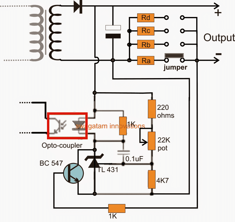
Referring to the above design we get a clear idea regarding how to modify or make a variable current SMPS driver circuit.
The opto coupler (indicated by red square) will be present by default for all SMPS modules, and assuming that the TL431 is not present then we may have to configure the entire configuration associated with opto coupler LED.
If the TL431 stage is already a part of the SMPS circuit, in that case we just have to consider integrating the BC547 stage which becomes solely responsible for the proposed current control of the circuit.
The BC547 can be seen connected with its collector/emitter across the TL431 IC's cathode/anode, and the base of BC547 can be seen connected with the output (-) of the SMPS via a group of selectable resistors Ra, Rb, Rc, Rd.
These resistors being in between the base and emitter of the BC547 transistor begin functioning like current sensors for the circuit.
These are appropriately calculated such that by shifting the jumper connection across the relevant contacts, different current limits are introduced in the line.
When the current tends to increase beyond the set threshold as determined by the values of the corresponding resistors, a potential difference is developed across the base/emitter of the BC547 which becomes sufficient to turn ON the transistor, shorting the TL431 IC between the opto LEd and ground.
The above action instantly lights up the LED of the opto, sending a "fault" signal to the input side of the SMPS via the opto's in-built photo transistor.
The condition immediately tries to execute a shut down across the output side which in turn stops the BC547 from conducting and the situation fluctuates from ON to OFF and ON rapidly ensuring that the current never exceeds the predetermined threshold.
The resistors Ra...Rd may be calculated by using the following formula:
R = 0.7/cut-of current threshold
For example if suppose we want to connect an LED at the output having a current rating of 1 amp.
We can set the value of the corresponding resistor (selected by the jumper) as:
R = 0.7/1 = 0.7 ohm
Wattage of the resistor can be simply gotten by multiplying the variants, i.e. 0.7 x 1 = 0.7 watts or simply 1 watt.
The calculated resistor ensures that the output current to the LED never crosses the 1 amp mark, thereby safeguarding the LED from damage, other values for the remaining resistors may be appropriately calculated for getting the desired variable current option in the SMPS module.
Modifying a Fixed SMPS into Variable Voltage SMPS
This following post tries to determine a method through which any SMPS could be made into a variable power supply for achieving any desired voltage level from 0 to maximum.
What is Shunt Regulator
We find that it employs a shunt regulator circuit stage for executing the variable voltage feature in the design.
Another interesting aspect is that this shunt regulator device implements the feature by regulating the input of the opto coupler of the circuit.
Now since a feedback opto coupler stage is invariably employed in all SMPS circuits, by introducing a shunt regulator one can easily transform a fixed SMPS into a variable counterpart.
In fact one can also make a variable SMPS circuit using the same principle as explained above.
You may want to learn more about what's a shunt regulator and how it works.
Procedures:
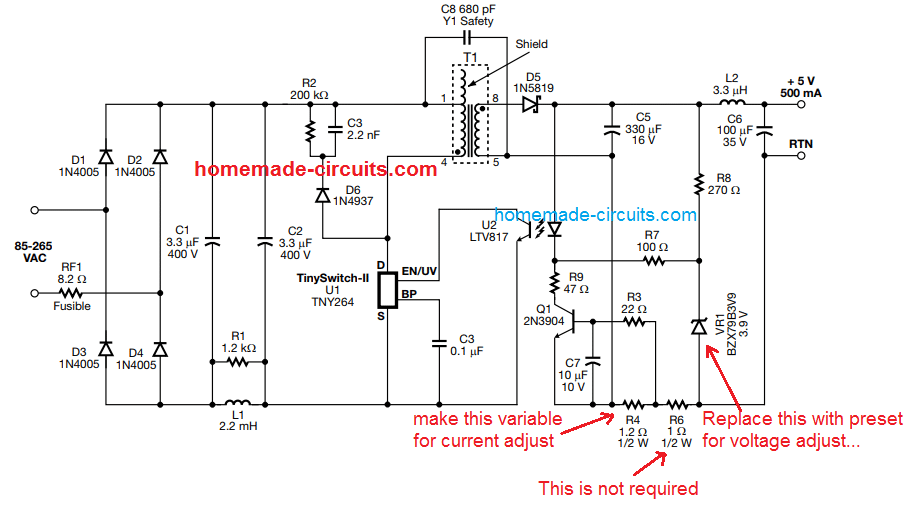
Referring to the following example circuit, we are able to find the exact location of the shunt regulator and its configuration details:
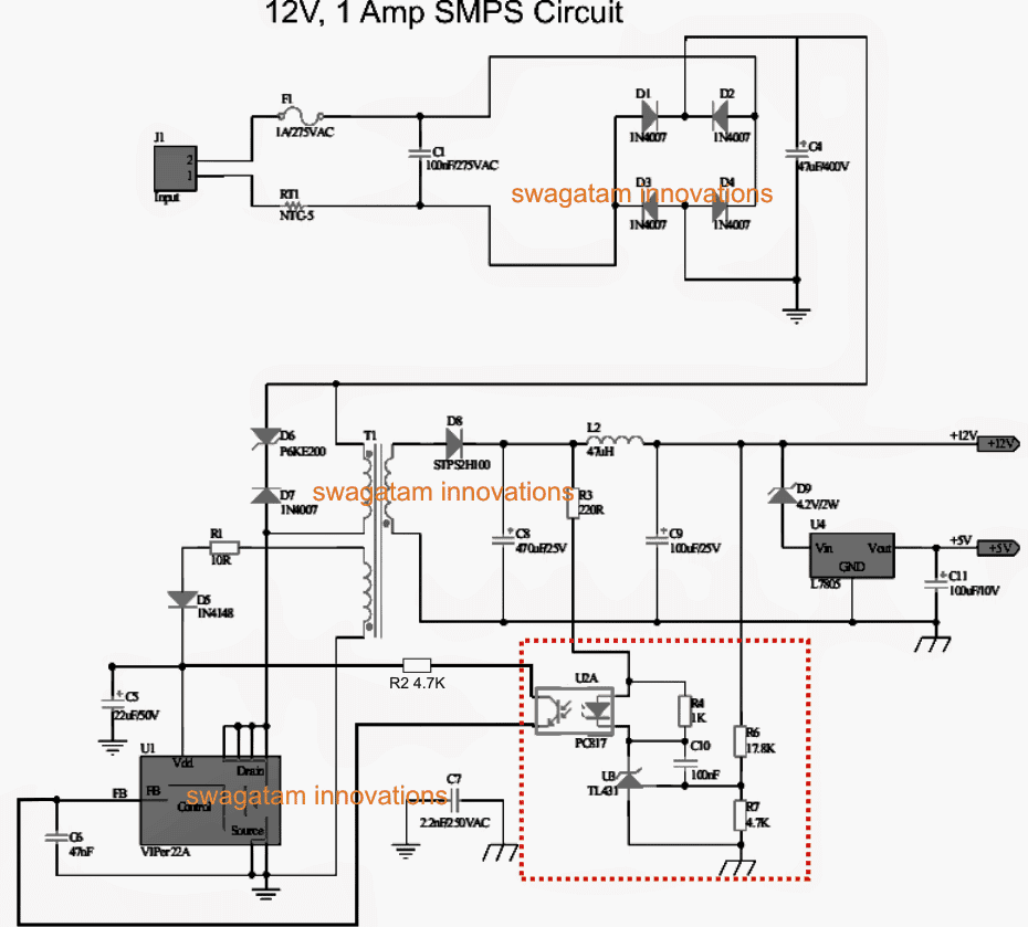
See the bottom right side of the diagram marked with red dotted lines, it shows the variable section of the circuit we are interested in. This section becomes responsible for the intended voltage regulation actions.
Here the resistor R6 can be replaced with a 22K pot for making the design variable.
Magnifying this section provides a better view of the involved details:
Identifying the Optocoupler
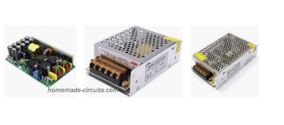
If you have a fixed voltage SMPS circuit, open it and just look out for the optocoupler in the design, it would be mostly located just around the central ferrite transformer, as may be seen in the following image:
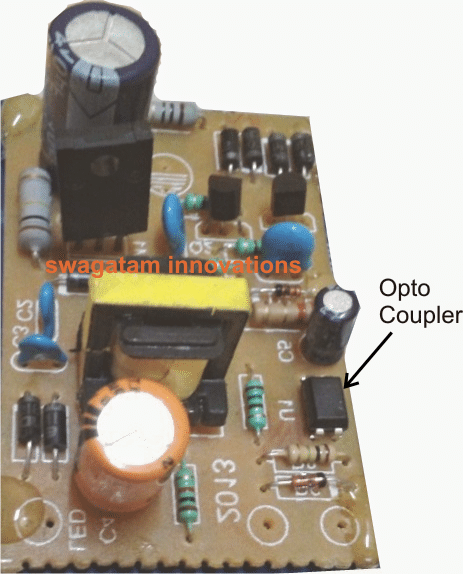
Once you have found the opto-coupler, clean up by removing all the parts associated on the output side of of the opto, meaning across the pins which may be towards the output side of the SMPS PCB.
And connect or integrate these pins of the opto with the assembled circuit using the TL431, shown in the previous diagram.
You can assemble the TL431 section on a small piece of general purpose PCB and glue it on the main SMPS board.
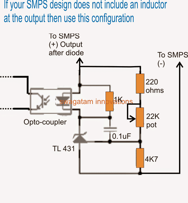
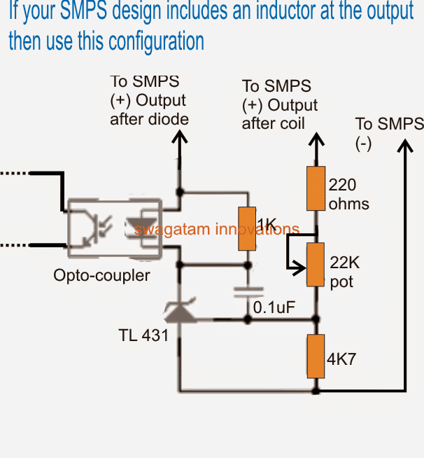
If your SMPS circuit does not have an output filter coil, you can simply short the two positives of the TL431 circuit and join the termination to the cathode of the SMPS output diode.
However suppose your SMPS already includes the TL431 circuit with the opto coupler then simply find the position of the R6 resistor and replace it with a pot (see R6 location in the first diagram above).
Don't forget to add a 220 ohms or 470 ohm resistor in series with the POT otherwise while adjusting the pot to the upper most level could instantly damage the TL431 shunt device.
That's it, now you know exactly how to convert or make a variable voltage SMPS circuit using the above explained steps.
Warning: SMPS circuits are not isolated from AC Mains on the primary side, and can be lethal to touch while in uncovered and switched ON condition.
UPDATE
The following image shows perhaps the easiest way to customize an SMPS circuit for getting a variable voltage and current features. Please see how the pots or presets needs to be configured across the opto-coupler for getting the intended results:
If you have any further doubts regarding the design or the explanation, feel free to express through your comments.
Let's Summarize
In this write up we quickly try to summarize the main points regarding how to modify any SMPS circuit through an easy hack which may help us to get a desired customized output from the unit.
What is an SMPS
SMPS stands for switch mode power supply and it's the modern and most compact/efficient way of acquiring low voltage DC from mains AC source.
However making an SMPS at home may not be as simple as making power supply units using traditional iron core transformers.
Also getting an SMPS with custom specs may not be that easy, in fact impossible if the voltage/current specs are far away from the regular values.
So does that mean we have to be satisfied with the SMPS specs which are typically set, and available in the market?
For example how do we find an SMPS having an output of say 13 volts or 14 volts or 17 volts which are definitely not the normally accepted voltage ranges?
Customizing an SMPS unit
Since making such a customized unit may not be an easy task (due to complex layouts and part configurations) it would be a lot better if we could find ways of modifying a readymade one through some simple steps.
I have studied a few standard SMPS units and hopefully cracked ways of modifying the voltages and current as per individual choices. I have explained it in details.
When you open any standard SMPS unit, you will come across the following things over the enclosed assembled card.
The populated PCB can be primarily divided into two sections by the presence of the center ferrite transformer.
The side of the transformer where the mains chord makes its entry is the input AC section while the other side from where the low voltage DC is derived is the DC section.
We are not interested in the AC section because we do not want to modify the input voltage so do not pay any attention there, moreover the AC section is POTENTIALLY VERY DANGEROUS TO TOUCH IN SWITCHED ON CONDITION, THEREFORE KEEPS YOUR HANDS OF IT WHILE TESTING.
The DC section will mainly consist of a couple of chokes, a couple of filter capacitors, a diode and a few other components.
Look for the Shunt Regulator
Search for a transistor shaped component in this section. If you find a couple of them, one will be actually a transistor, probably for limiting the output current, however the other one will be definitely THE PROGRAMMABLE SHUNT REGULATOR.
This shunt regulator is the component which fixes the feedback voltage to the AC section mosfet and in turn determines the output voltage.
This programmable shunt device is set up through a couple of resistors, changing which will instantly change the output voltage as per ones wish.
Try to locate the resistors connected with the leads of this shunt device. One of them can be simply varied for changing the output voltage as per your preferences.
Take an external resistor of any value may be a 4k7 1/4 watt, now step-wise go on connecting this resistor across the resistors which are associated with the shunt regulator device.
Check and Verify the Output
Verify the output voltage each time you do the above step.
The moment you find a change in the output voltage either becoming low or high, you might have just found the one which we are looking for.
Now through some trial and error you may find out the exact value of resistor which could be replaced in place of the particular shunt resistor.
That's it, it's as simple as that, once you do it, the output voltage would get adjusted to that particular value permanently.
But do remember to remove the zener diode if there's any at the output of the power supply before you do the above procedures.


Questions & Answers
Hello, what a great description of SMPS.
I want to modify a generic SMPS to use a potentiometer for variable current output, and not just using jumpers and lo-ohm shunt resistors as described in the article.
My SMPS has the opto coupler and TL431.
This looks doable, but can’t see how to do it.
Any help please?
Hey, thanks, glad you liked it.
For a continuous adjustment, you might need to add an opamp for that, a BJT based controller might not work effectively…
Hey
Nice place on the net, I must say 😊
Can I connect a SMPS with an ‘old’ variable (volt) power-supply with some sort of circuit so that my SMPS output voltage follows the output voltage of the ‘old’ power-supply (or other variable voltage source)?
Thank You in advance
Thank you Fuscus 😊,
The variable power supply must be able to provide an output AC or DC from 100V to 270V…
But still that won’t help the SMPS to give you a proportionately variable output.
Thank You, Swagatam, for Your quick answer 😊
I was thinking that it might be possible to design a circuit that could force the smps-output to follow the variable voltage by letting the opto-coupler in the smps compare output voltage from the variable source with the actual output voltage of the the smps?
No problem Fuscus, now i understand your idea.
Yes, that may be possible, by converting the input voltage into a proportionately changing PWM in the SMPS…
Here is an example design which you can try:
https://www.homemade-circuits.com/220v-ac-to-12v-dc-flyback-smps-circuit-using-ic-555-7555/
Thank You again, Swagatam 😊
It is really nice to read your quick answers 😊
I think I will try the circuit, You sent me.
Have a nice day 😊
/Fuscus
You are welcome Fuscus😊,
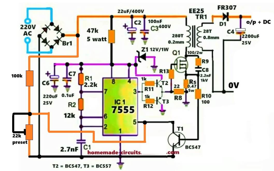
I think I forgot to give you the circuit diagram, here it is. Please try it at your convenience, and let me know if you face any issues with it:
thanks, great useful information
You are most welcome 🙂
sy punya smps 20volt sampai 50volt 3Ampere.
Sy ingin out put antara 12votl sampai 15 votl .
Smps saya ini TDK pakai TL 431 hny memakai transistor BC 541 , bgmn cara agar bisa tegangan di variabel antara 12 v sampai 25v ?
You can integrate the following circuit with the output of your SMPS:
https://www.homemade-circuits.com/0-to-50-v-adjustable-switching-power-supply-circuit-using-ic-lm2576/
Dear Swagatam.
Thank you for your posting about modifying smps-units which I have read with great interest. I may have missed it in your post, but just to make sure: If you increase the output voltage it may be nessasry to change the electrolytic capacitors in the output circuit to higher voltage ones. I modified a couple of 12V units to give about 20V which far exceeds the voltage rating of the original capacitors (16V).
Best regards, and keep up the good work.
Thank you Dear Hans,
You are right, although a fundamental improvement for the output capacitor, a very crucial one and we have to make sure we don’t forget it to do!
Hello dear Swagatam ,thanks for sharing your knowledge.
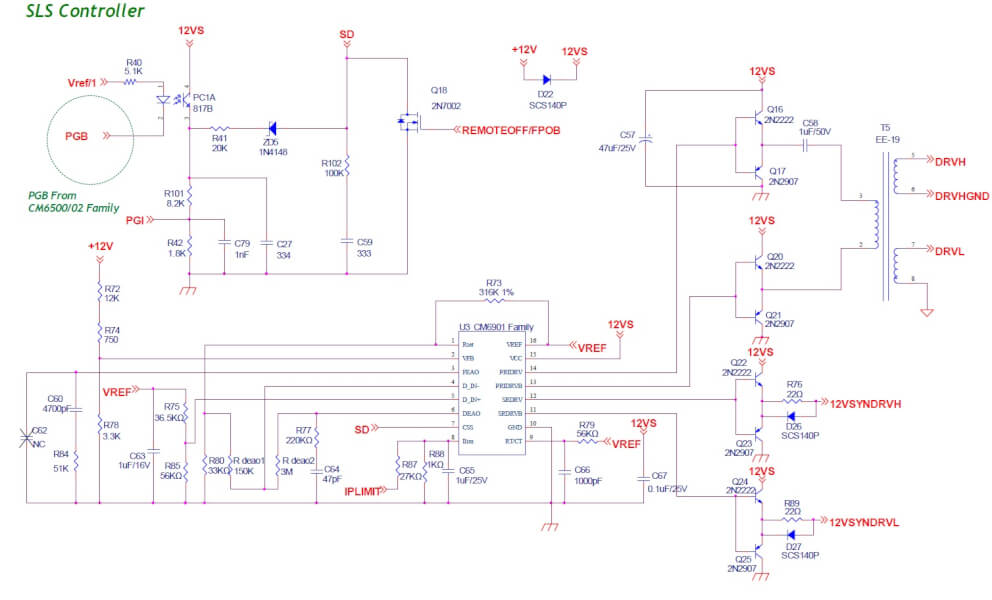
I have 12V 3.3KW SMPS following almost CM6901T6 typical application circuit.
Easy to adjust V Out with VFB (pin 2) .
But cannot adjust I Out (variable I Out).
Ilim (pin 8) just switch Off SMPS when it reaches the set value (275A but easy to modify).
I sent email to CHAMPION but no answer…
Do you think it is possible to add a trimmer to this circuit by deactivating ILIM (I grounded it) to use the voltage coming from the IPLIMIT sensor (L2/PQ512) ?
Regards
Samsara
Thank you Samsara,
Yes, it is possible to add a trimpot or a preset at ILIM, but why do you want to deactivate ILIM? Because that is the current sensing input:
Hello dear Swagatam ,thanks for quick reply.
Unfortunately ILIM (pin 8) cannot be used as variable current, because it just switch off power supply when reach 1V.
For example : 0,9V at pin 8 do nothing, power supply work without I limitation .
In PDF :
“Auto-retry Mode
During normal operation, CSS pin will be charged to 5.5V + VBE.
a)When VFB exceeds 2.93V O.V.P detect
b)VFB less than 0.5V avoid VFB short to GND.
c)ILIM exceeds 1V due to over current condition.
Output drivers are immediate set to low , and CSS begins to discharge with 0.75uA current source. When CSS pin
is below 0.9V, 7.5uA current source start charging the CSS pin. When CSS pin reaches 1V, the output drivers are
re-enable and the controller goes into soft start mode. If over current condition still exists then, the outputs are
immediately disabled, but CSS continues to charge toward 5V. When CSS reaches 5V, 7.5uA charging current is
disabled and 0.75uA current source begins to discharge the CSS, and the cycle repeat until over current condition
is removed.”
In fact, when ILIM exceeds 1V power supply is OFF , and waiting after load removed do nothing, so power supply must be switched OFF (there’s ON/OFF switch) then ON for working.
I think must use IPLIMIT signal for add it to VFB (pin 2) ,but how?
Regards
Samsara
Thank you Samsara,
I think CSS must be enabled with minimum 1V in order initiate restart once the over-current is removed…
Yes VFB can be used simultaneously used for current control, along with over voltage control….
You can add a current sensing resistor in series with the load, and add a preset parallel to this sensing resistor and then use the wiper arm of the preset to feed the feedback VFB pin.
Hello dear Swagatam.
Adding a current resistor with the load is not possible due to the huge amount of amps.
There’s already current sensor from IPLIMIT (its current from primary via a simple transformer).
For testing, I adjusted IPLIMIT resistors R66/R67 for give 0,1V when loading 1A.
I disconnected R67 from GND then connected R67 to +12V.
Then disconnected R72 from +12V then connected R72 to R66/R67 (of course, not connected to R87 ,and ILIM pin 8 connected to GND) .
Now IPLIMIT and +12V are in series.
Without load SMPS work , give +12V.
But with 1A load Vout is not stable and give 11,70V.
Worst , with 10A load it switch off SMPS… ???
Hi Samsara,
According to me using a current sensing resistor is an effective way to sense and cut-off high current thresholds.
For extreme high currents this resistor just needs to be a 3cm long iron wire maybe 4mm or 5mm thick.
Then the voltage developed across this resistor can be used to trigger a shut down process for the IC.
I meant anode not Cathode for Gmhos readings.
I am looking to obtain 12 VDC up to 450 VDC in incremental steps. I built a linear supply, with zener regulated MOSFET regulation and a step attenuator. (Actually 3 of them). Two that have steps at 12, 40, 100, 250, 300, 350, 400 and 450 VDC and one that is just a variable 0 to -100 VDC I can dial in in 1/2 volt steps. These supply the anode, screen grid and control grid of a vacuum tube. The heater voltages are from a salvaged tube tester transformer and two large filament transformers: 5 volts @ 20 amps & 6.3 volts @ 20 amps. I am using two function generators for the transconductance using the American AC mA/volt on the cathode method. I would love to make something similar using SMPS power supplies. My proof of concept used a bunch of Variacs and transformers but the mains voltage is not very stable, so I added MOSFET regulators. You helped me out with a P channel MOSFET regulator for a massive tube regulated PSU’s refernce power and I thank you profusely for it. I doubled the size of that transformer too. It acted like a fuse, and was in the same category of parts as fuses and lamps. $400 for a custom made transformer that blows out like a fuse is ridiculous. It’s sort of fused now. There is a protection circuit that initiates a timed & controlled shutdown sequence now, and it prevents improper startup sequences too. The tube PSUs work well for tube testing too. 0-1000 VDC anode 0-600 VDC screens, 0- -200 VDC bias. I can throw some PSUs in series and get up to 1600 VDC anode, 1000 VDC screens and -450 VDC grid. If I use Variacs and some old US Navy transmitter transformers increase that to 0-5000 VDC anode & screens & 0- -1600 VDC bias. Those transformers weigh about 135 kilos each. The bias supply is about the same. The large Variacs are also quite heavy.
Thanks very much Seth, for updating your feedback here, it is much appreciated.
Let me know if there’s anything you would want to know further regarding this concept…
Thanks a lot.
Have once modify my SMPS (19v 3A PC charger) by changing the output voltage feedback to get 5v
And it does output my 5v as required, but with 0 current, that can’t even power a 5v fan
And with some tiki tik sound on the transformer.
Pls, how could I solve this or have to rewind the transformer
Atiku, in that case, it is better to use an external 5V buck converter at the output of the SMPS to get the required 5V output….because modifying the SMPS internally can be complex….
Thanks you Sir
You are welcome, Atiku.
Hello, I have several SMPS blocks MEANWELL LRS-75 with fixed output 12V/6A. I tried to convert them into variable ones in order to supply and control railway models. I made appropriate modification of the voltage F/B (changing TL431 divider resistors, putting a pot etc.) but a couple of problems occurred: 1) lowering the output voltage it jumps from 2.5V directly to 0V, which is absolutely unacceptable – the output must vary smoothly from 0 to 12V ; 2) at low output the voltage is unstable and load regulation worsens significantly. I would appreciate any idea how to overcome these issues. Thanks in advance. Best regards, Emil
Hello, I will need to see the complete of your SMPS configuration to suggest my opinion. If possible please upload it here.
Nevertheless, the TL431 can be definitely configured to provide a continuously varying output voltage or to trigger a load at a specific threshold, and this threshold can be continuously varied with a pot or a preset.
You can read more about TL431 in the following article:
https://www.homemade-circuits.com/explaining-programmable-shunt-regulator/
Swagatam. You are my hero for having circuits mostly not found elsewhere and explained at the right level. On SMPS modifications, you need to state the obvious, if you raise the voltage, and the original output caps are say 10v, and you want 20volts, then they need to be upped to at least 25v, but 50v or more is also an upgrade given many caps have suspect ratings. I was also recently told those small variable resistors from say China, usually have a voltage rating of 50v or less. So if you want reliability, hang on to those big pots hardly made anymore.
Finally e-waste is on the rise, and solar panel inverter units are being thrown out, many not lasting five years. There appears to be no service manuals for them. I now have dozens of 470uF 500v high quality Rubicon or similar, making the ‘upgrading’ of old classic stereo systems possible, also valve guitar amps considered famous. But I can’t see any circuits to use the many beefy IGBT’s from these units.
Thank you so much Ethernet, for your sweet words!
I completely agree with you, if the voltage rating is increased, the relevant capacitor voltage spec will also need to upgraded accordingly.
It is always good to have a lot of spare parts in our junk box, glad you have plenty of them with you.
IGBTs are normally used in applications which involve high current switching, if you have any such requirement, please let me know I will try to figure out an appropriate IGBT based design for you.
Hello sir,
I have 12V, 2Amp SMPS.
Configuration: Cosmo C1010 opto coupler, SG684965DZ switching ic, tl431, 18k & 4.7k voltage dividers, 390Ohm bias resistor, 560ohm parallel to opto diode.
I have tried and tested to modify its out put by placing some combinations of voltage dividers (1ohm, 50k pot, 680ohm) (1k, 10k pot, 1k) etc.., every time i test its output, it’s giving steady voltage maximum 23v but fluctuating below 9v. Any help ?. Thanks in advance.
Hello Harsha,
The SMPS is trying to go into a shut down mode and therefore it is oscillating. That means the main circuit of the SMPS is regulated to supply 12 V only and this cannot be exceeded above a certain limit.
Hi sir,
Without using tl431 can we modify 24v to 36v?
Hi Kush, I don’t think that would be possible.
Hi sir
I am not using tl431 in our circuit.
For voltage regulation we are using zener.
Can we modify 24v to 36v with current reduce?
Hi Kush,
If your SMPS has a zener diode only and no TL431 then you can alter the zener diode value to increase the output voltage.
Sir its led start blinking if changed zener diode with 33v
It is detecting a high output voltage and going into cut-off mode. In that case you will have to disconnect the zener diode link with the SMPS primary side circuit.
Sir esa nahi ho sakta ki me SMPS ka transformer hi change kardu 24v 10a ke SMPS me 24v 15a ka transformer add kar sakta hu ?
That is mostly not possible. Ferrite transformer winding are built with proper calculations so they cannot be replaced with different transformers.
But you can give it a try…if by chance the winding conditions are similar then your problem may be solved.
Sir mere pass 24v 10a ka SMPS ha kya me amps ko badha sakta hu ?
Ha to kese ?
Neeraj, you can increase the current by adding more parallel wire turns in the secondary winding of the transformer. You can do the same to the primary winding also.
You will have to open the winding then rewind by adding more wires in parallel.
I have an smps source and I just want to change the current, not the voltage. What parts of the scheme should I use? I tried to use bc547, 1k resistor tied to the base and shunt resistor, but it does not work. Thanks!
Please see the last schematic and try the modifications as given. The idea is to activate the opto-coupler as soon as an over current is detected.
Everything i set up correctly and final result was 0 volt at output and 1k 1watt is heating that’s why voltage drop accure in current control circuit.
i think my smps not giving enough power transformer is heating and mosfet too i have to use another power supply which can handle power upto 100watt full system is heating up after that i figured out smps output is also flactuating in some seconds but charging is still going on so i just reduced output little bit lower so amps and heating problem solve little bit.
heating causing voltage drop and performance too ..
And thank you sir for helping peoples like me keep this good work going on I always be here for learning and asking silly questions ????
And sorry for my bad English ????
You can increase the 1K to 10K, it should still work since the pass transistor is a Darlington configuration. This circuit which I suggested is perfect and should be able to fulfill your requirement.
Let me know if you have any more further questions.