• Skip to main content
  • Skip to primary sidebar

Homemade Circuit Projects

Need circuit help? Post them in the comments! I've answered over 50,000!

Blog | Categories | About | Hire Me | Contact | Calculators-online
You are here: Home / Inverter Circuits / How to Charge a Cell Phone from a 1.5V Battery

How to Charge a Cell Phone from a 1.5V Battery

Last Updated on May 17, 2019 by Swagatam 17 Comments

In this post I have explained a very simple charging a cell phone from a 1.5v battery utilizing merely a 1.5V as the input source. The source can be any 1.5V cell rated at minimum 1000 mAH.

Table of Contents
  • Circuit Operation
    • Circuit Diagram

Circuit Operation

The circuit description is provided below, let's try to understand the working principle of the proposed cell phone charger circuit using a 1.5V source.

The circuit of a phone charger bears a simple design, with two surface-mount transistors, an inductor, diode, resistor and LED.

However, it should be noted that, one transistor acts as a controller while the other as FET. As the controller gets power from the output (5v) of the circuit, and detecting no-load; the same shuts down.

Moreover it requires very less current. Connecting the 1v5 battery, the controller initiates using less than 1v5 because of the Schottkey diode, charging the 1uF capacitor with the use of FET and flyback effect of the inductor; thus producing high voltage.

With the voltage of output set to 5v, the controller goes in ‘Off’ state, and the only load managed by the 1uF is the controller. As the voltage falls across the capacitor, the controller turns on in bursts, thereby charging the 1uF to 5v.

The method of charging a cell phone from a 1.5v battery is very cheap and can be made at as low as $3, and it also comes with 4 adapter leads.

Submitted By: Dhrubajyoti Biswas

Circuit Diagram
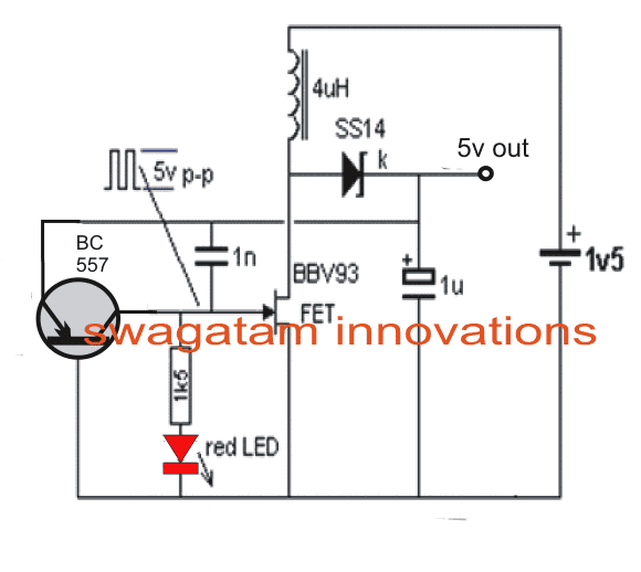
charge cell phone with 1.5V battery

You'll also like:

  • 500 watt500 Watt Inverter Circuit with Battery Charger
  • How to Build a 400 Watt High Power Inverter Circuit
  • Convert a Square Wave Inverter into a Sine Wave Inverter
  • Troubleshooting Inverter Output Voltage Drop Issue

Filed Under: Inverter Circuits Tagged With: Battery, Cell, Charge, Phone

About Swagatam

I am an electronics engineer and doing practical hands-on work from more than 15 years now. Building real circuits, testing them and also making PCB layouts by myself. I really love doing all these things like inventing something new, designing electronics and also helping other people like hobby guys who want to make their own cool circuits at home.

And that is the main reason why I started this website homemade-circuits.com, to share different types of circuit ideas..

If you are having any kind of doubt or question related to circuits then just write down your question in the comment box below, I am like always checking, so I guarantee I will reply you for sure!


Previous Post: « 2 Best Current Limiter Circuits Explained
Next Post: Bicycle LED Light Circuit Using a Single 1.5V Cell »

Reader Interactions

Questions & Answers

Total Posts: 17
Newest Oldest
Unknown
October 18, 2016 • 10 years ago #45681

HI Can you show bulding this Circuit step by step and with the Pic of the components

Reply
Sherwin Baptista
July 3, 2015 • 11 years ago #31949

Dear,
I prepared this circuit after understanding its concept and it worked well, but with some modifications done;
1. i used 3v as input supply. i also added a 330u 25v cap at input rail.
2. i made the circuit keeping the 1uf cap temporarily disconnected, i got a no-load voltage of 19v(18.93 on dmm)
3. i used 2 2n7000 fets parallel in circuit.
4. i used toroidal inductor with 10t of normal solid wire.
5. i removed led and resistor, connected to o/p rail.
6. i used a 10u35v cap at o/p in place of 1u.
7. i added a zener and resistor network to give 5v.
now i got 5.13 volts.
8. finally, i added a 10u35v tantalum and the whole circuit is now complete.
Thanks, sir for this basic circuit design,
Your circuits are really helpful.
Now i can call it my own power bank circuit.

Regards

Reply
SwagatamAdmin
July 3, 2015 • 11 years ago #31957

Dear Sherwin, that's very impressive, thanks for updating the info….and if it's possible you can send the pics of your circuit for publishing, ….only if it's extremely convenient

Reply
Sherwin Baptista
June 20, 2015 • 11 years ago #31657

Dear,
1. Using a duracell, what could be the efficiency of the circuit?
2. Could i use a toroidal core for the inductor since i have them on hand? Is the inductance value crucial here?
3. What changes should i make if i use 3v as input supply?
Thanks.

Reply
SwagatamAdmin
June 21, 2015 • 11 years ago #31663

Dear, the above circuit has not been tested by me, so I can't suggest much about it… I would rather recommend you to try the following circuit instead:

https://www.homemade-circuits.com/2012/10/1-watt-led-driver-using-joule-thief.html

Reply
Sherwin Baptista
January 30, 2015 • 11 years ago #28531

Hello dear,
what type of diode is ss14?
plese help.

Reply
SwagatamAdmin
February 1, 2015 • 11 years ago #28538

hello Sherwin, it's a fast recovery, zero drop type of diode

Reply
won's work
August 14, 2013 • 13 years ago #14331

Hi Dear swagatham,
can I use BAT54 Schottkey diode or any other in place of SS14?

Reply
SwagatamAdmin
August 16, 2013 • 13 years ago #14404

The pleasures's all mine:)

Reply
won's work
August 16, 2013 • 13 years ago #14380

OK Dear I'll,thank you very much! I really like your works and your kindness to give an answer for everyone's question!
Good job…!

Reply
SwagatamAdmin
August 15, 2013 • 13 years ago #14353

Dear Won,

Actually I have not tested this circuit so not very sure, you can try the part and check how it functions

Reply
Unknown
August 3, 2013 • 13 years ago #14017

BBV93 BF245A equivalent

Reply
SwagatamAdmin
August 4, 2013 • 13 years ago #14035

both are n-channel fets, so might work as a replacement

Reply
Aditya Soni
July 25, 2013 • 13 years ago #13757

Dear
Can you give some more detail about inductor for correct purchase?
Thank you

Reply
SwagatamAdmin
July 25, 2013 • 13 years ago #13783

It has to be hand made, it might not be available in the market.

Reply
SwagatamAdmin
July 14, 2013 • 13 years ago #13382

both are n-channel fets, so it might work

Reply
Unknown
July 14, 2013 • 13 years ago #13374

BBV93 BF245A equivalent

Reply

Need Help? Please Leave a Comment! We value your input—Kindly keep it relevant to the above topic! Cancel reply

Your email address will not be published. Required fields are marked *

Primary Sidebar


My Youtube Channel

Circuit Simulator

circuit simulator image


Subscribe to get New Circuits in your Email


Categories

  • Arduino Projects (95)
  • Audio and Amplifier Projects (134)
  • Automation Projects (18)
  • Automobile Electronics (103)
  • Battery Charger Circuits (88)
  • Datasheets and Components (109)
  • Electronics Theory (149)
  • Energy from Magnets and Earth (40)
  • Games and Sports Projects (11)
  • Grid and 3-Phase (20)
  • Health related Projects (27)
  • Home Electrical Circuits (13)
  • Indicator Circuits (16)
  • Inverter Circuits (99)
  • Lamps and Lights (162)
  • Meters and Testers (72)
  • Mini Projects (28)
  • Motor Controller (68)
  • Oscillator Circuits (28)
  • Pets and Pests (15)
  • Power Supply Circuits (91)
  • Remote Control Circuits (50)
  • Security and Alarm (65)
  • Sensors and Detectors (107)
  • SMPS and Converters (45)
  • Solar Controller Circuits (60)
  • Temperature Controllers (43)
  • Timer and Delay Relay (50)
  • Voltage Control and Protection (44)
  • Water Controller (37)
  • Wireless Circuits (31)


Other Links

  • Privacy Policy
  • Cookie Policy
  • Disclaimer
  • Copyright
  • Videos
  • Sitemap

People also Search

555 Circuits | 741 Circuits | LM324 Circuits | LM338 Circuits | 4017 Circuits | Ultrasonic Projects | SMPS Projects | Christmas Projects | MOSFETs | Radio Circuits | Laser Circuits | PIR Projects |


Recent Comments

  • Swagatam on 3 Tested 220V High and Low Voltage Cut OFF Circuits Using IC LM324 and Transistors
  • ENGR BRIGHT on 3 Tested 220V High and Low Voltage Cut OFF Circuits Using IC LM324 and Transistors
  • Swagatam on IC LM393 Complete Datasheet with Circuit Diagram
  • Norman D Kelley on IC LM393 Complete Datasheet with Circuit Diagram
  • Swagatam on Simple Capacitive Discharge Ignition (CDI) Circuit

Social Profiles

  • Twitter
  • YouTube
  • Instagram
  • Pinterest
  • My Facebook-Page
  • Stack Exchange
  • Linkedin

© 2026 · Swagatam Innovations