• Skip to main content
  • Skip to primary sidebar

Homemade Circuit Projects

Need circuit help? Post them in the comments! I've answered over 50,000!

Blog | Categories | About | Hire Me | Contact | Calculators-online
You are here: Home / Lamps and Lights / Sound Activated LED Lamp Circuit

Sound Activated LED Lamp Circuit

Last Updated on June 8, 2026 by Swagatam 5 Comments

A highly sensitive sound activated LED lamp circuit can be built using just a few transistors and resistors.

Table of Contents
  • What does the Circuit do?
  • Circuit Description
    • Parts List
  • LED Configuration

The circuit is actually a high gain MIC amplifier circuit which amplifies the external sound hitting the MIC. The amplified signal is then used to momentarily illuminate a bunch of LEDs.

What does the Circuit do?

Basically, this sound activated LED lamp works in the following manner:

When a sound hits the MIC, the MIC converts it into tiny electrical pulses. These tiny pulses are then amplified into larger voltage and current by a couple of transistor stages.

This amplified voltage and current is then applied to a set of LEDs. The LEDs thus respond and switch ON each time sound vibration is detected by the MIC.

The circuit has a delay OFF feature which ensures that the LEDs remain ON for a second or two even after the sound is no longer available on the MIC.

Circuit Description
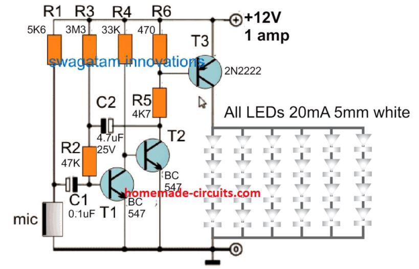
Sound Activated LED Lamp Circuit

The diagram above mistakenly shows the PNP BJT as 2N2222, please ignore it and make sure to replace it with 2N2907 BJT...

Parts List

  • Resistors are all 1/4 watt 5% CFR
  • 5.6K = 1
  • 47K = 1
  • 3.3M = 1
  • 33K = 1
  • 4.7K = 1
  • 470 ohms = 1
  • Capacitors
  • 0.1uF Ceramic Disc = 1
  • 4.7uF/25V electrolytic = 1
  • Transistors
  • BC547 = 2
  • 2N2222 = 1
  • LEDs 3.3 V, 20 mA = 24
  • MIC, electret type = 1

Referring to the above circuit diagram, the working of the sound activated LED lamp can be understood with the following points.

Transistor T1, capacitor C1, resistors R1, R2, R3 together form a simple electret MIC preamplifier circuit.

The basic function of this stage is to boost the minute electrical pulses from the MIC into a relatively larger voltage pulses.

Transistor T2 and T3 along with the resistors R4, R5, R6 are configured to work like a power amplifier.

The job of this power amplifier is to boost the preamplified pulses at the collector of T1 into significantly larger voltage and current output.

This amplified voltage and current is finally used to drive the set of LEDs, connected at the collector of transistor T3.

Resistor R3, together with capacitor C2 are used to add a delay OFF feature on the LEDs. This ensures that the LEDs remain illuminated for some seconds even after the sound vibrations cease to exist on the MIC.

C2 value can be increased or decreased to correspondingly increase or decrease the delay OFF timing of the LED switch OFF period.

The sensitivity of the circuit can be adjusted by adjusting the value of the R1 resistor. Higher values will mean lower sensitivity and vice versa.

LED Configuration

In the proposed circuit, 4 LEDs are used in series on each of the strings, and 6 of these strings are connected in parallel.

The LED strings can be seen without a current limiting resistor. This is because the 12V DC supply is presumed to be constant here. Considering each LED is rated at 3.3 V, 4 in series constitutes 3.3 x 4 = 13.2 V, which is lower than 12V, so no limiting resistor is required.

If your 12V DC is not constant, then you can add a current limiting resistor with each string, using the following formula:

R = (Supply DC - LED total forward voltage) / LED Current

R = (Supply DC - 13.2) / 0.02

The 0.02 represents the LED current of 20 mA, for the LED strings.

You'll also like:

  • Flashlight Circuit with Long Backup and High Efficiency
  • LED2Btube252C2BMOVSimple LED Tubelight Circuit
  • How to Connect Car LED Downlight: Circuit Diagram
  • 100wattleddrivercircuit100 Watt LED Constant Current Driver Circuit Diagram

Filed Under: Lamps and Lights Tagged With: Activated, Lamp, LED, Sound

About Swagatam

I am an electronics engineer and doing practical hands-on work from more than 15 years now. Building real circuits, testing them and also making PCB layouts by myself. I really love doing all these things like inventing something new, designing electronics and also helping other people like hobby guys who want to make their own cool circuits at home.

And that is the main reason why I started this website homemade-circuits.com, to share different types of circuit ideas..

If you are having any kind of doubt or question related to circuits then just write down your question in the comment box below, I am like always checking, so I guarantee I will reply you for sure!

Previous Post: « High Efficiency Li-Ion LED Driver Circuits Explained
Next Post: Design your own Sine Wave Inverter Circuit from the Scratch [Tutorial] »

Reader Interactions

Questions & Answers

Total Posts: 5
Newest Oldest
rosario
April 11, 2026 • 6 months ago #204776

Good morning, engineer. I saw the schematic. It’s a nice project. I just have a question. In the schematic, the 2N2222 transistor T3 is represented as a PNP, but if you look at the datasheets online, it appears to be an NPN. Thanks

Reply
SwagatamAdmin
April 11, 2026 • 6 months ago #204779

Good Evening Rosario, and thanks for pointing out the typo in the diagram.
Actually I wanted to write 2N2907, but mistakenly wrote 2N2222.
I would request you to ignore the 2N2222 print and replace it with 2N2907….

Reply
Rosario
April 11, 2026 • 6 months ago #204781

thanks

Reply
rosario
April 12, 2026 • 6 months ago #204800

Good morning again, Engineer.
Capacitor C1 is listed as electrolytic in the diagram, but then in the components list it’s listed as ceramic. Which is the correct one?
Thanks

Reply
SwagatamAdmin
April 12, 2026 • 6 months ago #204824

Sorry for the confusion, ceramic is correct, and moreover 0.1uF is mostly available in ceramic.

Reply

Need Help? Please Leave a Comment! We value your input—Kindly keep it relevant to the above topic! Cancel reply

Your email address will not be published. Required fields are marked *

Primary Sidebar

My YouTube Channel

Circuit Simulator: Draw and Simulate Schematics

circuit simulator image

Categories

  • Arduino Projects (95)
  • Audio and Amplifier Projects (134)
  • Automation Projects (18)
  • Automobile Electronics (104)
  • Battery Charger Circuits (90)
  • Datasheets and Components (109)
  • Electronics Theory (151)
  • Energy from Magnets and Earth (43)
  • Games and Sports Projects (11)
  • Grid and 3-Phase (20)
  • Health related Projects (27)
  • Home Electrical Circuits (13)
  • Indicator Circuits (16)
  • Inverter Circuits (98)
  • Lamps and Lights (161)
  • Meters and Testers (72)
  • Mini Projects (28)
  • Motor Controller (68)
  • Oscillator Circuits (30)
  • Pets and Pests (15)
  • Power Supply Circuits (91)
  • Remote Control Circuits (50)
  • Security and Alarm (65)
  • Sensors and Detectors (107)
  • SMPS and Converters (46)
  • Solar Controller Circuits (62)
  • Temperature Controllers (44)
  • Timer and Delay Relay (51)
  • Voltage Control and Protection (44)
  • Water Controller (37)
  • Wireless Circuits (31)

Subscribe to get New Circuits in your Email

Other Links

  • Privacy Policy
  • Cookie Policy
  • Disclaimer
  • Copyright
  • Videos
  • Sitemap

People also Search

555 Circuits | 741 Circuits | LM324 Circuits | LM338 Circuits | 4017 Circuits | Ultrasonic Projects | SMPS Projects | Christmas Projects | MOSFETs | Radio Circuits | Laser Circuits | PIR Projects |

Recent Comments

  • Swagatam on 24V to 12V DC Converter Circuit [using Switching Regulator]
  • Swagatam on Automatic Battery Full Cut-Off Latching Circuit with Trickle Charging
  • Ramin on Automatic Battery Full Cut-Off Latching Circuit with Trickle Charging
  • Joss on 24V to 12V DC Converter Circuit [using Switching Regulator]
  • Swagatam on Simple Capacitive Discharge Ignition (CDI) Circuit

Social Profiles

  • Twitter
  • YouTube
  • Instagram
  • Pinterest
  • My Facebook-Page
  • Stack Exchange
  • Linkedin

Calculators

  • ZVS Induction Heater + Tank Calculator Tool
  • Zener Diode Calculator
  • Wire Current and Thickness Calculator (Ampacity Calculator)
  • Voltage Divider Calculator
  • Transistor Base Resistor Calculator
  • Transistor Astable Multivibrator Calculator
  • TL431 Calculator
  • Solar Panel, Inverter, Battery Calculator
  • Ferrite Core Air Gap Calculator Tool
  • Parallel MOSFET Calculator Tool: How to Connect MOSFETs in Parallel Safely
  • LC Resonance Calculator for EV Battery Charger Circuits
  • LED String Series Resistor Calculator
  • PFC (Power Factor Correction) Calculator Tool: 3kW
  • Passive Power Factor Correction (PFC) Calculator
  • LM567 IC Calculator Tool
  • SMPS Flyback Boost Converter Calculator
  • Shunt Resistor Calculator for Ammeters
  • SCR and Triac Gate Resistor Calculator
  • Battery Back up Time Calculator
  • Boost Converter Calculator (Non-Isolated)
  • Bootstrap Capacitor Calculator
  • Buck Converter Calculator
  • Buck-Boost Converter Calculator
  • Capacitance Reactance Calculator
  • DCM Flyback Transformer & Wire Gauge Wire Size Calculator Tool
  • Filter Capacitor Calculator
  • IC 4047 Calculator (Frequency and PWM)
  • IC 4060 Calculator
  • IC 555 Astable Calculator
  • IC 555 Monostable Calculator
  • IC SG3525, SG3524 Calculator
  • Inductance Calculator
  • Induction Heater Inductor and Resonant Frequency Calculator
  • Induction Heater Work Coil Calculator
  • Inverter LC Filter Calculator
  • LC Resonance Calculator
  • LED Current Calculator
  • LM317, LM338, LM396 Calculator
  • NAND/NOT Gate RC Values Calculator
  • NOT, NAND Gate Frequency Calculator
  • Notch Filter Calculator Tool
  • Ohm’s Law Calculator
  • Phase Angle Phase Shift Calculator
  • Power Factor (PF) Calculator
  • RC Filter Calculator
  • Reactance Calculator
  • Sine Table Calculator for SPWM Arduino Code
  • Small Signal Transistor(BJT) and Diode Quick Datasheet
  • SMPS Calculator for Toroidal Ferrite Transformers
  • SMPS Flyback Transformer Calculator – Design by Target Duty Cycle
  • TL431 Calculator
  • Op-Amp Hysteresis Resistor Calculator

© 2026 · Swagatam Innovations