As its name suggests, this simple vibration sensor circuit using piezo transducer allows for the detection of vibrations to which its sensor is subjected.
Unlike superficial pressure sensors whose resistance varies depending on the force they are subjected to, the transducer used here is only sensitive to variations in pressure exerted on its sensitive face.
The 27 mm piezo transducer which is used for this vibration sensor circuit is shown in the following image.
How the Circuit Works
The following figure reveals the diagram of our simple vibration sensor circuit using piezo transducer.
The sensor used is a piezoelectric blade. The application of a force to this transducer causes a deformation which results in the appearance of electrical charges on the opposite faces.

This phenomenon is visible on an oscilloscope and is represented on our board by a series of impulses at the ends of resistor R1.
This voltage is then sent through capacitor C3 to the amplifier built around transistors T1 and T2. The polarization of the whole system is ensured by the voltage divider R1 and R5.
Resistance R7 is decoupled by capacitor C5, which gives transistor T1 a significant gain, while transistor T2, which is connected in a common emitter configuration, allows for a low output impedance.
Resistors R2 and R3, on the one hand, and adjustable resistor Aj1 on the other hand, constitute the feedback network.
The gain of the amplifier is expressed by the formula G = Aj1 + R3 / R2. The attentive reader will have noticed the presence of capacitor C4, which prevents any continuous feedback.
The amplifier output drives the two flip-flops contained in a 4013 package.
Flip Flop Working
Consider flip-flop A on the diagram: a positive, albeit brief, pulse on its input will cause the output Q1 to go high, which will be maintained after the pulse disappears.
The return to the reset state can only be achieved by pressing the push button BP.
This operating mode is of the bistable type. The flip-flop B works a little differently: when the Q2 output is high, the charging of capacitor C1 through resistor R10 and adjustable Aj2 begins.
As soon as the voltage on pin 10 of IC2 exceeds half the supply voltage, the Q2 output switches to the low logic level, which is the monostable mode. The output pulse has a duration of 70 to 75 ms depending on the setting of Aj2.
The unipolar inverter, labeled INV on the diagram, allows the choice of either mode of operation.
It drives the base of transistor T3, which is configured as an open-collector, allowing for very flexible use of the circuit. It is possible to connect a relay to the collector of T3.
It is also possible to drive a logic board via T3. It should not be forgotten that, in such a case, the transistor behaves like a logic inverter.
For reliable operation of the circuit, it is imperative to stay below the maximum values of T3, whose main characteristics are as follows:
VCEO = 50V, IC max. = 600mA,
P max. = 800 mW, (T° = 25°).
The power supply of the prototype is provided by a simple 78L12 regulator.
The circuit will be powered by a voltage of at least 15V (maximum 35V) which must be perfectly filtered but not necessarily stabilized.
The idle consumption is a few milliamperes.
Construction
The implementation of the printed circuit board presents no particular difficulty and all usual reproduction methods can be used.
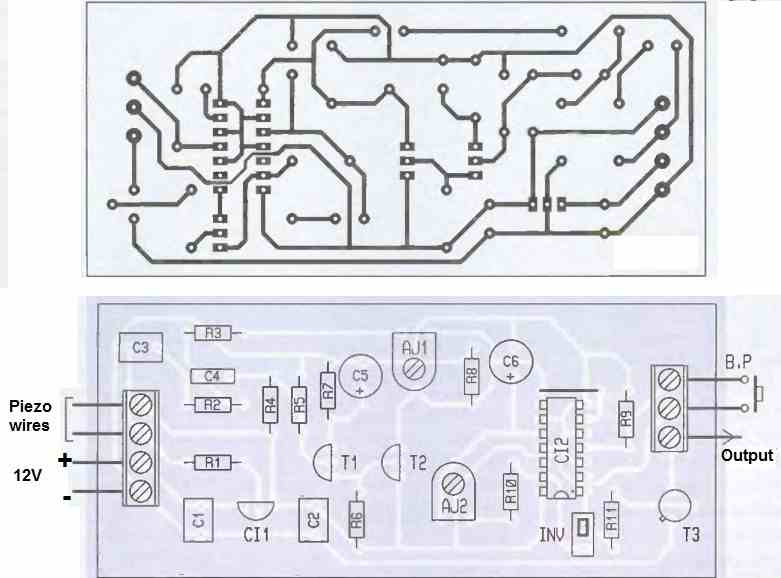
The 4013 IC will be installed on a socket, while the piezoelectric sensor will be connected to the input terminal via two flexible wires.
The adjustable resistor Aj1 allows adjusting the sensitivity of the circuit, with the median position generally being suitable.
Applications of this Vibration Sensor Circuit
A piezo transducer vibration sensor circuit with a flip flop relay can have several applications, including:
Intruder detection: This type of circuit can be used in security systems to detect intruders. When the piezo transducer detects a vibration or shock, it triggers the flip flop relay, which can then activate an alarm or notify security personnel.
Machine monitoring: This type of circuit can be used to monitor machines and equipment. When the piezo transducer detects a vibration or shock, it triggers ON the flip flop relay. The switched ON relay can then be used to turn ON a shutdown the system to prevent further damage to the equipment.
Monitoring of structures: This kind of circuit may be used to keep tabs on the condition of buildings and bridges. The flip flop relay is activated when the piezo transducer senses a vibration or shock. The relay can then turn on a warning system to inform engineers or maintenance staff.
Seismic monitoring: This type of circuit can also be used in seismic monitoring. When the piezo transducer detects a seismic event, it triggers the flip flop relay, which can then activate a data acquisition system to record the event.
Another Simple Vibration Sensor Circuit using 8 Ohm Loudspeaker as the Sensor
The circuit described below is a simple vibration sensor circuit that uses a small 8 ohm speaker as the vibration sensor.
The circuit is designed to detect vibrations or mechanical movements and trigger a relay to activate an external load (such as a motor, lamp, or buzzer).

Let's go through the working of the circuit step by step:
- Vibration Sensor (Speaker): The small 8 ohm speaker, labeled as SP1, is used as the vibration sensor. When the speaker experiences vibrations or mechanical movements, its coil generates a small voltage proportional to the vibration amplitude. This voltage is then amplified and processed through the subsequent transistor stages.
- Transistor T1: Transistor T1 is an NPN BC317 transistor. The base of T1 is connected to the speaker (SP1) through a coupling capacitor C1. The purpose of C1 is to block the DC component and allow only the AC signals (vibrations) to pass. Resistor R1 (1M) is connected across the base and collector of T1 to provide a biasing point for T1.
- Transistor T2: The amplified signal from T1's collector is fed to the base of T2, another NPN BC317 transistor, via a coupling capacitor C2 (0.1uF). Similar to T1, T2 also has a 1M resistor (R2) connected between its base and collector for biasing purposes. Additionally, the emitter of T2 is connected to ground through a 2.2K preset resistor, which allows fine-tuning of the sensitivity of the circuit.
- Capacitor C4: Capacitor C4 (10uF) is connected between the emitter of T2 and ground. It acts as a filter capacitor, smoothing out the amplified signal and blocking any DC component that might have passed through the circuit.
- Transistor T3 and Diode D1: The filtered signal from T2's emitter is fed to the base of T3, which is another NPN BC317 transistor. The collector of T3 is connected to the positive supply (+12V) through resistor R5 (47K). The base of T3 is connected to ground through a reverse-biased diode D1 (OA85). This diode D1 acts as a voltage reference and stabilizes the base voltage of T3.
- Transistor T4 and Relay: The collector of T3 is connected to the base of T4, which is a PNP 2N2907 transistor. When T3 conducts (due to the amplified and filtered signal from the vibrations), it turns on T4. The relay coil is connected between the +12V positive supply and the emitter of T4. When T4 conducts, current flows through the relay coil, activating the relay. The relay can then be used to control an external load, such as a motor or a lamp.
Overall, when vibrations are detected by the small 8 ohm speaker (vibration sensor), the vibrations are amplified and processed through the transistor stages until T3 is activated.
T3's activation then triggers T4, which, in turn, activates the relay, allowing the external load to be controlled based on the detected vibrations.
The sensitivity of the circuit can be adjusted using the 2.2K preset resistor connected to the emitter of T2.
Another Simple Vibration Sensor Circuit using IC 4001
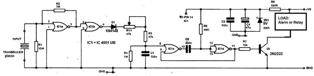
With reference to the circuit schematic up above, the circuit operates as follows.
The sensor is a piezo-ceramic transducer, which has the advantages of being compact, durable, and extremely affordable.
When the transducer is activated by the vibrations from the surface it is connected to, it produces a little signal.
Since IC1a is being utilized as an analog amplifier, it is a rather unique application of a digital gate. It is crucial to use the UB version of the 4001, as the buffered version will not function as an analogue amplifier.
The signal is rectified after being amplified, and it is then sent to a basic RC network (R3, R4, RV1, and C1).
The sensitivity of this network may be changed by varying the time constant of the network (by tweaking RV1), and this has shown to be considerably more successful than attempting to change the amplifier's gain.
The monostabie consisting of IC1c, IC1d, C2, and as is activated when a signal of adequate amplitude and duration is recognized (when the voltage on C1 exceeds the threshold of lC1c), driving the output transistor.
To make adjusting the sensitivity easier, an LED that will blink when the circuit is triggered can be attached in parallel to the output.


Questions & Answers
good eve sir.. can you help me make a vibration sensor using a comparator for Arduino sir
Hello Khan,
sorry, my knowledge regrading Arduino is not good, therefore solving Arduino related subjects can be difficult for me.