In this post I have explained the making of 3 simple yet effective smart laser alarm protection circuit using the IC 555, for securing a specified restricted zone from human interventions. The idea was requested by Mr. Collins.
Circuit Objectives and Requirements
- I just want to tell you what an amazing passion and dedication to electronics you have and thank you for helping others like me. My name is Collin from south Africa.
- We have a huge problem of safety here.
- There are countless number of robberies and house break inns its so unreal. I was hoping you can help me with regards to a circuit for a very cost effective and reliable product.
- I have built a laser tripwire alarm using a 555 IC timer but the circuit design lacks a lot of features.
- I need something that as soon as an intruder enters my property I will be alerted before they even get a chance to try and get into my home.
- The circuit needs the following: Once alarm is activated it needs to sound for a few minutes and then go off
- and arm again automatically. Don't want it ringing for hours in end if I am not at home to reset it.
- It should not be triggered by pets or flying debris in the yard.
- Easy alignment of the sensors. The laser alarm works OK but its very difficult to set the pointer on the LDR that keeps moving off. Any tips if we are going than route?
- It doesn't have to be a laser system I am open to whatever you think will solve my problem.
- Thanks a lot for everything and feel free to add whatever you think I missed out with regards to all the features.
1) The Design
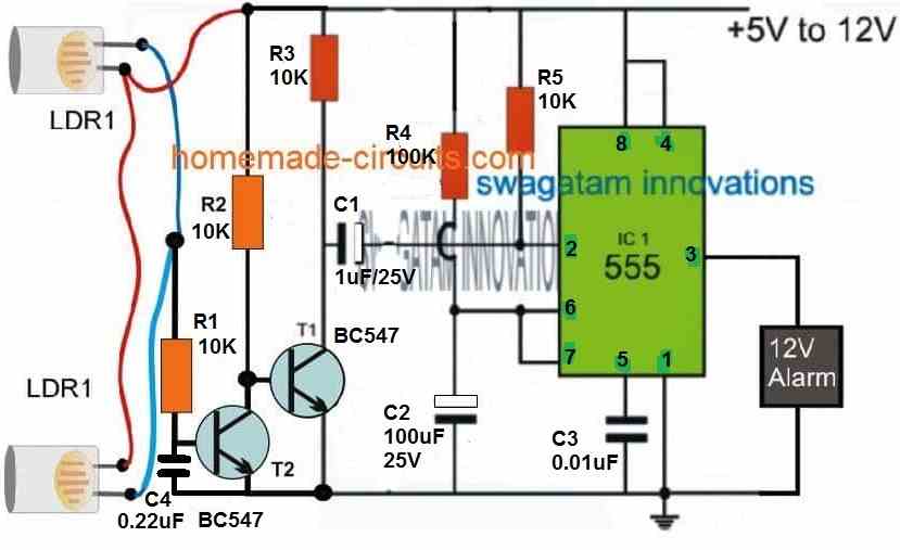
Parts List
- R1, R2, R3, R5 = 10 K
- R4 = 100 K
- C1 = 1 uF / 25 V
- C2 = 100 uF / 25 V
- C3 = 0.01 uF
- C4 = 0.22 uF
- IC = ANY 555 VARIANT
- T1, T2 = BC547
- ALARM = 12V, 200mA PIEZO ALARM.
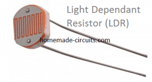
- LDR = any standard
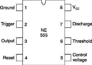
IC 555Pinouts
Circuit Operation
The proposed smart yet simple laser alarm circuit using IC 555 can be witnessed in the following image, the functioning can be understood with the following points:
1) The IC 555 is configured in its basic monostable mode.
2) Pin#2, which is the trigger input of the IC can be seen connected with the emitter of a PNP BJT via a blocking capacitor C2.
3) We can also notice a couple of parallel LDRs secured within opaque pipes and their leads hooked up with the base of the PNP BJT, such that as long as the LDRs remain illuminated together through the laser light focus, the BJT remains deactivated.
This happens because in the presence of laser light the LDR's combined resistance drops to around 30K, which keeps the base of the PNP more positive than the ground bias from R2.
4) The inclusion of two LDR ensures a fool proof alarm set-up such that only a human presence is able to interrupt the LDRs, while these remain unaffected by other smaller irrelevant intruders such as animals, birds etc.
The two LDRs could be placed at a distance of around 2 feet so that only taller objects such as a human being gets detected.
5) Therefore whenever an interruption in the laser beam is detected, the LDRs go through a sudden rise in their resistances causing T2 to switch ON, which in turn triggers pin#2 of the IC via C1.
6) This prompts the IC 555 to activate its pin#3, which finally activates the connected alarm unit.
7) Since the IC 555 is configured in its monostable mode, the pin#3 remains activated only for a period determined by the RC network at pin#6 and pin#7 of the IC, or by R3,C2.
These timing components can be appropriately calculated using the IC 555 calculator software for accomplishing the desired length of time for which the alarm may remain switched ON.
How to Set Up the Laser Transmitter Units
The laser transmitter devices could be installed near the LDRs itself and focused back to the LDRs using mirror reflectors as shown below:
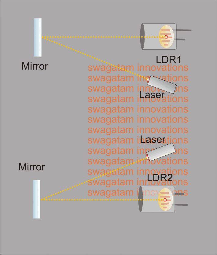
The installing of the laser devices near the LDRs allows the entire unit to be installed inside a single enclosure and also allows the lasers to be powered from the circuit itself.
This also facilitates securing the lasers and the LDR units firmly and accurately so that both the counterparts are unable to move or deviate from their positions even in an event of a mechanical shock or other vibrational interferences.
The mirrors could be positioned at some specified distance, exactly opposite to the laser installation , making sure that the laser beams intersect the restricted zone and the presence of a possible intrusion is detected without fail.
This concludes the making of the proposed IC 555 based smart laser alarm protection circuit, if you have any doubts please feel free to put them forth in the below given comments box.
Video Test Results
Using BJTs for Reducing Current Consumption
The above design can be further enhanced to work with lower standby current, and also with a battery backup during of power failures, through the following upgraded schematic:
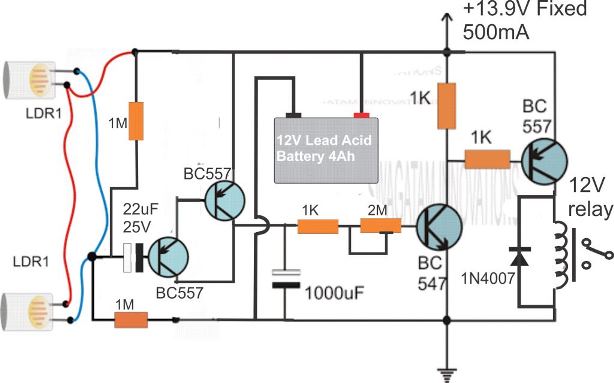
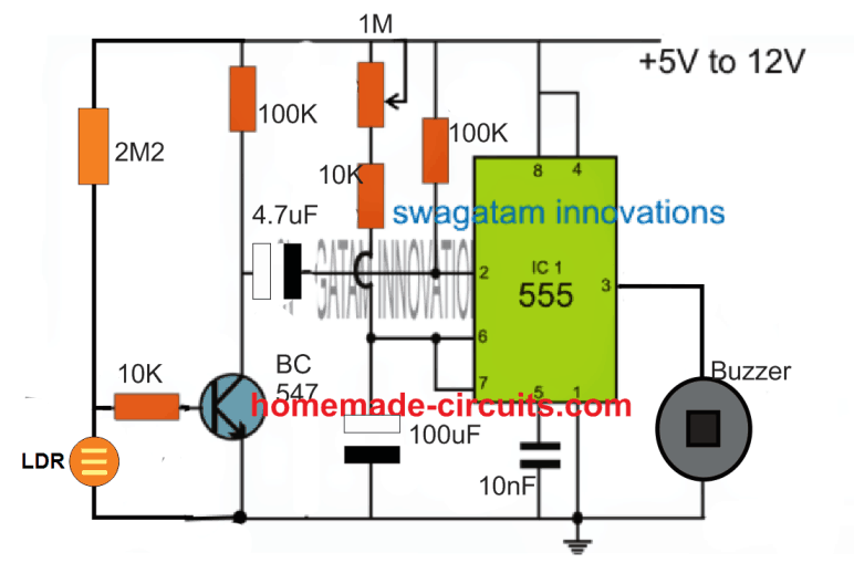
Laser Security using Single LDR
If you intend to simplify the implementation for a single LDR operation, in that case the following concept can be tried:
555 Laser Alarm Circuit with Continuous Alarm
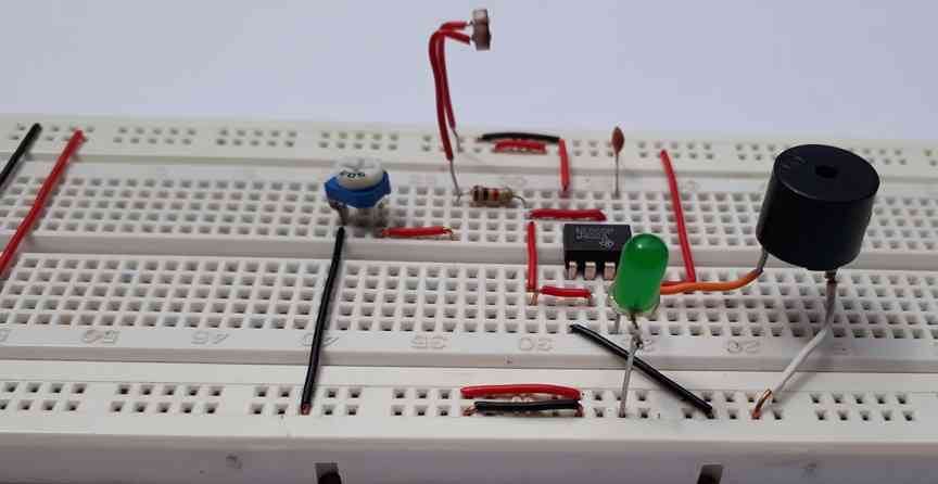
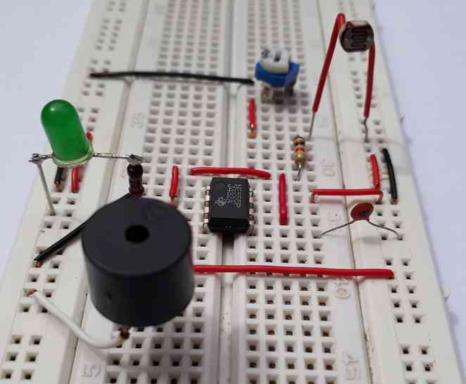
The previous alarm circuit was simplified by Mr. Ali and the whole design along with the video was contributed to this website.
We were fortunate enough to receive a video demonstration and some captivating pictures of this project from Mr. Ali.
Witnessing the system in action was truly remarkable, and we couldn't wait to share it with our readers.
We would like to express our heartfelt appreciation to Mr. Ali for not only creating this incredible IC 555 based laser alarm system but also for allowing us to showcase it on our website.
His dedication, knowledge, and passion for electronics are evident in this project, and we are grateful for the opportunity to share it with our audience.
2) Laser Alarm Circuit for Protecting Field Crops against Animals
The second idea explains another simple laser alarm circuit which can be installed in farms and fields for detecting all possible intrusions, either by a human or an animal and alarming this to the owner, and ensuring an effective protection to the crops against such intrusions. The idea was required by Mr. Mohammed and Mr. Daniel.
Circuit Request#1
Congratulations for all amazing work please give me any circuit for agricultural fields, need to protect the crops from uninvited guests like animals i want to achieve an Active infrared barrier [laser] circuit with distance range of 100 meter or above.
Circuit Request#2
sir please my grandfather is an orange farmer and he is having a problem with thief's so he ask me to do something that to protect the farm or anything that can alert him when any thief's or any person try to take away any thing from the farm so i decided to install a CCTV camera,so i need a circuit without a camera or if you can help me out sir i have said this but you can create something that can help me out thank you hope to hear from you soon
Circuit Operation
The Design
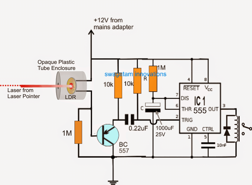
The proposed laser alarm circuit for protecting crops from animals and intruders can be seen in the figure above.
The idea appears extremely straightforward, and employs an IC 555 based monostable multivibrator stage and an LDR detector.
As shown in the design, the laser beam is generated through a laser pointer circuit held at some parallel point across the field fence which requires to be protected.
Since a laser beam has the property of focusing over a given point undistorted and on a straight line, regardless of the distance, the focus in this application is adjusted over an LDR across a specified distance, as indicated in the diagram.
The LDR is enclosed inside a light proof box with a tiny hole which allows only the laser beam to enter while obstructing most of the ambient light around.
As long as the laser beam is held focused over the the LDR, the resistance of the LDR is enabled at a minimum level which could be around 10K to 50K approximately depending on the particular LDR specs.
The low resistance from the LDR ensures a high potential at the base of the associated BC557 transistor rendering it inactive. This in turn keeps the pin#2 of the IC555 monostable at a high potential and the output of the IC at logic zero, so that the relay is held switched OFF.
Now in an even when an intruder (a human or animal) makes an attempt to cross the protected line of fence, cuts or obstructs the laser beam, which instantly causes the LDR resistance to increase and trigger the BC557 device via the 1M resistor.
The BC557 responds to this and conducts grounding pin#2 of the IC and activating the monostable action.
The above procedure forces the pin#3 of the IC to go high and switch ON the relay, the relay contacts possibly being connected with an alarm, sounds the alarm, alerting the field owner regarding the intrusion.
The alarm continues to sound for some moment of time depending on the values of R and C, whose values are directly proportional to the length of the alarm switch ON period.
The above discussed laser alarm circuit can be installed across all the corners of field for ensuring maximum and all round protection for the valuable crops and for ensuring a peaceful sleep to the field owner.
3) Laser Beam Security Alarm Circuit
We have often seen laser alarm system as an integral part of security solution especially for a location which deserves hi-level security.
The Circuit Concept
Right from a museum preserving priceless historical possession; to a safety bank vault; and even in thriller flicks where the protagonist is seen on and often tied in the ray of red light beams, while trying to reach a safe vault; one is well acquainted with the usage of laser light beams.
In fact it is also considered as a security device even in household today to ward off burglary or theft.A laser beam is not a simple beam, but has the efficacy to respond when faced a distraction.
This means that if the light ray gets interrupted with any objects, the photodiode receives resistance which in turn activates an alarm.
The laser alarm system is an economical option when it comes to consumption of power, as the receiver needs power supply less than 10 mA on average.
Setting up a laser alarm system is relatively easier as the laser and the receiver can be setup in one box, on a single power input.
Below is a circuit design diagram which illustrates the flow of a laser alarm system.
How it Works
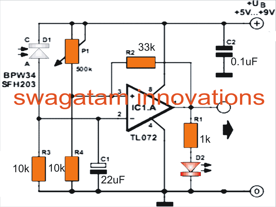
Referring to circuit diagram it is seen that a TL072 op-amp (IC1.A) is configured as a voltage comparator, placed in between the adjustable voltage driver P1/R4 and the light-dependent voltage which consists of photodiode D1 and R3 – a fixed resistor.
As the laser beam receives an interruption from a foreign agent, the beam is cut-off causing the voltage on comparator pin 2 to drop below pin 3.
This instantly enables the output of the op amp to swing to positive voltage supply and enable an alarm situation.
As the laser alarm can detect interruption from any element, so the alarm needs to be set in a more sophisticated fashion, so that it is able to bypass accidental interrupts from elements, like an insect.
This is accomplished as the Resistor R2 provides a level of hysteresis, thereby prevent oscillation when two comparator input voltage rests in almost equal state. Much faster response can be achieved by reducing the value of C1 to 1 µF.
How to Set up the Alarm
A laser beam system is easier to setup, either as a single or a separate entity.
If a single box is maintained to setup the alarm, then it is to be made sure that the photodiode can’t have direct contact with the laser beam.
Assembling the components and the circuit in a breadboard, it should be mounted in a black box having a hole.
A black drinking straw should pass through the hole to enable light flow from the direction of the laser beam to enter. Setting up the system properly makes the laser beam act even with direct sunlight, as it cannot affect the operation of the photodiode.
Article Written and Submitted by Mr. Dhrubajyoti Biswas
The following Circuit was Requested by one of the dedicated member:
l require a circuit to manipulate high-bright LEDs applied as replacement for candles on a wreath at the top of a high altar of a church.
Connecting wires or cables to this is simply not practicable, therefore I would like to have a method to switch it on and off, along with extended battery-life.
Additionally, could I make use of a pulse circuit to prevent the lights from slowly depleting the battery ?
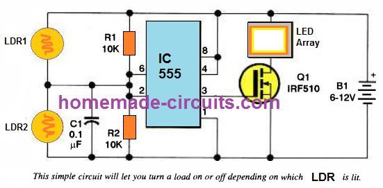
Consider the circuit shown below, driven by a 6 volt rechargeable battery. The load may include LEDs along with resistors or amoureux lamps; you may possibly have a 22 excellent candlestick light effect by operating 12V volt lamps on 6 volts.
How the Circuit Works
Switch the lights on / off by focusing the laser lamp on one or the other LDRs or photocells. In the "off" condition, lower than 1 mA current is pulled from the battery.
The circuit makes use of the hysteresis (latching) characteristic of the LM555 IC, however, it is advised to employ a CMOS model of the chip (LMC555, TLC555, or 7555) to save maximum power.
Depending on the focused photocell, if the input is under 1/3 of the battery supply, the output activates.
Similarly, when the input is over 2/3 of the supply voltage, the output switches off.
During periods the input is in the middle of these states, the output of the IC continues to be in whichever state it had been previously in.
Therefore, if both photocells or the LDRs are held with the identical amount of laser pointer light no matter what the situation might be the load or the LEDs stays unchanged, on or off.
Using High Sensitivity Op amp
Sometimes an application necessitates the use of a sensor with a greater level of sensitivity. This may be accomplished by connecting an operational amplifier to the phototransistor detector in series.
An NE5534 low-noise op-amp is utilized to enhance the gain in the design below. Lasers may be used in a number of security applications thanks to the high-sensitivity relay circuit.
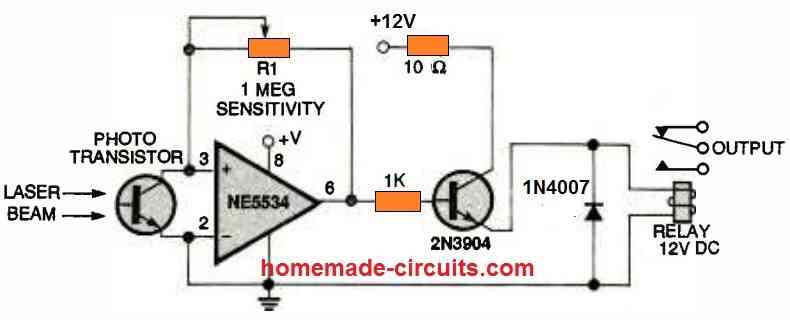
Unmonitored chambers could also be "watched" for suspicious smokes, which could indicate a fire.
Point the laser, either wholly or partly, at the high-gain relay, and set the sensitivity setting, R1, to just enable the triggering of the relay contacts.
Adjust back the preset just slightly enough to allow the relay to reopen. If smoke enters the path between the beam and the detector, it causes the relay to energize and activate the alarm.



Questions & Answers
"Smart Laser Alarm Protection Circuit using IC 555"
Sir, what can be the distance between the laser illuminator and mirror in the subject circuit.
Debasis, it will depend on how far the laser is able to travel and reflect back on the LDR without losing the required intensity..as long as it is able to implement this, it will work regardless of the distance…
It is a wonderfull website!!!!
thank you!!
Im the 1 of followers of you Mr swagatam majumdar. I like your circuit diagram.
I am glad you liked my circuits, thanks for visiting my site!! and keep up the good work
Mr swagatam I want to know the value of R3,C2,T1. Thank you.
it's 100K, 100uF/25V and BC557
sir
can u give me a simple circuit for charging 12v 7.2ah battery
NVD, you can connect the battery to a 14V/1Amp DC source and allow it to charge for 12 hours and then remove it….
thank u sir
Can you give me a fluorescent lamp electronic choke design for 36 and 40 watts . Input of 230 v 50 hz supply
you can try the following design
https://www.homemade-circuits.com/2015/11/120v-220v-electronic-ballast-circuit.html
Hai sir i am one of the follower in your blog,Can u give homemade led street light drawing.
Hi Muthukumar, you can try the following circuit
https://www.homemade-circuits.com/2016/12/simple-solar-led-street-light-system.html
Hi sir, i am from india and very much need of undermentioned circuit. Kindly help me.
After selecting 4 or 16 position in a selection knob , and pressing of push button , first 4 or 16 LEDs out of 32 should glow one by one then stop, again after push of push button 5 to 9 LEDs should glow with 1 sec gap. As it is required to teach my students and I have only mechanical background, i could not make it.please help me.
Hi Subramanyam, first I would suggest you to make the last circuit from the article which is mentioned below…and succeed making the 18 LEDs run in sequence, once you make this I will instruct you how to proceed further…
https://www.homemade-circuits.com/2011/12/how-to-make-18-led-light-chaser-circuit.html
sir, i made the above said circuit.kindly guide me to get desired result as said earlier
Subhramayam, what kind of sequencing are you getting, I am sure it's one led at a time, do you need this kind of sequencing or do you want the subsequent LEds to latch and glow constantly as the sequence proceeds?
for the second option you may have employ small SCRs at the 49017 outputs so that the LED illumination can get latched while sequencing?
after this you will need selector switches for selecting the desired sequence lengths
i mistakenly mentioned 49017…actually i meant 4017
Thanks for such a lightening reply. After selecting 4 or 16 position in a selection knob , and pressing of push button , first 4 or 16 LEDs out of 32 should glow one by one then stop, again after push of push button 5 to 9 LEDs should glow with 1 sec gap.
that means each subsequent LED must stays illuminated while they sequence..you will have to employ SCRs at the outputs for acheiving this
In above circuit all leds of first ic glow, the leds of second ic strts glowing ,but leds of first ic also simultaneously glowing, which is not required, kindly solve my problem
no that shouldn't happen? LED sequencing is supposed to start from the first pin of one IC and go on sequencing one after the other until the 18th LED on the last pinout of the second IC is reached, after this the sequence must revert to the initial pinout of the first IC and the cycle must go on repeating in the same way…please first diagnose and correct the fault in your design
Hi im just about to build this circuit for my back yard security, what ohm LDR do i need , havnt done electronics for 15 years im a little rusty! thanks for your time
paul
Hi, you can use any LDR whose resistance is able to drop to approximately 50K in ambient light (not direct light), and rises to infinity in darkness.
Hi sir can u give me idea to build revolving search light ,
Sidhesh, do you want it using a motor or without a motor through chasing LED simulation?
What is the value of R3
and C2
use the first software from this link to calculate it
https://circuitcalculators.blogspot.in/2017/10/ic-555-calculator.html
dear sir
i want to make mid night lamp which should be on 12 mid night and off at morning 4 o clock. timer or LDR circuits not effective for exact timings (while power off or bad light conditions) therefore i want use a digital clock for time input . please set instructions
Dear Jayanth, you can try the following concept and modify according to your particular needs:
https://www.homemade-circuits.com/making-programmable-timer-circuit-using/
hi . i’m still new on this . and i don’t know how to use the ic 555 calculator software . can you tell me what kind of value of R3 and C2 can use ?
You can try 100K and 22uF/25V..if the delay is not sufficient for the alarm, you can keep increasing them until you find it OK!
admin . did you have the formula to calculate the value of R3 and C2 ? other than use ic 555 calculator software.
yes, here’s the formula:
Time Out Delay (secs) = 1.1 * R1 * C1
thank you admin
admin . may i ask what is the safety of this circuit need ?
for safety use only 12V as the supply, and use a small buzzer at the output, for high power buzzer you may have to use a transistor driver at pin#3 of the IC
sir, actually I already try to install the circuit like the circuit you show . but the sensor is not working . when i connect the power supply the buzzer make a sound . can you guard me sir until my circuit is work ? i need to send my project in this week . please…
Hi Nurul, yes I’ll guide you until you are are able to complete this project, first tell me how many LDRs are you using, a single or two?
2 LDRs for 2 doors
In the above diagram both the LDRs needs to be blocked for the action, how do you wish to operate your system? If you wish the alarm to sound if any one of the LDRs are blocked, then the LDR wiring will need to be in series, and the transistor configuration will also change.
I still can’t imagine it . Can you draw the circuit ??
how do you want the LDRs to sense and function, when both are obstructed together, or each one independently and separately? meaning if any one LDR is blocked the alarm will be ON.
i want the LDRs to sense separately.
each one independently and separately
I’ll show you how to wire the LDR and then you can check it…
okey . i will waiting for it .
I have updated the diagram at the end of the post, please check it and make it exactly as shown…it will work as required by you.