I have already discussed one programmable timer circuit in this blog earlier, the circuit involves the IC 4060 for generating the basic oscillations which is further used for generating the required time intervals, however this cannot be synchronized with an external clock.
The following circuit was requested by Mr.Amit, here the concept makes use of a clock for acquiring the required base timing oscillations and therefore is able to get synchronized with external clocks or watches.
The above procedure of using simple oscillator module for acquiring the oscillations may look quite impressive, but it accompanies a serious disadvantage.
Using an External Clock for Synchronizing Time
The above type of timers cannot be synchronized with a clock and therefore are never accurate.
The article explained here utilizes a clock's second's pulses for acquiring the basic triggering oscillations for the different sections of the corresponding circuit stages which are divided into minutes, hours etc.
These outputs are suitably configured with a set reset latch for obtaining the required programmable timer application needs.
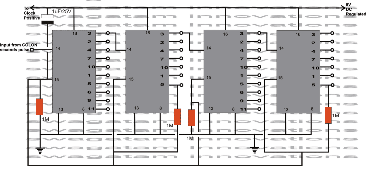
As shown in the figure the circuit basically incorporates many 4017 ICs for dividing the source seconds pulses into minutes and hours.
How it Works
Each IC 4017 consists of 10 output ports which become high and low sequentially in response to the inputs applied at its pin #14.
It means if a pulse of one second duration or 1Hz is applied at the input, the Pulse will become of 10 seconds duration at pin #3 of the IC.
The first IC from left is applied with the seconds pulses derived from a regular digital clock.
As explained above, it's pin#3 now generates 10 seconds of time interval, meaning it goes high after every 10 seconds.
This pin#3 is next connected to the input of the second 4017 IC, which again does the same, increases the time interval *10, that is it generates 10*10 = 100 seconds time, however since its pin number 5 is connected with pin#15, this IC generates 60 seconds time duration at its pin#3.
This 60 sec time interval is further applied to the input of the next 4017 IC, which now in the same way transforms this input into a period of 60*10 = 10 minutes.
The above 10 min time interval is again applied to the input of the next 4017 IC producing an output of 10*6 = 60 minutes. that is equal to 1 hour at its pin #3.
The above procedure may be increased to any number of time interval outputs just by adding more and more 4017 ICs in the array.
Now interestingly, the timing generated at the respective IC's pin outs are all in accordance to the main input acquired from the digital clock's seconds pulse, therefore are perfectly co-ordinated with the clock timing.
If you are interested to achieve a programmable feature from the above set up, you just need to appropriately calculate, assess and integrate the relevant pin outs from the corresponding ICs to the SET Resest Latch circuit input trigger terminals, as I have explained below:
Using a Set/Reset Latch
The set reset latch circuit shown in the diagram is actually nothing but a simple latching set up, which can be used to activate a relay through one of the inputs (set) and reset it back to deactivate the relay via another input trigger.
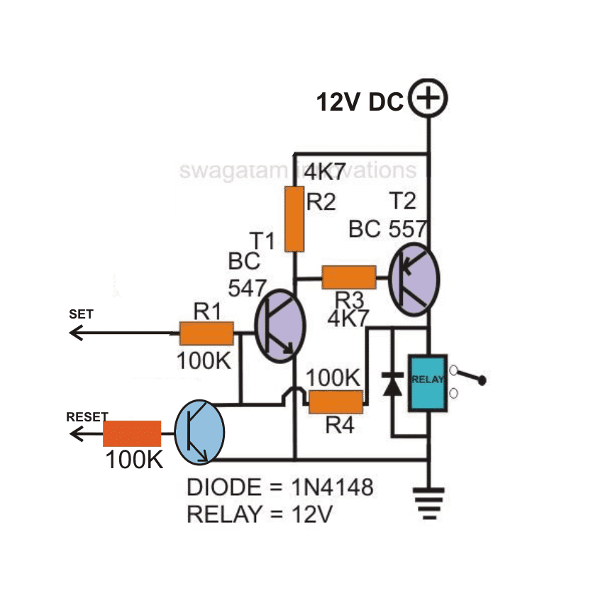
The two input triggers are separate and may be individually acquired from the above explained IC 4017 pin outs. How you would like to achieve a particular set of triggering action as per your needs will solely depend how you analyze the above set up and configure the respective pin outs with the set reset latch.
The relay associated with the set reset latch will eventually be responsible for activating and deactivating a particular load discretely as per the assigned timing inputs from the 4017 ICs.


Questions & Answers
Thanks Swagatam! I think I am following your reasoning. When the circuit is first powered, all pin #3’s are positive, so output of the fourth CD4017 will sound the alarm (which I will control the length of time sounded with a one shot circuit). After 10 minutes the fourth CD4017 will switch and pin#3 will be low and pin #2 will be high. After 60 minutes the fourth CD4017 pin#3 will be high again. This is exactly what I wanted. You are amazing! Thanks!
Thanks Norman, Glad I could help, wish you all the best!
Yes, I meant pin 11 of the first cd4017 connected to pin 14 of the second cd4017 for the divide by 10 and pin 1 of the second cd4017 connected to pin 14 of the third cd4017 for the divide by 6. Of course pin 8, pin13 and pin 15 on the first cd4017 grounded and pin 5 connected to pin 15 and pin 8, pin 13 grounded on the second cd4017. Sorry for the mind block!
As you pointed out, using pin11 to trigger the next IC may create a malfunctioning in the timing outputs, therefore the above set up looks OK to me, unless of course there’s no triggering of pin14 at power switching ON, after pin15 has been reset. I don’t think that might happen since pin14 requires a subsequent low and high clocks to trigger, so a continuous initial high after reset may not cause any triggering of the ICs.
Hi Swagatam,
I am questioning the above circuit. Don’t we have to take the output from pin 11 of the first 4017 to pin 3 of the second 4017 and take the output from pin 1 (with pin 5 connected to pin 15) of the second 4017 to get one minute with a 1 Hz input to the first 4017. I am trying to make a hourly alarm similar to a Koo Koo clock. I am using a CD4060 with a 32.768K Hz oscillator to produce a I Hz clock signal. I then take the I HZ single to pin 3 of the first CD4017. I then take the output at pin 11 of that CD4017 and feed it into pin 3 of the second CD4017 and take the output from pin 1 of that CD4017 to get one minute. I repeat the previous to get 1 hour. Maybe, I am overthinking this, but it seems to me that the timing will be off because when pin 11 energizes it triggers the pin 3 of the next CD4017 which gives a shorter time because pin 11 did not use up its complete time. If pin 3 were triggered by a falling edge, then it would be more correct. The 6 stage is correct as the reset is set from pin 5 to pin 15 which allows pin 1 (the sixth division) to complete. Are my assumptions correct? Do you have a solution around this problem? Thanks for your help!
Hi Norman, Are you referring to pin 11 to pin 14? because connecting pin 11 with pin 3 will yield nothing.
Sir.. I don't really fully understand this circuit but can I use it as a 30 second timer?and if yes How?
jason, for 30 seconds delay you can try the following circuit, the above is far too complicated:
https://www.homemade-circuits.com/2013/10/simple-adjustable-industrial-timer.html