A simple cell phone charger with timer circuit is presented in the following article, which could be used for charging a given Mobile phone for a specified predetermined length of time. The idea was requested by Mr. Saad.
Circuit Objectives and Requirements
- Could you design me this charger circuit ? Input 230V 60 Hz, and the output 3 USB port for charging Smartphones.
- What I need in this circuit is a Timer (Three sets of time), 30 mins, 60 mins and 120 mins.
- So I connect my phone to any of the three usb port and press (on/off) switch then the time start for example 60 mins then the power cut off.
- Hope you understand my request.
Circuit Diagram
Circuit Operation
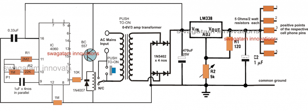
The proposed cellphone charger circuit with timer can be seen in the above figure, the design primarily comprises of an IC 4060 timer stage and a DC to DC multi cell phone charger stage.
The cell phone charger section is a standard LM338 based charger circuit, wherein the output is bifurcated into 5 individual charging outputs facilitating charging 5nos individual cellphones. From these outputs 3 channels could be utilized for the intended 3 cell phone charging, at a rate of 1500mAH each. The series resistors may be accordingly calculated using Ohms law, as given below
R = V/I = 5/1.5 = 3.33 ohms, 10 watts each
R2 in the LM338 circuit must be appropriately adjusted to achieve around 5V across the output terminals or across C2 terminals.
The timer stage is made up of the IC 4060 whose pinouts are also configured in its standard timer/counter mode.
P1 may be adjusted to get a delay time of around 120 minutes on pin#3, which would allow pin#2 to produce a delay of 60 minutes, and pin#1 a delay of 30 minutes.
Initially when power is applied across the indicated mains input terminals, the cellphone charger circuit with timer does not respond and stays deactivated.
However, the moment the given push button is pressed, causes the N/O side of the relay to get connected with the other unconnected mains wire.
This momentarily connects the AC mains with the transformer leads, which in turn powers the rectifier stage enabling a momentary DC supply input for the IC 4060 timer stage.
This momentary supply to the IC 4060 stage activates the counting of the timer, and simultaneously produces an initial zero potential at the base of the relay driver BC557 transistor, switching ON the relay from N/C to N./O points.
As soon as this happens, the relay contacts now take-over the push-to-ON switch connections and allows the AC to flow through these contacts into the transformer primary.
This ensures that, now even if the push button is released, the circuit is able to get latched into the powered position enabling the LM338 to begin charging the attached cell phones and the timer IC 4060 to count the stipulated amount of time via the pot P1.
As soon as the counting of the IC 4060 gets elapsed, pin#3 (pin#1/2 whichever is selected) turns high, switching of the BC557 and the reverting relay contacts from N/O to N/C.
This action instantly switches OFF and disconnects the mains AC from the transformer, deactivating the whole process and bringing the whole system into its original standby position.
This cellphone charger timer circuit could be yet again initiated simply by pressing the push button for the next charging cycle.
Time Delay for the IC 4060 can be calculated using the formula:
f(osc) = 1 / 2.3 x Rt x Ct
where Rt = R2 +P1 (in Ohms)
Ct = C1 (in Farads)
Parts List
Resistors, All 1/4 watt 5%
2M2 = 1
22K - 1
10K = 1
1M = 1
120 ohms = 1
1M pot= 1
5K pot = 1
Capacitors
1uF/50V non-polar = 4
0.33uF = 1
470uF/25V = 1
1uF/25V electrolytic = 1
Diodes, 1N4007 = 5
Transistor, BC557 = 1
IC, LM338 = 1
Relay,12V/400 ohm = 1
Push button = 1
Transformer = 0-12V/5 amp
Output resistors as per the given formula


Questions & Answers
Dear Can u please show me 16pin Receptible footprint or pad connection with CC1 & CC2 & data pin bcz when i cross check in 16 Pin there are many types of footprint. All symbol is almost same with pin connection, but when i tried to select pcb footprint it has internal change in A5 ,,B5,,B8 ETC. so which is real. bcz when today i check my PD with MOBILE with my circuit it also not start fast charging.
Nitesh, yes, 16-pin USB-C connector symbol look same, but inside pad mapping can be different. Specially:
A5 = CC1
B5 = CC2
A6 = D+, B6 = D+
A7 = D-, B7 = D-
A4 = VBUS, B4 = VBUS
A1/B1, A12/B12 = GND
Now some connector footprints only connect 1 side (like A-side), and other footprints do full mirror (both A and B). So if your footprint not matching or some CC pin not routed then PD handshake might not happen and mobile might not enter fast charge. That is why your test failed today.
Heres the real pad connection you must use:
USB-C Pin—— Signal Name—- Description
A1/B1– GND—- Power GND
A4/B4– VBUS— 5V PD power
A5—– CC1—- Type-C config channel
B5—– CC2—- Type-C config channel
A6/B6– D+ —- USB 2.0 data line +
A7/B7– D- USB 2.0 data line –
A8/B8– SBU1/SBU2—— Not used in your case
A9/B9+ not used——- No connect
Just connect CC1 (A5) and CC2 (B5) through 5.1k resistors to GND, this tells the PD source that a sink is connected and allows VBUS to come out properly.
Make sure footprint is full-featured type, not minimal one. And all CC and GND pads are actually connected on layout.
If CC1/CC2 resistors missing or pin mismatch happen then PD will not give full 5V 3A output and mobile will not enter fast charge. So double check pad mapping and resistor placement.
Dear up to this information is clear in my mind , but when i check footprint it shows different different pin mapping.
i will shows which i am going to use. Request for informed it correct?
second i used only A Type connection mean major 16 pin Connector came in one side only,
May be in 24 pin there are A & B side..
https://limewire.com/d/CC7Eh#Jb5Ui8Sk1P
Looks like this footprint is fully proper. Just connect:
A5 (CC1) to GND via 5.1k resistor
B5 (CC2) to GND via 5.1k resistor
VBUS and GND as per power lines
D+, D– if you need data, or else leave them floating
No issue. This will work for PD handshake and 5V fast charge.
So in 16-pin connectors, only these are really present:
A1, A4, A5, A6, A7
B5, B6, B7 may be internally shorted or not used
In many cheap 16-pin types only A-side pins are real, B-side pads are just shown in footprint but not physically inside the connector.
So if you are using real 16-pin connector then just use A-side pins:
A1 = GND
A4 = VBUS
A5 = CC1
A6 = D+
A7 = D–
If your part has B5, B6, B7, then just ignore or short to A-side, if needed. If you use real 16-pin connector then use only A-side pins for CC, D+, D–. B-side like B5 (CC2) might not be connected internally. That is why your PD handshake may fail if you only pull down B5 and not A5. so your footprint is correct. Just confirm your connector is real 16-pin or fake 24-pin style.Use A5 (CC1) for pull-down resistor. Thats enough for PD source to give fast charge.
Clear all things. thanks
ok…
Thanks. yes when i have no proper idea at that time i select 6 pin type C pin & in that case my timer & 100 E gives best result. After then i am facing problem with PD fast charge. so
but hope now its ok & work if u choose 16 pin C type with Connect both side CC1 & CC2 ,Vbus & control only GND .
Thanks again.
Correct, let’s hope it works now and fulfills your requirement…
Dear sir
i have one USB TYPE C1 (16P) connector which is connected with PD ( power delivered) Power bank for high speed charge as a input, i want to use second USB type C2 16Pin for charge mobile with high speed & I want to charge mobile only for 1 Hours & for that i used MCU with TIMER & I control Negative Terminal of C2 via N mosfet & MCU.
Now it work well But high speed charge is not work bcz i have low idea about CC pin & data pin . so can u please shows me both C1 & C2 pin connection for high speed charging ? How to connect CC pin of C1 & C2 , and Data + & Data _ & pull down or pull high etc….
Nitesh, here’s howw you need to connect it:
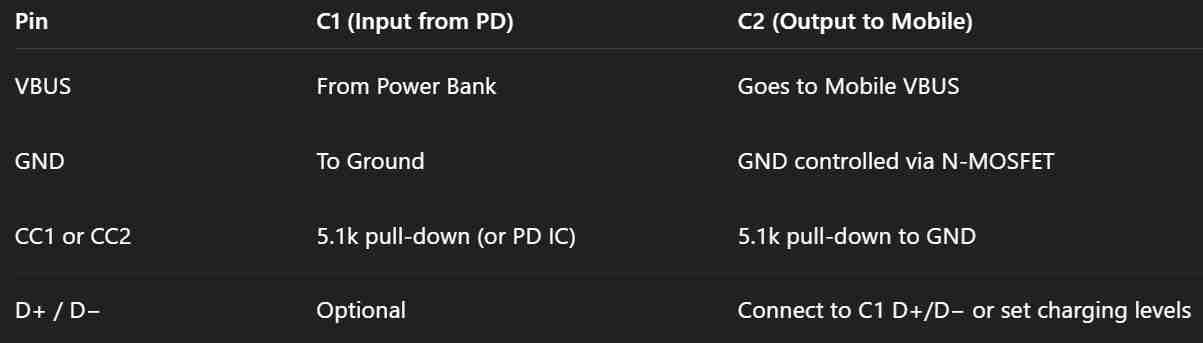
If you are using PD voltages (9V, 12V) then use a buck converter to bring it to 5V/9V for mobile.
Mobile will only draw high current if it detects CC pull-down and correct voltage levels on D+/D−.
Do not switch VBUS or CC with MOSFETs….. switch GND only or use a proper load switch IC.
Remember:
If CC not pulled down then mobile will never fast charge.
If D+/D− float then some phones will still charge fast… others will fallback to slow mode.
Dear sir.
pl down load my sch & inform is it true . I shows 2 pulll down Resistor both side at C1 &C2 side but at the time of placement & solder i do only one. for better coinvent of design i place both on CC1 &CC2 .
https://limewire.com/d/nXbWZ#Ul5FsGLZWU
Dear sir
sorry for repeat. But just inform does my attached file schematic’s is ok ? with this may PD will automatic switch voltage according to load? May i choose 24 PIN or 16PIN c type. Bcz in 24 pin there are some extra pin for data fast transfer. i think no need to choose 24 pin..
But pl conformed last.
https://limewire.com/d/nXbWZ#Ul5FsGLZWU
Nitesh,
I checked your attached schematic PDF and it looks OK overall, and your circuit might work for controlling USB PD 5V output through timer ON/OFF system.
No, in your circuit PD will not change voltage automatically based on load.
Your schematic not using any such PD controller IC like STUSB4500 or similar, so no voltage changing will happen.
if you just want simple 5V output from PD source, and no high speed data or no real PD feature then no need to use 24-pin. Just go with 16-pin USB C connector.
Dear sir
Can u please modify my schematics with Real PD feature with STUSB 4500.
I want to use with input PD 5 to 20 v & high speed charge upto 100W
Dear
i have in my mind that ready made PD came with insight that types of ic u suggested. & while we connect mobile it works as fast charge.
Now I want to make a circuit which has a real PD feature while I connect mobile on output side & input side PD.
So can you give me revised schematics which have a Real PD feature.?
I want to use the Oukitel WP100 Titan mobile. For that i am using PD but finally control fast charging for 1 hours only & then cut for 3 hours.
it’s different when mobile becomes more discharged then fast charge & when mobile charges then charging current is changed or different or low level.
But for this function I am looking for Real PD charging schematics.
i am awning for finial circuit diagram which has real PD with CPin both side either 16P or 24Pin
so pl guide.
Nitesh,
Sorry, it looks difficult for me to create the schematic for your requirement, because I do not 100% information about this concept….
Dear
I think i move in wrong direction. Actually when i connect my power bank who has PD4.0 / QC4.0 include inside & when i charge my mobile then it show fast charge. Now my aim is just control charge time 1 Hours ON & 3 Hours off. so why i choose STUB4500 or any other shrink ic. ? i just regulate PD voltage to 5v for mcu & mcu thrue mos control & MOS thrue GND control of Mobile( load ) & other all line like Vbus , CC1 ,CC2, D+ & D- & If use 16 pin C type connector to both end then not possible? suppose at the timer off at that time my PD entire in stand by mode , so prevent this i connect some dummy load resistance on 5v output .. Now i think u understand well what actually i do.
Nitesh, your method is fully OK. No need STUSB4500 or shrink PD IC because your power bank already give 5V fast charge when mobile connect. So no need to negotiate anything.
You just want to control charging time, like 1 hour ON, 3 hour OFF and for that you use timer with MCU to switch GND using MOSFET. That trick is simple and smart, it will work.
PD going standby during OFF time is normal. So your 100 ohm dummy load on 5V is perfect idea to keep it alive. That fix is good.
Using 16-pin USB-C is fine, just use VBUS, GND, CC1, CC2. D+ D- not needed if no data.
So your setup is clean, cheap and working. No need for extra PD IC.
Dear Nitesh,
It looks good to me, as far as the connections are concerned…
Thanks
Good day Sir
I have a transformer rated 7v 550watts. I want to use it to make a multiple USB port charger for mobile phones.
Each phone needs 5v, 1.5A to 2A. I need your help.
Thanks
Hi Aminu,
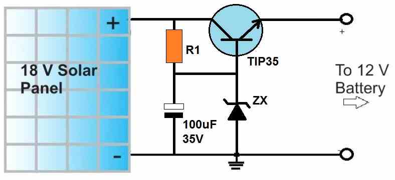
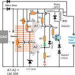
you can try the following design:
Replace the zener with a 5.1V zener, the resistors can be a 1K 1 watt resistor
Replace the solar panel with your 7 V DC supply
Thanks very much.

So, does that mean each mobile phone charger should have a separate circuit like
Or, I can connect as many mobile phones as possible to one circuit.
Thank you sir
Aminu, Preferably each mobile must have a separate circuit as shown above. Instead of TIP35 you can try TIP122
hi
thank you for this I was looking for something like this
I am trying to use quick charge module for charging but I am kinda confused and have couple of questions
1. should the NC and NO of relay be connected?
2. I made this but when i press the push button the relay activates from NC to NO but after 3 to 5 secondes it turns off, I don’t know whats the problem cause I tested the board outside of circuit and it worked fine
Hi, thanks for trying the above circuit.
1) As shown in the diagram, the N/C contact of the relay is unconnected. The N/O contact of the re;lay is used for powering the transformer.
2) The resistor and capacitor connected on pin#9 and pin#10 of the IC 4060 determine the time delay at its pin#3. Did you use these parts as given in the diagram.
To confirm whether the IC 4060 is operating correctly or not you can connect one LED in series with the base of the BC557, and another LED between pin#3 and ground with a 1k resistor
When you press the switch the base LED must illuminate initially and remain illuminated until the time elapses, then this LED should shut off and the other LED must illuminate. The relay should correspondingly switch ON and switch OFF.
Let me know the results once you complete the above procedures.
Hi, thanks for your amazing website and all the effort you put into articles. Would you be kind and explore the QuickCharge or other similar protocols enabling chargers and powerbanks to deliver 9 or 12 volts? I’ve found only one person (embedblog.eu/?p=504) who has made the circuit himself and yet he did it with a special IC and considering I’m in iran and there’s little to no chance I can get my hands on a special IC or order it from china without spending a fortune on it I wanted to ask you to figure out if theres a way to implement the QC 2.0 or 3.0 with an arduino or an attiny85. thanks again and have nice day
Hi, fast charging concept is not so difficult and can be implemented using ordinary ICs. It is just about applying high current at the initial stages until the battery voltage reaches a specific value, and then gradually reduce the current until the battery fully charged.
3 Step Automatic Battery Charger/Controller Circuit
Make this Fast Battery Charger Circuit
I am tasked to oversee an electric motor-propelled feed pellet disperser that is powered by a 6V rechargeable battery (solar panel power source). The device performs well and delivers feed at intervals dictated by an existing timer. This timer is limited however, in that it can only actuate the feed dispenser for 1,2, … , or 6 whole seconds at a time; no fractions of a second allowed. I want to refine the feed intervals by programming to tenths of a second.
I purchased a DROK timer relay. I programmed it to turn OFF for time “CL” (0.5 seconds) after getting a trigger signal, and then turn ON for 2.0 seconds time “OP”. Relay turns OFF after finishing timing.
I checked all this out at home on a breadboard and the circuit (less the timer, of course) worked flawlessly using an LED load.
I couldn’t get the circuit to work in the field! I am connecting the (+)BATT to the timer (default), but now interposing the preconfigured DROK between positive terminal and timer. I figure something is either amiss with my design, or I need to go into the newly fashioned wire connections/splices and replace solder for the wire nuts.
I’d like to use the DROK and not home build a timer relay myself.
>Could you diagram a circuit for me that I can use on this project?
If you can replace the external timers with a single IC 4060 based timer, then probably you can achieve the desired results. A IC 4060 can provide 10 selectable outputs with each output having a delay 50% less than the preceding one, or vice versa. You can either get this in repeatable form or a one-shot latching manner.
https://www.homemade-circuits.com/how-to-understand-ic-4060-pin-outs/
Hi Mr. Swagatam, great circuit !
Please help me to making timer and autocut off phone charger circuit (specialy with super tiny components as single 4060&0.1uf,thats awesome).
Iam using fast charging (5-9V 1-3A) with indicator cable but im NOT SURE ITS SAVE after batterys full at overnight charging (i think thats bad for phone battery).
What should i make to have 2 hour charging but can auto cut off even before time out if batterys full? Also please part list if theres any changes of existing components (for 2 hour timer)
Thank you for your big help
Regards.
Thanks Farrel, All phones have built in state-of-the-art battery protection system with auto cut off so need of adding any external cut off circuit…but if you still want it then I can add it in the above article
Thank you Mr Swagatam.
As we know is yes new phones are have built in auto cut off (I) feature..i just want to add that feature to next circuit that i make from both your design. Please contact me if you made it but i already sub your youtube channel&fb.
Once again thank you a lot..
Hi Farrel, you can try the second circuit from this article, the charger adapter’s mains 2-pin will go the points indicated as “load”:
https://www.homemade-circuits.com/simple-triac-timer-circuit/
Sir Good Morning!! could i ask you a image or schematics on what to do with unconnected pin of any IC?
thank you very much Sir, im sorry to ask because i cant understand when you say it has to be connected to a logic level.
jindro, the inputs of a CMOS IC such as which start with 74XX or, 40XX or 4XXX consist of logic gates in them, for example nand gate, NOT gates etc. When one of these gates are not used or are unconnected, their input pins should be terminated either to the positive line or to the negative supply line…in order to keep them stable.
One more thing, could you edit the design to be UK pluge type which contains 3 pins!
Hope you help me.
Thanks.
the indicated transformer/switch wires will become the inputs for the 220V AC, and a 3rd earthing pin could be included which could be connected with the chassis or the enclosure if a metal enclosure is used, or simply with the body of the transformer.
Hello mr. Swagatam,
Hope you are doing well.
Would you kindly provide me with a software that I could use to design this circuit.
Regards.
Hello Saad,
Do you mean PCB? Sorry I am not practically familiar with any PCB designing software that I can recommend, although you could find plenty if you search online
I mean simulation software.
Thanks for your response.
sorry I do not use simulators, I simulate my circuits in my mind, and according to me the above designis perfect… just needs to be built and tested practically
thanx.i will.
how to calculate capacitor and resistor in transformerless power supply.thnx
you can read this
https://www.homemade-circuits.com/calculating-capacitor-current-in/
hi swag.i have a rechargeable flahlight with capacitor of 584J 400V .it always puff up.it has no resistor across it.what value should i use.
Hi Dennis, It is happening simply because the capacitor is a bad quality capacitor, change it with a good quality one, preferably from some reputed brand. because if it is rated at 400V it can never puff up. the resistor is not compulsory, it may be included to discharge the cap while it is unplugged from mians, to avoid a discharge shock to the user in case he touches the plug pins accidentally.