In this post I have explained a a simple yet versatile foolproof laser security alarm circuit which can be used for securing any concerned premise with extreme accuracy. The idea was requested by GPS.
Circuit Objectives and Requirements
- Your circuits were very useful to me. Thanks for all your posts, but i wanted something different now. I made Transistor Latch Circuit and it worked fine and i am adding dark activated circuit to it.
- I used it for laser security system. So now suppose i used this circuit to cover a room using small mirrors, once the beam is displaced the whole system will be activated but if some one points another laser to the ldr and replace it with the original one the system will not response because ldr will not even know that the beam was replaced.
- So i want a circuit that should be activated if anyone points another laser or light because adding two laser will increase little amount of output from the ldr, so my circuit must be activated if beam is broken or if the amount of light is increased.
- Please help me out to make our area secure from the persons that comes at night without invitation.
The Design
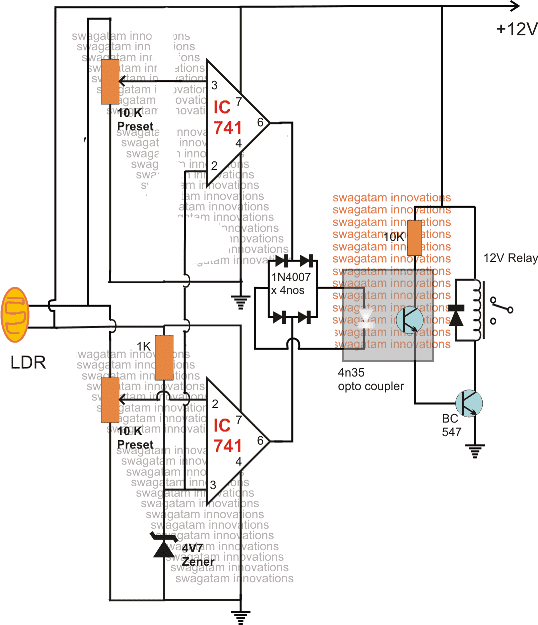
The proposed foolproof laser security circuit can be witnessed in the following diagram:
In the earlier article we saw a rather simple Laser controlled burglar alarm circuit where the alarm is sounded whenever the laser beam incident on the LDR is interrupted.
However as requested above, this could be possibly overridden and disabled by focusing a dummy laser beam at the sensor by a smart intruder.
In order to counter this the design shown above can be effectively utilized which makes sure that only a specific amount of light controls and keeps the alarm deactivated, and varying this spec even minutely triggers the alarm.
Basically the design is implemented through a window comparator stage made by using a couple opamp comparator circuits.
Circuit Operation
As can be seen in the figure, the lower opamp monitors the laser light interruption or any form of decrease in the laser intensity and triggers its output, while the upper opamp monitors the brightness level of the laser and triggers its output in case the laser intensity increases due to any reason.
This keeps the circuit at a sharp edge, wherein any alteration in the laser beam causes the alarm to get activated.
Since both the opamp can have a zero logic only in the perfectly normal laser condition, the attached optocoupler stays inactive under this condition.
However in case the light is disturbed either on the higher or on the lower side, the relevant opamp output goes high, enabling the opto to activate the relay driver stage.
This instantly actuates the relay and the connected alarm across its contacts.
How to Set up the above discussed fool proof laser security alarm circuit.
It is very easy.
Keep the correct laser intensity focused on the LDR and adjust the lower opamp preset such that the lower opamp output just becomes low or zero.
Similarly, also adjust the upper opamp preset such that the upper opamp's output just becomes low or zero.
That's all, the circuit is now set and ready for sensing any form of tampering of the laser beam and to activate the alarm.
Questions & Answers
Hello Sir,
can i put a capacitor just to make the response time a little longer let say a few seconds/minutes?
if i want it adjustable using pot, it is possible?
thanks,
amor
H Amor, yes you can do that. You can shift the 10K from the collector of the opto transistor to its emitter side, or at the base of the lower transistor, and connect a large value capacitor across base emitter of the lower transistor. The collector of the opto now can be directly connected with the positive supply…
Good day, again idol Sir Swagatam,
i’ve just finished the above circuit a minute ago on a bread board and here is what i did and observed:
1) i have no laser yet so what i did is just bring my table lamp near the ldr so that somehow focus its lights on the sensor, then when i put power on the circuit (12vdc) the relay just activated. so i turn both the pots to the point that deactivate the relay or lower to lower the op amps output voltage (1.85vdc in my case). that’s it, its just been set!
2) i have 1pc 10k pot left so just put two 20k pot instead just to make it equal. i’ve bring shadow to the sensor using my hand, then the relay just responded. then i put additional lights on the sensor ( a handy flashlight )
then the relay just reacted to it…. well! its another useful working circuit, and its really a fool proof laser security alarm. Thanks to you idol Sir Swagatam….God blesses you more.
amor
That’s great Amor, glad you could make it so easily and successfully.
And thanks for the detailed explanation, it will inspire others also to build this simple yet useful circuit.
keep up the good work
Can i use a AC 220V light instead of this led? I want to use a ac light to use as a alarm in my security system.
you can, but the light should be in the form of a focused beam
Thank your for your reply.
Good day to you sir swagatam, I am roldan from Philippines 35 years of age. I am so fond reading your articles about security system. I am not an electronic engineer, but I can manage to trouble shoot minor electronic problems. I also have a basic knowledge on electronic schematics… I have already scans all your schematics about cell phone projects, but still I did not found the right project I wanted to built… a favor from you, is all im asking for.. if gods will…
My request :
1.) A security alarm (i.e. burglar alarm) using laser, once that an intruder lurks in the perimeter it will eventually trigger/dial my cellphone, same as the idea of your CELL PHONE DOOR LOCK CIRCUIT. Instead of pushing the car central lock instrument, it will dial my number thru a GSM cell phone. so that I am aware that somebody is/were inside my house. I am always away from my house.
2.) I am thinking about using 2 cell phone, 1 unit is for the alarm system that will dial me in case of an intruder is inside.
Hoping for your kind consideration about my request sir, till next.
Sincerely,
Roldan
Hi Roldan, I'll try to design it soon, however it won't be a Hi-tech equipment but nevertheless will do the job faithfully.
It won't be a Hi-tech since we are modifying a cell phone as the GSM transmitter and not using a professional GSM module,
Hi Swagatham
Is it harmful to eyes, the laser light available with keychains….? Which cIass is such laser beams….? I am afraid, so I have never attempt to make circuits using laser light. Thanks in advance for your reply.
Hi Anil, yes definitely it is harmful if it is focused into the eyes in any manner.
But there's nothing to be afraid about these gadgets because as long as we are not looking into the beam, it is quite safe….even high watt LEDs are as dangerous as this if looked directly into them.