The current controlled circuit of a laser pointer power supply explained in the following post was requested by Mr. Steven Chiverton (stevenchiverton@hotmail.com), who himself is an intense electronic hobbyist and researcher.
Technical Specifications
Dear swagatam,
I'm emailing you to ask you for your expertise, and you being one of India's finest electronics engineers I thought you be the best man in the world to know, bear with me my friend its a bit of a long story.
I brought some 10 milliwats laser diodes from xxxx electronics here, the data on them isn't much but maybe enough to go by, they are 2.4 volts and the threshold current is 24 milliamps and the maximum current is 40 milliamps
Now I've looked all over the net for a power supply circuit using the lm317 regulator for this diode but there's circuits for other diodes only but there voltage and currents are different
So trying to find a simple lm317 regulator circuit that will deliver 2.4 volts dc at up to or near 40 milliamps is hard . so I used an lm317 regulator calculator for voltage and
I breadboarded it only to find out the voltage output was no where near the output of 2.4 volts I wanted , despite what the lm317 regulator calculator says
I wanted 40 milliamps or to be safe just under it so I used the lm317 current regulator calculator and the resistor I entered got me 40 milliamps
But when I bread boarded it I got no where near it . so the best way to go is may be to modify an already existing laser power supply for a laser diode
I know nothing about to try get the 2.4 volts at near 40 milliamps so ill include one here can you modify the circuit to deliver 2.4 volts dc at near 40 milliamps for me and powered from a nine volts battery .
Thank you swagatam I hope you can get it right where I've failed .
The Design
The required laser pointer driver circuit was actually very easy to design, thanks to the versatile 317 IC, you can do almost anything with this chip.
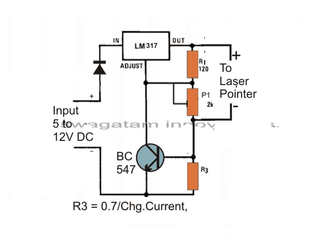
As shown in the figure, a single LM317 is used for acquiring the required precise 2.4V output at 24mA current.
It's a standard 317 variable power supply design. The preset P1 is used for setting up the 2.4V output.
Or alternatively P1 may be replaced with a fixed resistor of 110 Ohms, which would yield exactly 2.4 volts at the output
R3 is adjusted for getting the 24mA threshold current limit.
As per the formula, the current control resistor R3 may be calculated in the following manner:
R3 = 0.7/0.024 = 29 ohms.
Feedback
Thank you very much swagatam ill give that circuit a go to just have to round up the resistors I need out of a draw full of them and the 110 ohms isn't an easy one
But resistors are never the exact values these days that's why they have the gold tolerance bands they are either above or below there values ,
And also due to the various calibrations of digital meters they don't all read the same values so anyhow 110 ohms is close to 120 ohms is a try and electronic calculators and theory circuits don't calculate values using the gold tolerance bands
So the actual results are not known till the actual circuit build is done or the resistors are measured to the present calibration of the meter you use to test them with ,
Thanks swagatam pal ill get back to you soon hopefully the red 10milliwats laser diodes hold up ok and at just over 6 dollars each I have 2 only so ill try them soon.
More Feedbacks from Mr. Steven
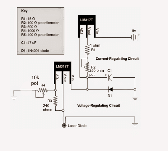
Here's a copy of the modified laser driver circuit you once emailed my back can you modify it again to be adjustable up to 1.2 amps max and minimum of as low as you can get it , as I want to build another but with a higher adjustable current.
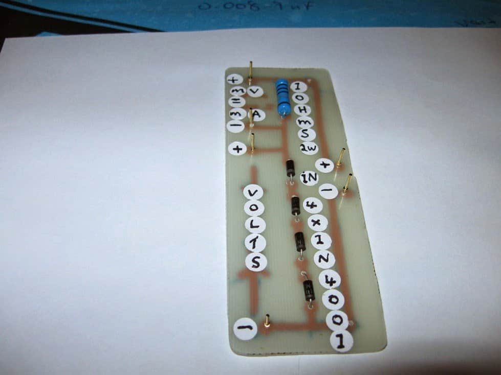
DDL Laser Circuit
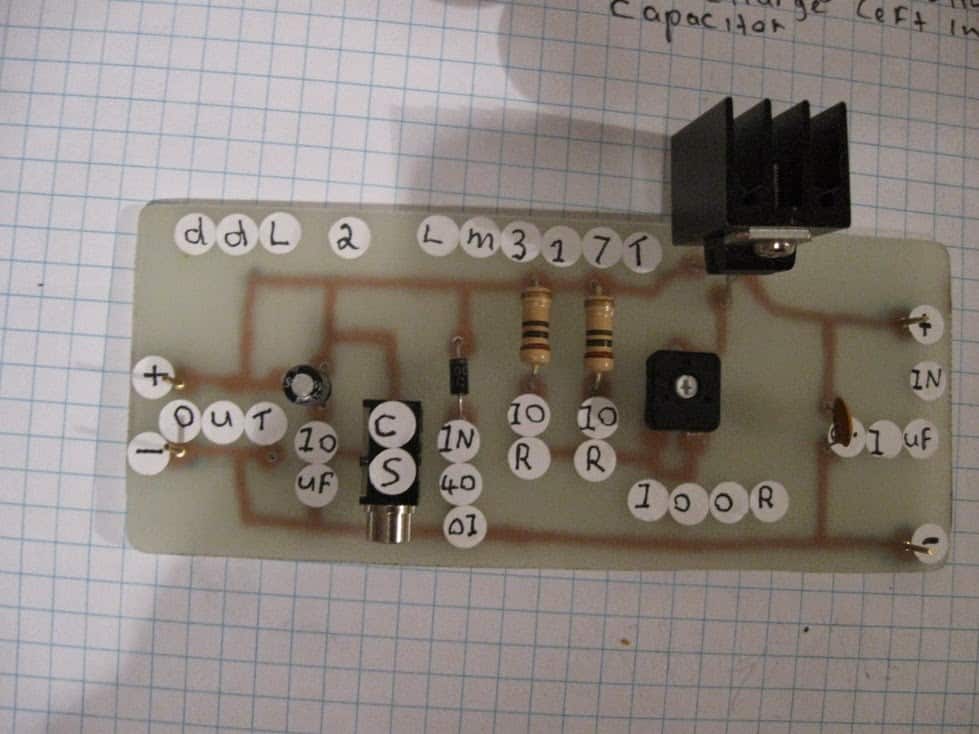
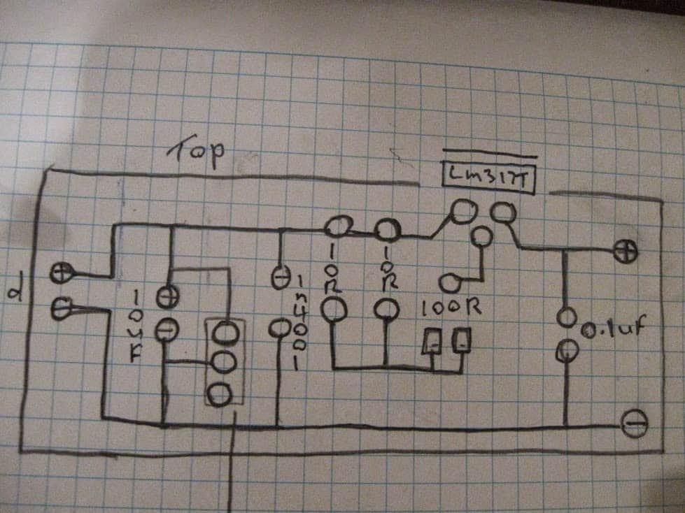
Here's a new printed circuit version I made from a schematic from the laser pointer site this is for the ddl laser driver circuit , its a test load circuit for that so you can adjust the ddl laser diode driver and use the next circuit the test load circuit for that to tune this ddl laser diode driver I think its for 2.8 volts laser diode or near that
Improving the Laser Circuit Further
Here's the latest swagatam,
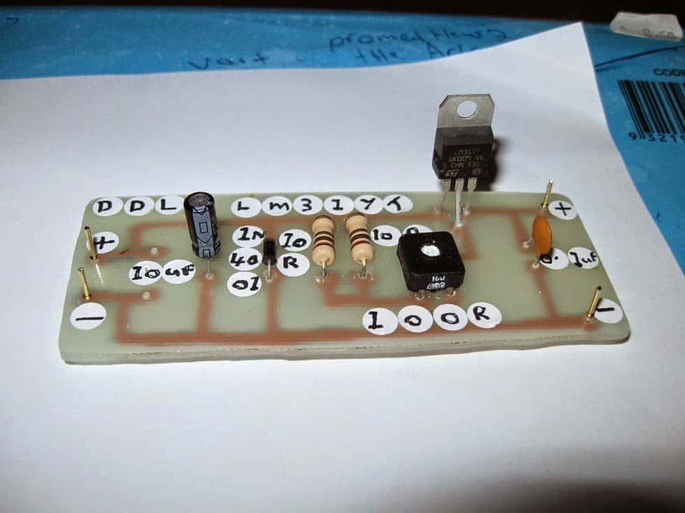
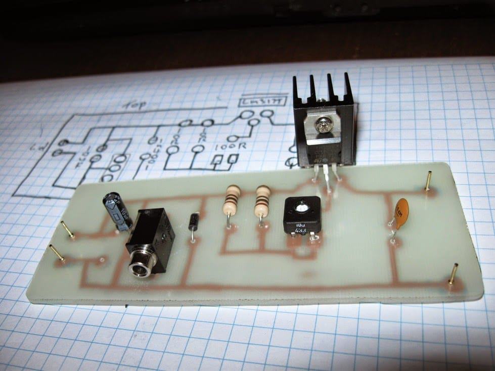
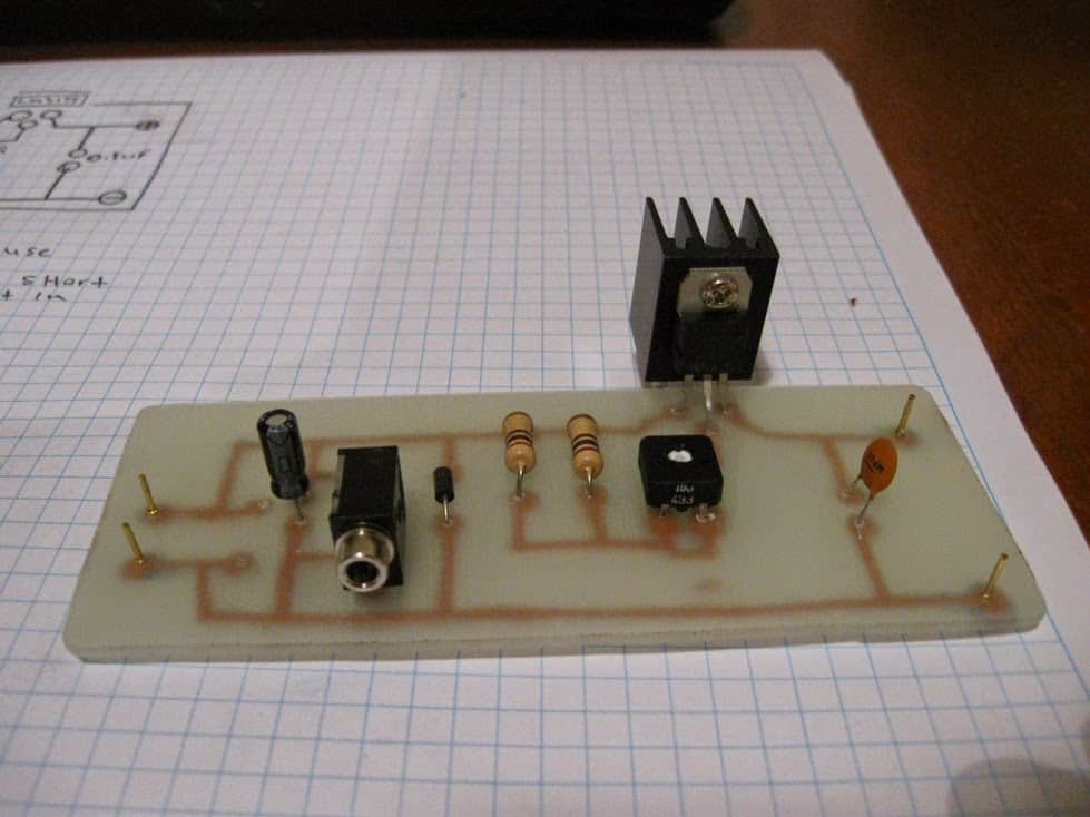
I've made a printed circuit of another ddl laser diode driver from the laser pointer forum
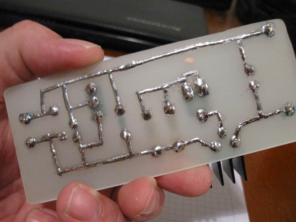
So I've added a new feature to it to solve the laser diode damage problem caused by an undischarged electrolytic capacitor in the circuit near the output to the laser diode
Even though I got the same thing when I blew my test laser diode when I forgot all about the 10 uf 16 volts electrolytic that caused it .
Here is my solution , look at the picture and next to the electrolytic capacitor is a plain dc input socket and I've used just 2 out of its 3 pins so it bridges the capacitor and forms a short to discharge it
To unshort it just put any plug into it and it opens the short so the capacitor can charge during use of the driver and when you finish pull the plug out to shorten the capacitor again fail to do so would result in the charge left in the capacitor being dumped into the laser diode and thus over volting it and blowing it


Questions & Answers
Thank you sir
I need to drive laser diode for 30 watt. can you explain the principle to increase the power output to diode laser drive circuit because need to PCB making
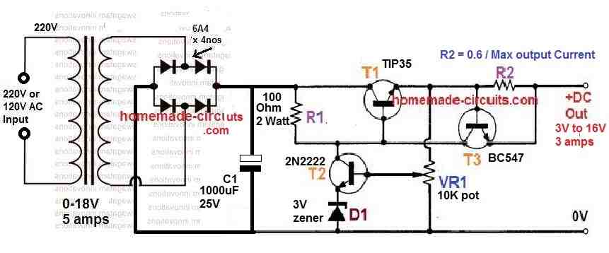
No problem Ahmed, you can try the following design and customize it correctly to suit your specific laser diodes needs:
Let me know if you have any further doubts…
Thank you sir
Hello.
Thank you for your useful content.
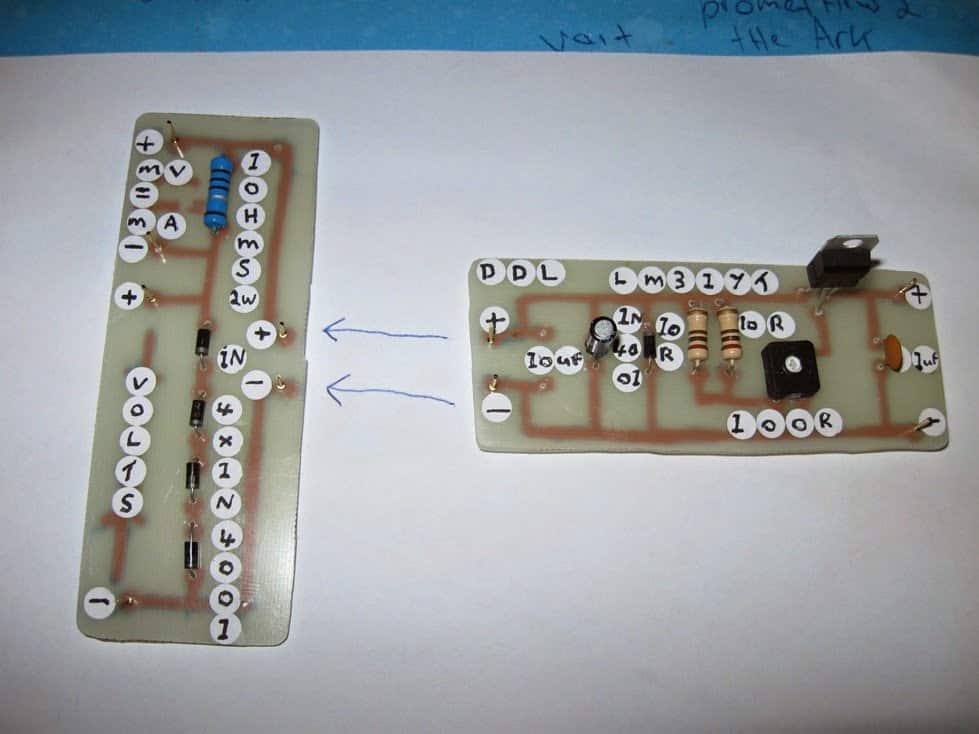
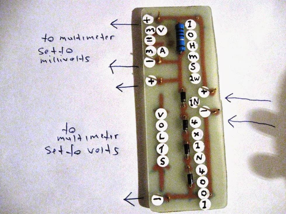
I wanted to know the second pcb circuit that has 4 normal diodes and… on one side of which you wrote the voltage and current adjustment output with a multimeter, how exactly should it be used? I mean, should it be mounted and installed on another main board?
Or just before using the main board, it is connected only to adjust the output of the main board?
Didn’t you use the schematic diagram image that is above these images and in its specification 2 to LM317 are used to adjust both voltage and current for this driver? Because I first thought that these two pcb boards are the same diagram; But then I realized that you only used one lm317 and in that diagram there is no mention of 4 ordinary diodes and only 1.
Now, which design is better and more suitable for me to use for the construction and implementation of the burning laser pointer???!!
Hi, please ignore the PCB diagrams and the two LM317 circuits because those are unnecessarily complicated.
According to me the first circuit is the best since it is simple and has a constant voltage and constant current output, both adjustable.
I would recommend using a fixed resistor instead of the preset P1.
For finding the exact value of this fixed resistor you can use the following software:
https://www.homemade-circuits.com/lm317-lm338-lm396-calculator-software/
Hi Swagatam, I was wondering if i could have a call/discussion on a hobby project that is bothering me for several years. i find your work might be suitable ,or you might be able to guide me in the right direction.
Pls get back to me if you are interested . I also welcome anyone who have background on building/ laser guided gyro tracking devices.
Thanks Manohar, I appreciate your interest, however I do not have the necessary expertise in the filed of laser guided gyro tracking devices so I may not be able to provide any useful suggestions. I hope somebody else from the community with relevant expertise is able to discuss this further with you.
Respected Swagatam sir ,I want to get the results of photodiode and want to analyze the feedback of the photodiode through oscilloscope, sir will you please help me how to get the feedback circuit for photodiode.
Thanks
Hello Safi, Photodiode will convert light to DC, which can be easily measured using any small oscilloscope.
Respected sir,may I use trans ampedence amplifier for output current.
thank you
Hi Safi, the output from the 317 regulator is a current controlled voltage, so no need of any converter.
the photodiode is also present in the laser diode
Hi, I have laser diode 450nm 5WATTS , i bought it from banggood. But its power supply module is stopped working . I checked this from electrician he told me that power supply is faulty and laser diode is ok. BUT HE COULD NOT FOUND WHERE THE FAULT IS, CAN YOU HELP ME OUT FOR MAKING A POWER SUPPLY FOR THIS DIODE , I DONT KNOW HOW MANY AMPERES AND VOLTS THIS DIODE NEEDS TO OPERATE, AND THATS WHY DIDNT’ TRIED TO RUN IT ON ORDINARY POWER SOURCE.
Hi, you can try the circuit explained in the following article:
Laser Diode Driver Circuit
Normally, laser pointers are operated with 3V or 3.7V V DC supply.
You can adjust the output of the circuit to precisely 3.7V.
Since it is 5 watt, so the current for the laser will be 5 / 3.7 = 1.35 amps
As per this current, you will have to use a R3 resistor with a value = 0.7 / 1.35 = 0.5 ohms , 1 watt
Hi @Swagatam,
I wonder how the circuit will look like if only I have a 3.0V voltage input. I believe I can’t use the LM317 in this case. Do you have any suggestion to for a 5mW laser driver from a 3.0V input?
Hi MA, you can try the transistorized version of the current limiter explained in the following article, and use it for your laser diode:
https://www.homemade-circuits.com/universal-high-watt-led-current-limiter/
Thank you Swagatam, didn’t know current limit circuits also work and I wonder how they compare to constant current.
From what I read after some research:
Current limiter: does never supply more current than the limit, but can provide less.
Constant current source: the current sourced/sinked stays always the same.
Which of them do you think works better with lasers? Or both can do the job?
Thanks MA,
According to me both the concepts are one and the same. Both the systems will not allow the current to increase beyond a set threshold, however if the input current tends to drop then both the systems will drop the output current below the intended threshold….so no difference according to me. Both the types will not generate their own current to stabilize the output.
Yes a current limiter can be used to safeguard a laser device.
Thanks alot. i will try it.
These are awesome. Love the fact you can turn on laser beam without having to hold the button the entire time and the fact that they are rechargeable. Plus my kitties love it and the little cute mice that came with it.
Thank you!
Good day Sir Swagatam,
i have a laser pen 20mw 3v my son accidentally connect to a battery with the wrong polarity and
its no longer working i think the circuit was already fried. my question is can i still use the laser head and make a new driver for it?
Thanks,
amor
Hi Amor, you may have to isolate the laser and test it separately with a battery, if you find it OK then you can use it it with another driver circuit.
Hello Sir,
can i use the above circuit my laser head has 3 pin 20mw 532nm 3v
what will be the value of R3 please! i cant get it using the formula.
Hi Amor, the second design would be more appropriate, make sure to fix the current at 6mA and voltage to 3V, for your laser, and the input supply should be around 6V minimum.
HI,I want a block diagram and circuit diagram of laser diode driver circuit by using LM317 IC.
Hello Swagatam, thanks for your help in another post! I am trying to understand how these circuits work, and I am lost. Can you please guide me to the right direction?
In this above example you write that if P1 is 17.5ohms, Vout will be 2.4V. Now I dont see why this is the case.
My understanding is that R1=120ohm determines the current to be 1.25V/120ohm=10.41mA. P1 should be selected so that Vadj is Vout-1.25, right? Vout should be 2.4V, so Vadj should be 2.4-1.25 = 1.15V. I know the current flowing through R1 flows through P1, too, and now I know what voltage drop I want. Now the resistance will be Vadj/I = 1.15/0.01041 = 110ohm. R3 is 29ohms, I guess we should subtract this, so for P1 I get 110-29 = 81ohms. This is waaaay off. What do you think went wrong?
Thank you for your time and efforts!!
appreciate your response…but it's your investigation that helped me to correct the fault 😛
regarding the 29 ohm issue I was thinking of pulling of the P1 end and connecting it with the emitter side negative of the circuit that would solve the 29 ohm from getting on the way of the calculation.
Well, that teaches me a lesson: don't investigate, use! 😀 I guess however much I would like to be, I am not a practical person. I get always lost in the details.. :/ LM317 calculator! Great tip, thank you!! Keep up the good work!
…and yes 29 ohms also needs to be included therefore, the net values ought to be 81 ohms, that makes sense.
however since the load ground is connected between the two resistors so that makes things little confusing
….Hello Balogh, yes 110 ohms is correct, I think I made a mistake while calculating this resistor.
Hello Balogh,
I have never investigated LM317 ICs so deeply, simply because I could get the required results quite easily from these circuits without any hassles… so I won't be able to verify your calculations immediately.
I got the 17.5 ohm value by using an online "LM317 calculator" software, and these calculator will always give you the most relevant and correct results, you can try it out yourself.
Or may be you can refer to the datasheet of the IC itself for studying the various formulas presented in it and compare your results with it…I am sure that will help you to understand the concept with greater details.
Excuse me sir, unfortunately the 2K pot is not available in the electronic shops so I decided to buy the nearest but larger than 2K which is a 10K trimmer. Hope this works.
It will work fine, but getting the exact voltage setting will now be slightly more time consuming than a 2k pot.
excuse me sir Swagatam, I made a 5vdc source for my burglar alarm which uses a laser pointer. I bought a cheap laser pointer that has a built in circuit with a switch, little SMD resistor and three little 1.5v batteries. I just would like to ask if your updated circuit can be used for this kind of laser and 5v source. thanks a lot.
laser specs:
5mW
25mA
3-4.5vdc
you are welcome moiiloves
thank you very much sir. I will try this right away and update you as soon as I finish applying the circuit
Hi Moiiloves, yes you can use the first circuit for your laser pointer, but before connecting be sure to adjust the output voltage using the 2K preset precisely to 4V and R3 for your case should be
0.7/0.025 = 28 ohms 1/4 watt
my comment didn't post so here we go again , use a laser diode driver circiut test load to tune the output of your driver to the correct milliamps to power your laser diode look in the laser pointer forums for the details
Hi, Mr Swagatam, I'm a new electronic hobbyist and I have a 650nm 6mm 5V 5mW Laser Diode, with an operating current at <40mA. Can I use this circuit as a driver circuit or do I need to modify it ? Please help. Thanks
Hi Sattesh, you can use this circuit, just make sure that you adjust the pot to obtain an exact 5V at the output…… and use 15 ohm for R3