The IC 555 is a popular timer IC which we can use for making different types of inverter circuits. With a few extra components we can make the IC 555 generate switching pulses, and then we can use these pulses for converting battery DC into AC power.
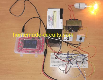
In this article we will look at 5 different inverter designs using the IC 555. These include simple square wave inverters, full bridge inverters, SPWM sine wave inverters and one design with automatic battery protection.
Each design works in a different way and has its own good points and limitations. So you can select the design according to your requirement and then visit the respective detailed article to understand the complete circuit diagram, component values and working principle.
Important: These circuits can generate dangerous high voltage AC. Some designs also use high voltage DC internally. So let us be careful and never touch the circuit while it is powered. We must also check the circuit properly before building it, since not every circuit has been practically tested.
1. Basic IC 555 Inverter Circuit
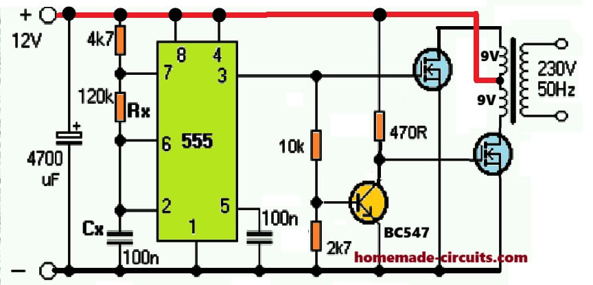
This is one of the simplest types of inverter circuits using an IC 555 timer. Here we configure the IC as an astable oscillator so that it can generate low frequency switching pulses.
We can use these pulses to operate a power transistor or MOSFET stage connected to a suitable transformer. The transformer then converts the battery voltage into a higher AC voltage.
This type of transistor inverter can be quite simple to build, so you can use it for understanding the basic working principle of an inverter.
The output is generally a square wave, but it is not the same as the pure sine wave that we get from a normal household AC supply.
We must select the oscillator frequency, transistor ratings, transformer rating and battery capacity correctly, so that the circuit can work properly.
Read the complete circuit here: [BASIC IC 555 INVERTER ARTICLE URL]
2. IC 555 Full Bridge Inverter Circuit
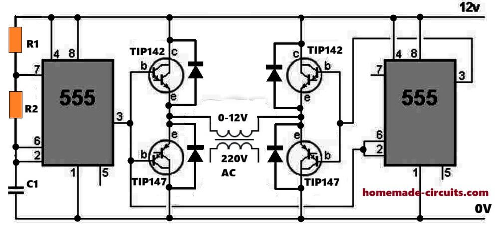
A full bridge inverter uses four switching devices arranged in an H-bridge configuration. Here the switching devices work in pairs so that they can reverse the polarity applied to the load or transformer.
We can use the IC 555 as an oscillator for generating the required low frequency switching signal. But we also need additional circuitry to produce the correct switching sequence and prevent the two devices in the same bridge leg from conducting at the same time.
A full bridge arrangement can make better use of a suitable DC supply and transformer, but the actual performance depends on the circuit design and the switching devices we use.
The original circuit shown in this design uses an unusual supply arrangement, so we must check it carefully before construction. We should not assume that it is a tested 200 watt inverter.
Read the complete circuit here: [IC 555 FULL BRIDGE INVERTER ARTICLE URL]
3. IC 555 Modified Square Wave Inverter Circuit
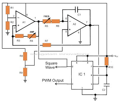
A basic IC 555 inverter produces square wave AC. But if we want to get a waveform closer to a sine wave, then we can use a pulse width modulation technique.
In this design an operational amplifier circuit generates the reference waveforms required for producing SPWM pulses. The IC 555 is then used to generate pulses whose widths change according to the modulation signal.
These pulses control the power switching stage and transformer. With a properly designed output stage and suitable filtering, we can get an AC waveform that is closer to a sine wave.
The quality of the output depends on the PWM generation method, switching stage, transformer, output filter and load.
This circuit is more complicated than the basic square wave inverter, so we must check the oscillator frequency and switching arrangement carefully before building it.
Read the complete circuit here: [IC 555 Modified Squarewave INVERTER ARTICLE URL]
4. IC 555 Sine Wave Inverter Using SPWM
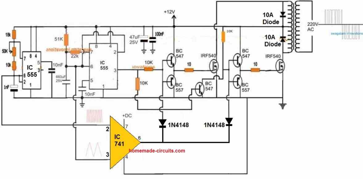
This is an easy way of making an SPWM inverter using the IC 555 together with an operational amplifier such as the IC 741.
In this design a high frequency triangular waveform is compared with a lower frequency reference waveform to produce pulses with changing widths. These SPWM pulses are then used to control the inverter power stage.
The IC 555 oscillator provides the timing signal, while the additional circuit generates the modulation required for shaping the output waveform.
The good thing about this method is that we can build the timing and modulation sections using commonly available components.
But we must make sure that the switching frequency, output frequency and gate or base drive signals remain properly synchronized. A suitable output filter may also be required, depending on the design.
Read the complete circuit here: [IC 555 SPWM INVERTER ARTICLE URL]
5. IC 555 Transformerless Inverter Circuit
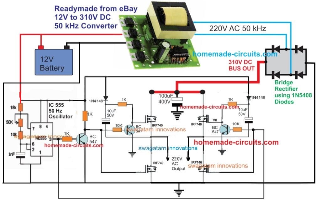
This design uses an IC 555 oscillator to control a full bridge made from four N-channel MOSFETs.
Unlike a normal low voltage transformer inverter, this arrangement uses a DC-to-DC converter module to get a high voltage DC supply. The MOSFET bridge then switches this DC supply to produce an AC output.
So in this design the high voltage conversion takes place electronically instead of using a conventional low frequency transformer.
This arrangement can reduce the size of the magnetic components, but it also needs some extra care during design. The DC-to-DC converter, MOSFET bridge, gate drivers and protection circuits must all be suitable for the operating voltage and load.
Safety warning: The high voltage DC bus can be lethal even when the input comes from a low voltage battery. So we should not treat this as a beginner circuit.
Read the complete circuit here: [TRANSFORMERLESS IC 555 INVERTER ARTICLE URL]
Which IC 555 Inverter Circuit Should You Choose?
The best design depends on what you want to build.
A basic square wave inverter is the simplest starting point, so you can use it to understand how an inverter works. A full bridge design may be suitable when its switching and driver stages are designed properly. An SPWM inverter needs some extra circuitry, but it can produce a waveform closer to a sine wave.
A transformerless inverter is more complicated since it uses a high voltage DC bus. A design with Arduino battery monitoring adds control and protection functions, but it also needs suitable programming and testing.
Before selecting a circuit, let us check the required output voltage, output frequency, continuous power rating, battery voltage, transformer rating and expected load.
We should not select an inverter only by looking at the power rating mentioned in the circuit description. The actual output power depends on the complete design and the ratings of the components we use.
Final Words
The IC 555 is a useful timer IC which we can use for making many types of inverter circuits. By changing the oscillator, modulation circuit and power stage, we can build different inverter designs for different purposes.
The 5 designs explained above gives us a starting point for understanding these possibilities. You can visit the individual circuit articles to see the detailed schematics and explanations before selecting a design for construction.

Questions & Answers
Please sir what is the Watt of this inverter ?
Will depend on the trafo wattage and the battery AH capacity.
Please can u help me and tell me how may i know the transformer WATT because i have UPS transformer but i don't know it WATT?
apply mains AC across its mains side and then using an AC ammeter measure the current directly across the other side wire ends…then multiply the reading with the voltage specification of those wires
hi swagatam for the first diagram what is the rating of the transformer
Hi Davis, it can be as per your own desired specification….
i am greatfull so much and i am very appritiate for your site
pls sir, can you help me with the diagram of IC 4047 and fets 1kw diagram since thats the only ic i can get around. Thanks
Eric, you can try the following design
https://www.homemade-circuits.com/2014/11/48-v-inverter-circuit.html
you can replace the BJTs with FETs, and use 100 ohm resistor with their gates
sir what are the appliances does the circuit above will power ?
It will power most of the equipment which use internal SMPS
sir can the circuit above power a fan without a noise???
you can connect a capacitor with the fan to reduce noise
I av 12v 0 12v to 230v AC, will it work on the cirvuit above? sir
yes ti will work
sir can i connect the above circuit with 6-0-6 ? and how the watt be ?
it can be used if the battery is also 6V
I am using a simple transformer. When I press ctrl+E, but tell me that how can i calculate these values like primary inductance, secondary inductance etc. Can you suggest me some calculator for this purpose?. My requirements are below: primary voltage: 220V, 50Hz secondary voltage: 12V, 1A
I have already discussed how to design an inverter transformer in this website, you can refer to that article. you can find it through the search box above or by Google search..
Is the citcuit square wave or sine wave? If square wave where to attach chopper to it and make it modified sine wave? Thanks
it's square wave, add chopper to the bases of the NPN/PNP
sir what is dis chopper all about. is it a circuit. if yes can u upload it, let me take a look at it. thanks
you can learn the details here
https://www.homemade-circuits.com/2013/04/how-to-modify-square-wave-inverter-into.html
Domnule Swagatam Majumdar,va rog sa-mi spuneti daca acest invertor poate fi folosit la o pompa electronica pentru centrala termica,atunci cand reteaua de curent a cazut.pompa consuma 40w.daca nu ce modificari trebuie aduse.Scuze ca nu vorbesc engleza.pls raspundeti.tank you
da, acesta poate fi folosit pentru orice aplicație preferată ca pe alegerea ta
hello sir swagattam, I designed an inverter, it is working perfectly. but my problem is '' the heatsink ther was not fan connected to it and it is hot so much. I need an automatic fan circuit for cooling of the heatsink whenever it start heating the fan will automatically blowing, and whenever it stop heating the fan will automatically stop…. thanks
hello chucks, you can try the following concept
https://www.homemade-circuits.com/2015/03/fan-speed-controller-for-heatsink.html
Please Sir help me as you are doing to us. please guide me how i am going to calculate battery mAH . Assume that the battery is 12v 100mAH and connected with 500watt inverter if i connect 7 phone chager each is 6 watt and 9 watt CFL how many are hours may the battery's charging take before the it finish
I guess you meant to say 100AH battery??
you simply have to divide the battery AH with the load current, and multiply the result with 0.6, that will give you the approx battery back up time.
If i get u for example if my current is 9 watt and my battery is 100AH THE ANSWER IS 100/9=11.1*0.6=6.6 hours ??
It should be load current, not load wattage….your procedure was correct but in place of 9 watt you must apply current.
current can be found by dividing 9 watt with load voltage.
thank sir may GOD expand ur idea more again
is current the same with amp?
amps = 1W / 230V
= 0.004348A ??
yes that's correct. current is measured in amps.
thank u sir
My another Qestion Sir, for instant if i want to modify an low watt inverter less said 50watt please what and what do i going to change or to add. may i going to change height voltage transformer or i am going to add more transistor in pararal please which one should i going to do??
what modifications do you want to make??
hello sir,
I'm very grateful you have deigned to answer my questions by posting an inverter circuit NE555 ic that works on ferrite transformer, I really hope you do not get bored if I will be asking a lot more about this circuit.
I pray that God bless your family
You are welcome Ningrat!!you can feel free to post new comments
Thank you sir,
I am having trouble finding diodes past 10 amperes, .. is there a best solution for it
you can try 6A4 diodes, see if they work alright?
sir, this circuit produces high frequency ac voltage 50kHz whether it can converted into low frequency ac voltage between 50Hz – 60Hz
Ningrat, the Rt, Ct values in the second circuit determines the 50Hz frequency for the load.
you can get the formula in the datasheet of the IC
if we change the value of Rt and Ct to get 50Hz whether it could be applied in the ferrite transformer?
I mean a string of additional output transformer that will turn into a 50Hz 50kHz frequency
ferrite transformer is supposed to be connected with the first diagram which has 50 Khz frequency, the lower circuit needs to be set at 50 Hz….
the load or appliance can be directly connected the lower circuit mosfet.
the 50 khz from the top circuit is fed to the second circuit through the bridge rectifier
if the output of the circuit is converted into a dc voltage using a diode bridge and then a dc voltage is converted back into an ac voltage what it could be?
series such as what can turn into a dc voltage low frequency ac voltage in this issue?
ferrite core can be operated only with high frequency, that's why initially high frequency is used for stepping up the battery voltage to 220V and then it is converted back to low frequency for our home appliances.
Sir,
series such as what is used for converting high frequency to low frequency
the four mosfets are toggled at the low frequency 50 Hz for executing the 50 Hz AC on the load
I'm very sorry sir, too many of my questions got me so confused
actually i need a simple circuit using a transformer ferritte inverter that can be used to supply domestic appliances such as water pump, fan, TV and other types of induction motors.
The circuit may be able to use ic TL494, NE555 because the component is very easy to be in my area, there are some circuit which uses components that are very difficult in the can in my area wide ic3524,3525, IR2153, and other types
Ningrat, you can try the above explained IC 555 based ferrite circuit, it will certainly serve the purpose as desired by you….
or you can try the following design also
https://www.homemade-circuits.com/2013/10/modified-sine-wave-inverter-circuit.html
a pressing issue, why I wanted to make this inverter because in the area I frequent power cuts in 4 hours
and if it's quite possible it will greatly help me
Hello, sir
Can you help me again, I have to stand by charger circuit using ferrite transformer would I plug the inverter circuit that I have made.
I had been using stand by charger which uses iron transformer I think if the circuit uses ferrite transformer would facilitate.
Thank you so much my regards
Ningrat, Please give the technical specifications of your charger
I need a circuit standby automatic charger for charging 12volt battery with a maximum current of 2 amperes, this circuit will be installed in the inverter.
Automatic question is:
1. The automatic cut off the charging current when the battery is in full condition
2. The inverter will turn on automatically when power outage
3. The inverter will automatically turn off when the power flame back.
Thank you so much my regards
Ningrat, you can try the second circuit from the following article
https://www.homemade-circuits.com/2011/12/how-to-make-simple-low-battery-voltage.html
the charging input can be acquired from any suitable power supply source…
Thank you very much sir,
sir if I could replace the transistor BC547 and bc557 with other types may BD139 and BD140 or s8550 and s8050? if it can do I need to change the value of the other components?
my regards
Yes you can but it will be unnecessarily costlier….
no other components will need to be changed.
I tried to replace the transistor with s8550 -s8050 and a series of work thank you very much sir
my regards
that's great Ningrat, congrats to you
Sir,
maybe you have recommendations dc converter circuit 12volt to 300volt DC and converted into 220volt AC
you can try the circuit explained in this article, you can replace the IC with the above 555 circuit stage
https://www.homemade-circuits.com/2013/09/half-bridge-mosfet-driver-ic-irs21531d.html
Hello, sir
I hope you are always healthy, ..
sir if i can send an email to you because I want to discuss a scheme and I find it difficult to attach the scheme in this forum
Hello Ningrat, for a long term consultation you can signup and start posting here
/forums/forum/electronic-circuit-discussions
or for brief discussion you an use my email admin @ http://www.homemade-circuits.com
hello sir, pls I need ur assistance
i'm designing a digital display circuit, ther was a component I can't find in ma country such as 2N3053 transitor. is ther any other transistor use to replace and also gv me the same configuration it does???? thanks
I have already replied to the same comment in the other post
you can use a 2N2222 instead
Sir
if the email you have received from my
Ningrat, I did not get any email,
please send it again or post it in the following forum
/forums/forum/electronic-circuit-discussions
in this forum I am the admin.
hello sir, I do not see ur reply in post, please reply me here so that I will carry on my project thanks
Chucks, you can use 2N2222 in place of 2N3053
hello sir,
Best wishes
sir, can you help me make an inverter circuit with an ac voltage pulsed out of 500watt, so if out burdened by 500watt light the lamp may blink and blink rhythm can be set using a potentiometer with a frequency of at least 50Hz maximum out 100hz.
thank my regards
hello ningrat, sorry I could not properly understand your requirement and the application need of the circuit
Sorry sir if it is so contrary to you due to certain factors, actually I wanted to create a series of electrofishing to output a pulsed ac voltage, …
once again please forgive me if my request is contrary to your
my regards
Ningrat, you mean to say you want a 220V generator circuit having a variable frequency adjustment??
Hello sir, can you pls help me with 12v dc to 60v dc 100w circuit diagram please. Thanks
Hello ERic, you can try the second circuit concept from the following article
https://www.homemade-circuits.com/2014/05/generating-electricity-from-road-speed.html
sir, i have made this on proteus but haven't got the desired output yet could u check it plz ?? i have to make an 100 watt inverter for my university project .need ur help sir
asad, sorry I cannot verify a software interpretation, but I can guarantee that this inverter will perform as specified when built practically without errors..
thanks for ur reply sir, hope u r doing well.i have some questions .which circuit should i use ? what is the transformer & battery ratings ? is that a sine wave or square wave inverter??
if you integrate the second circuit, then it will become a sinewave.
transformer and battery rating can be as per your inverter power requirement…
please sir help me as urgent,
I have build the first circuit but before testing i will like to insure the curret polarity of the zener diode, as you said the mosfit will conduct base on the negative and positive pulse of the 555 timer, so by looking at the circuit you can see that the zener diode is facing positive all of them to the mosfit, that is at a positive pulse one of the mosfit will not conduct. or the are as it is. Help
Kabir, the zener diodes in the first circuit are correctly placed.
the positives from the emitters of the BC547s will enter through the zener cathodes and reach the mosfet gates.
zener diodes do not work like rectifier diodes.
Sir, I have noticed my problem, that IRF547 In the circuit, I have replaced it with IRFP450, which prevent the circuit to work; later I just refer back to your 555 timer DC to DC boost converter, I just eliminated that 10k and 9v z from the circuit and the circuit is now working perfectly. But I tested it with 12v battery and achieved 320v DC out put. Sir my question is when I use 60v input from the solar panel, the output voltage will change or not? My ferrite core primary winding is 50 tune with 5 strand 20swg and the secondary 200 tune with single 20swg. You can see that I have altered your specification OF SWG in the circuit; this is because I determined the output load of my inverter and maximum current for the wire gauge, that 0.5mm seem like can not carry high load of current, and that 1.00mm can not carry high input current. But if I when wrong base on my assumption please correct me.
Hi Kabir, the 9V zener could be reduced to some lower value, say 4.7V etc because the zeners help to achieve a dead time which is important for the inveter's safe functioning…anyway for a 60V input, the tafo will need to be dimensioned accordingly and the winding could be altered to get any desired output from the design.
instead of using single thick wire it's better to use many thin wires in parallel for a much efficient response….instead of 20SWG, try a few strands of 30SWG in parallel.
….and make sure that the IC 555 gets 12V for operating and not 60V.
rest everything may be OK.
instead of 5 strands of 20SWG try 10 strands of 30SWG etc…
Thank you Sir,
Sir, if I change the capacitor value at the output of my Ferrite trsf,that is from 22uf/400 to 2200uf/450 What will be the effect of my output; its capacitance change or there should be a modification in the output load?
Kabir, The output response will improve if the filter capacitor value is increased, but the output voltage might increase because of this which will need to be corrected using the PWM adjustment. the output load will not require any change.
THANKS FOR YOUR REPLIES :And That is very correct Sir.
I have change the Zen diode from 7v to 3.5v, and it successfully drive my IRFP450, and for the Trf winding I have change the SWG to 30swg 10 (strand) 5o tune for primary and made 40 tune 5 (strand) for the secondary with thinking that the output voltage will reduce, but nevertheless the voltage remained as its (230v dc WHEN I APPLY 12V INPUT) And if I move to 24v the output increase to 430. and my intention is to Apply direct 60v from solar panel.that is at this stage when I apply 60v the output will be up to thousand voltage. but in your 555 timer booster, your primary tune is 50 and the secondary tune is 200. and that is exactly for my first winding and achieve 320v dc when I apply 12v, that is why I change the secondary winding to 40 tune with intention to reduce the voltage. HELP
the primary winding should be preferably equal to the supply voltage…for 60V you must use 60 turns. for reducing the output voltage you can reduce the the turns in the output winding.
SORRY FOR MY TOO MUCH QUESTION .
CAN I USED BUCK CONVERTER TO MAXIMIZED THE OUTPUT CURRENT AND STABILIZED THE VOLTAGE TO THE REQUIRE VOLTAGE LEVEL OF MY FERRITE CORE BEFORE FEEDING IT TO FULL BRIDGE SECTION?
buck converter is not required, reduce the output winding appropriately…..
May Allah bless you and protect you from unforeseen menace amen.
Thank you Very Much.
you are welcome, and may God bless you too!
Sir,
in the full bridge side, there is 2 pot, please which one is for setting the frequency, and how to set the other one for duty cycle? already I have frequency meatre .
Kabir, both the pots are for PWM setting, the adjoining 1K resistors and the C2 cap can be tweaked for adjusting frequency.
Sir, so at which frequency for the 555 timer suppose to give to the full bridge state for acquiring 5HZ output?
It will be the same frequency, that is 50Hz which needs to be set for the IC 555, preferably at a 50% duty cycle.
this duty cycle can be changed for adjusting the RMS value of the output AC
Sir, how can I get 12v out of 60v from solar panel to drive my circuit, as you used 33k 10watt R in the full bridge side and get 15v? I have used 33k 10watt but the supply voltage is 60v, therefore I got 15v out, when I connect to the circuit the voltage dropped to 1v and the circuit did not function, I suspect the supply voltage differences that result in to this, Help.
Kabir, you can do it using a BC546 emitter follower transistor as shown in the following figure:
https://www.homemade-circuits.com/2014/11/48-v-inverter-circuit.html
Good day sir, pls I want to share some circuit diagrams with you for you to help me to answer some questions on them, pls how am to share it or send them to you. Thanks.
Michael, sorry there’s no image upload facility in this comment section, so at the moment it is not possible to discuss external diagrams. You can try google drive sharing, however sending any sort of link through comments here will cause the comment to go into the spam folder.
Thank you sir for your reply sir but pls can I upload them directly from my email app for you to see pls.
You will have to provide me the link here so that I can check it out. After posting the link write another comment informing me about it so that I can retrieve it from the spam folder.
Sir,I have refer to the link; If I replace the zener with 15v, does the resistor 10k 1/2watt need to be change or not? or that 9v 1watt zner will give me 15v out put?
Kabir, the output voltage at emitter will be around 0.6V less than the zener value.
the 15K can be used for 15V zener also….this resistor determines the emitter current and a safe operating current for the zener.
Sir,
I have change the 1k and c2 and successfully achieved 50HZ; but the problem is that the frequency is not staying at 50HZ fixed, its fluctuating to 55HZ When ever power is switch off and switch on again, when you measure again you will see it change from 50HZ to around 55Hz. therefore you have to reset it again. Help.
Kabir, where did you measure the frequency? please check it at the 555 IC pin#3….or you can replace the preset with a fixed resistor for permanently fixing the value.
Sir what is the effect if to say I leave it around 50Hz to 55HZ for the 555 timer at pin3 and the IC IRS2453D kept at 50HZ?
Kabir, which 555 IC you are referring to? the first 555 or the PWM 555 in the lower diagram?
THE PWM 555 IN THE LOWER DIAGRAM, WHICH HELP THE IC IRS2453D TO PRODUCE SINE WAVE
It should be set to minimum 200Hz, 55Hz will not give correct result
Dear Swagatam
I have a question about the centre tap of the primary winding. I understand how and why the transformer is working. Noting the following from your design explanation:
” The zener diodes at the gates of the mosfets introduce a slight delay time or dead time between the mosfet conduction and inhibits any possibility of both mosfets getting engaged together even for a fraction of a second.”
As the mosfets cannot conduct together, would it then be possible to use this circuit on a coil without a centre tap, connecting the drains of both the mosfets to one side of the coil and the other side of the coil to +12V? I’m asking because I’m contemplating a 12VAC circuit to drive a de-magnetising/degaussing coil. I have a core from a old 12VDC auto solenoid handy which I want to use. Probably would have to up the frequency somewhat.
Thank you for a great site. I learned a lot from reading the comments and your replies
Reitz
Thank you Reitz,
The method that you have imagined can be simply applied using a single mosfet and a single output oscillator such an IC 555, however that will not produce a push-pull effect, which becomes rather the main purpose of using full bridge networks.
by using a single mosfet, single winding topology you can eliminate the center tap mess, but the output from the secondary will be a one-sided waveform, and not an AC waveform.
I hope you got the point.
Dear Swagatam,
Thank you so much for your reply. Yes, you are so right. The lift didn’t go to to the top floor before, but now my H-bridge light is finally switched on.
Regards, Reitz
You are most welcome Reitz!
Please tell how zener diode works to achieve dead time.
zener diode ensures that the transistor conducts only once the trigger voltage crosses the zener value, until then the transistor remains switched OFF
Thanks for your very prompt reply. Your circuit are very useful and helpful. Your ideas use simple circuits but it does very fantastic job.
You are most welcome satyavijay, I’m glad you found it useful
Dear swagatam,
In the second circuit, I don’t understand how the IC 555 can causes the circuit to generate a pure sine wave, that is, how it generates the correct PWM. Can you explain that?
Dear Michael, since no trafo is used a pure-sine would be difficult to obtain, however you can add an LC filter across the output to actually carve the waveform into a sinewaveform, you can refer to the following similar concept which will help to understand the waveform transformation at the trafo output side.
https://www.homemade-circuits.com/modified-sine-wave-inverter-circuit-2/
Dear Swagatam,
Thank you so many for your prompt answer, and for all you do in this site. Are you saying that the output of the second circuit is a square waveform? (you wrote in the description of the circuit that it generates a sine waveform, which I interpret as a PWM image of a sine waveform) ?
Dear Michael,
PWM is standard digital method for creating pure sinewave in all sinewave inverters. But ideally it is an SPWM which interprets into perfect sinewave at the output.
However that may be true only if a transformer is used or through the use of inductors and capacitors.
Having said this, even without inductors or filters When an SPWM is used the load will ultimately interpret the input as a sinewave, although a slightly crude one.
Therefore, the second circuit should ideally have an SPWM input instead of a uniform PWM, as shown in the diagram.
Good day sir,
Please the circuit shown above for 555 timer inverter if I convert it DC TO DC Boost, by replacing with ferrite transformer, and make it at 12v input to achieve 310v output, sir you can see at the time of running the H-bridge inverter the input voltage to dc to dc will ten to decrease to say 11v, likewise the rectified DC of 310v will ten to decrease also, so in this case how do I make a feedback voltage with 555 to increase the pwm automatically to achieve exactly 310v at the state of 11v decrease from 12v input to dc to dc boost?
Kabir, you may have to employ the concept which is used in the last diagram from this article
https://www.homemade-circuits.com/simple-solar-mppt-circuit-using-ic555/
build the IC1, IC2 and the 741 stage only, and replace this over the existing IC 555 pwm in the above article.
the pwm from pin#3 then can be used for controlling the inverter output.
the 741 input can be acquired by creating a resistive divider across the inverter 220V output such that around 12V is sent to the 741 input and this must correspond to 220V across the inverter output, now if the 220V tends to rise, the PWM will be forced to get narrower and vice versa.
OK SIR THANKS
BUT how dose the ofset Adjust work in the given link and how to adjust it ?
you can correct the offset null issue by connecting a 10K preset across pin#1,5,4 of the IC, connect the outer leads of the preset with pin# 1 and pin#5, and connect the center lead with pin#4
Can i use full bridges pwm inverter cricuit digram in my project… Where transformer is without centertape..in ur second cricuit diagram….
do you mean 3rd diagram from top?
Yes where heading is (ic 555 full bridges inverter cricuit)… Can i use it my project without any doubt…
Apurva, yes this is much easier, but you will required two batteries.
And also rply me sir.. why ur msg not come in my email id… Which are used in the email box below the comment, name box
Please check your spam folder, or junk folder of your email….and let me know whether the emails are reaching you.
Rply me sir can i do with single12v 7ah battery…
Please see the diagram there are two batteries.
Rply me sir can i do with single battery.. Aur any modification in cricuit for single battery system… Please help me sir
Single battery will not work, and no other modification is possible in this design for single battery operation.
Sir.. In second diagram the resistance which are attached to zener diode what its value..10k aur 10ohms…which one is… Please comment me…
They are 10 Ohms 1/4 watt
Thanks sir…
You are welcome Apurva!
Sir in ur second diagram the 7v generates by the pin 3 of ic555 passes through the 10ohms and 9.v zener diode it show in gate of mosfet is 2.33v and other side 10k resistance it show 0. 33v which are connected to the base of bc547… But sir it not any effect on transformer and not any ac output generate in secondary side of transformer.. Please solve my problem sir…
Apurva, you can remove the zener diodes, I introduced them to create a separation between the conduction of the two mosfets….but basically you can remove it, and replace them with a wire link. I hope you have connected the diodes across the transformer winding as shown in the diagram. You can use 1N4007 initially
you can try this circuit also:
Sir can i do this one or second cricuit diagram because some component are different in ur given diagram and second cricuit diagram… Which one i do this… And one more thing can i remove zener diode from the cricuit and place IN4007 in place of IN5408… Then its work properly yes ya no… Please rply me sir…
Apurva, you can do whichever you feel easy, both will work. you can remove the zener diodes, and also you can use 1N4007 across the transformer winding.
Sir i do according ur comment but problem is that.. Is the one mosfet will be heat and the voltage on gate will be same as pin 3 voltage of ic 555 and another mosfet where bc547 where connected there are no any voltage show on gate pin of their mosfet… Why it is occur please shot out this problem sir… I remove both zener diode and in 5408 in place of 1n4007…
It means your IC 555 is not oscillating. First make a simple iC 555 flasher to confirm whether it is oscillating or not. disconnect everything from pin#3 of the IC and connect an LED from pin#3 to ground through a 1K resistor.
Also replace the pin#6/2 capacitor with a 10uF
now the led should blink, if not then your IC 555 circuit has some fault….first confirm this.
Sir i use irfz44n mosfet in place of irf540n… I think no problem from that… Please rply me on both comments sir…
yes it will also work…
Ok sir i’ll do it!
According ur last comment.(30 dec) i do and the result would be ok… Means led glow flashing type.. It means it is correct and and the voltage will vary like up and down in any point of cricuit like gate pin of both mosfet … But after connecting the transformer 12-0-12 then one mosfet will be heat in bc547 side and no ac power produced in output by tranformer… I cant understand why it is occur… Than i think mosfet will be damage but i check it… It will be ok.. And sir i used irf44n mosfet… Sir i ask one more question how much amp.. Tranformer used in this project… Please recommend me sir..
Apurva, It can be very difficult to know what mistake may be present in your assembly without checking it practically, so I cannot suggest anything from here.
what have you used for joining the parts, is it a breadboard?…in that case remove the parts and build it again using strip-board like this one:
I could draw my project in ur given image of board.sir but can’t understand where it is occur problem.. And one also suggest me how much amp.. Transformer used in this project min and maximum both..
I suggested you to build it by soldering not to draw anything…the amp of the transformer can be 1amp to 5 amp.
I cannot troubleshoot your circuit because it will need practical checking
Yes sir i can draw by soldering.. And i could check it after the point come from pin 3 to all cricuit like bc547 pin,mosfet pin, every place by multimeter(setting the regulator into voltage)… Sir.. But cant understand why mosfet will heat.. Even one side… Please suggest me sir where i left to determine my fault..
Then don’t use mosfets, replace it with transistor like TIP31 or any similar
Then how it is connect sir.. Base emitter, and collector.. And can i use
mje 3055t transistor which are npn power transistor.. In place of it… And one more thing is both transistors are npn aur one npn and other is pnp… Give me a connection and suitable transistor name sir..please
I will try to update the diagram tomorrow, I think you should also try the first design from this article:
https://www.homemade-circuits.com/2018/06/7-simple-inverter-circuits.html
In ur pervious comment can i use tip31 transistor because it is available in my market…
yes you can, put heatsinks also on it
Sir.. One question from me.. If i can use 7ah 12v battery in any inverter cricuit like 200w or 500w then how much current flow to the
two point of transformer primary connection… If we have 12-0-12 transformer.. Please give me write current value sir..
Apurva, with 7Ah you can drive only upto 100 watt loads, if you exceed this then that will be harmful for the battery.
Divide the wattage with the battery voltage that will give you the current flowing through the wires.
Ok fine… One more thing also explain sir if i used 12-0-12 5amp transformer and the cricuit will made by 2 mosfet with pulse generators ic then how much wattage will give in output ac Current. if battery will have 7ah 12v…and also explain me how much current comes to the connection two point of the transformer into the cricuit??? …can i find that point maximum current to the battery amp.. Aur less…??
Multiplying 12 with 5 will give you the approximate output power from the inverter. But practically it could be much less than this result due to transformer inefficiency and false labeling.
Divide the wattage of the transformer with the battery voltage to get the approximate current flowing into the transformer winding
Current flowing into the winding of transformer will rated actual to amp of the transformer or different? Means if i have 300w transformer then the current will be 25amp into the transformer with a 12V battery?
In your example the 25 amp will be the maximum capacity of the transformer, but the actual current will depend on how much the battery can deliver into the transformer. And it will also depend on the load. smaller load will draw smaller current from the transformer, higher load will draw higher current, but this will ultimately depend on the battery capacity.
It means If the battery will be 7ah 12v and 10amp transformer then it’ll generate 120watt only. But this phenomenon does not occur with my ups. Because my computer ups glows 2 100w bulb for 15min and the transformer used in the ups is not more than 10amp because the core is (1inch) and bobbin size(1.5 sq inch) So how it is possible I cant understand.
I have already explained you that if you operate more than 100 watt with 12V 7Ah, the battery will get damaged, so it is not recommended.
the transformer that you are referring to could be a ferrte based transformer and not iron based therefore it looks smaller but could be rated with more capacity.
can i use 10amp transformer for 12v 7ah battery with any inverter circuit (where 2 or four mosfet will used)… Which give output power above the 200 watt or more for few min like 10 or 15 min can it is possible sir??
That can be never possible, a 10 amp 12V transformer will never produce 200 watts. Please respect the calculations and please do not give vague explanations.
Then how my computer ups gives above 200watt?
Did you verify the current and voltage with meter?
Dear Mr. Swagatam,
Do you recommend connecting transformers in parallel for use in an inverter application, since i have on hand two 500VA transformer units procured from old UPSes, both same in size, weight, input/output voltage and power.
The transformers have PRI 2 in pins and SEC 2 out pins.
My questions are:
1. Can i connect them in parallel with the idea of having a 1000VA power from it.
2. I have noticed that on paralleling the windings, the resistances of both stages drops down to much less than half of what each transformer had.
(To clarify: pri to pri and sec to sec together).
Still, for safety I never applied mains energy to the transformer setup i made.
3. Do paralleling two transformers for more output power dangerous for the inverter circuit either being made by hand or getting ready-made procured inverter cards.
4. Is this something sensible we can do or try? what about the heat distribution between them, if we setup the sufficient spacing and ventilation between them?
I do prefer making circuits from your site since i trust them from a great long time.
Dear Sherwin,
If the specifications of the transformers are reasonably equal then you can connect the primary sides in parallel in an inverter application.
But I won’t recommend connecting the secondary or 220V side in parallel, due to the risk of opposite polarity connection, and a slight mismatch in the specs might result in wastage of power.
So the primary DC side can be connected in parallel to the inverter, and the secondary side could be individually connected to separate loads.
Thank you for trusting my circuits, It’s my pleasure!
Dear Sir,
In your no 4 sign wave inverter circuit (Another sign wave version using ic 555) where you used two 555 timer ic one 741 opamp and two irf540 power mosfet, what will be its max watt if I use 12-0-12 5 amp transformer ? Can I use four 540 mosfet and same transformer for more watt and what will be its interchange of components ? If possible then plz send me the same circuit diagram.
Thanking you.
Hello Sekhar, MOSFETs are like switches, they only switch power they don’t increase power, the wattage or power is determined by the transformer and the battery…the MOSfET must be rate according to their max power. A 12V 5 amp will produce only 50 watt of power at the output
Sir swagatam,about first basic design circuit, what size of mosfet can be use to get a 5000w ac output?
Luis, MOSFET is a secondary thing, first you will have to dimension the transformer ad the battery appropriately, then the MOSFET can be selected accordingly:
Calculate Battery, Transformer, MOSFET in Inverter
ok thanks for the answer sir
EXELENTE SITIO….podrías decirme Ing..cual de los 6 circuitos u otro , me recomendaría usar para encender tubos fluorescentes tengo desde 5w a 40w necesito circuitos para 12Vdc y 220Vac
Thank you and glad you liked the concepts. You will have to use a sine wave inverter for operating a fluorescent tubelight, so that it works without noise. You can make the 555 sine wave version of the inverter, or you can also go with the second 4017 schematic from the following article, which is much easier modified sine wave inverter and will give fairly good results:
https://www.homemade-circuits.com/modified-sine-wave-inverter-circuit-2/
Thank you very much Ing… .. I made the simplest square wave inverter and it works very well, from a probe and it works, then I will add it to be a sine wave…
http://1.bp.blogspot.com/-z9RRPSTi8zs/UbR4uKyuLRI /AAAAAAAAESo/rGu-sAhOqio/s1600/IC%204047%20inverter%20circuit.jpg I
ask: I don’t have an oscilloscope for now
. on pin 10 and 11 = 50 hz and on
pin 13 = 100 hz. del ic = 4047… .service ,, leave there .. ??
2- To adjust the frequency of 2 khz in pin 2 of ic2 555, I can adjust with a Digital multimeter .. ??
3- I wind my transformers, could I increase my 220vac turns to compensate for the voltage drop when adding the load, .. at what voltage could I increase in my calculation…?
Glad you could make the inverter successfully.
pin#13 can be left open.
you can adjust the frequency by keeping the meter probe pin10 and ground, or pin11 and ground
you can increase the secondary turns to increase the output voltage, but increasing voltage will reduce current which will again lead to voltage drop if the load is high.
Muchas gracias Ing….creo que me exprese mal,,,
Hice el inversor de onda cuadrada más simple y funciona perfecto, luego lo agregaré para ser onda sinusoidal….pero necesito saber para proseguir ,,se que para ver la forma de onda es imprescindible
1- Puedo ajustar con un Multímetro Digital la frecuencia en el pin 10 y 11 con respecto a tierra.del 4047..?? de hecho así ajuste el 1er inversor que mencione..o debería hacer con Osciloscopio..?
2- Como queda para ajustar la frecuencia de 2 khz en el pin 2 del ic2 555, puedo ajustar con un multímetro digital..?? o para esta zona debería hacer con Osciloscopio..?
Yes, You will need an oscilloscope to confirm the waveform.
1) To adjust the frequency you can use a multimeter (set at frequency range), across pin10 or pin11 and ground. Oscilloscope is not required.
2) For iC 555 also you can use a multimeter (set at frequency range) to adjust the frequency at pin#2. Oscilloscope won’t be required here too.
Mil….Gracias..Ing….. pregunto..para avanzar ,,cada ítem por favor !
1- Puedo ver la forma de onda con el programa Goldwave..en mi pc.
2-Cómo le inyectó la señal al MIC (Micrófono)., a través de qué.? transformador con baja espira 1Vac, sería señal alterna. o le aplico señal del integrado al la entrada de MIC (Microfono)..
3- Antes de usar el Goldwave para ver la señal del inversor,, podría probar para ver la señal de un transformador 220Vac -en el secundario le agrego 1 a 3 espiras q me de 1 Vac o menos..
You are welcome!
1) yes, Goldwave can be used for seeing the waveform.
2) Sorry I did not understand the use of MIC with an inverter?
3)Yes 220V transformer secondary can be checkd in any pc software through a high value resistor.
Ing,mil gracias y disculpe la falta de comprensión,,Pregunto,,para ver la ,forma de onda con el programa Goldwave.,
Cómo le inyectó la señal a la entrada del Micrófono de mi pc,,.?
1- segun entendi, antes de meter señal a la entrada del Micrófono de mi pc debo usar con una resistencia de alto valor, así verificare la señal de cualquier secundario de transformadores de 220 V y de paso ya veré la salida de mi transformador inversor,,,,
2- Para ver la forma de onda de los 555 uso resistencia,,?,o es directo sin resistencia..? que valor será ..?
As far as I remember, the input voltage to the PC MIC socket for operating Goldwave should be 1 V peak to peak.
So you may have to use a potential divider and step down the AC voltage to 1V and then feed it to the MIC socket, for sending the signal to Goldwave.
Hellow Mr swagatam.,
how can I add LC pass filter to the 4th sine wave inverter before the transformer output in a half bridge inverter.?
Hi Micheal, according to me there’s no need to connect an inductor, because the transformer secondary itself acts like an inductor. You can simply add a 3uF/400V PPC capacitor across the output wires and that will transformer the SPWMs into pure sine wave.
Sir I have sent you the for the circuit diagram as you requested using same email am using to send this message
Sorry Michael I did not get any email. Alternatively, you can upload it to any free image hosting site and provide the link here. Make sure to remove the https from the link.
Sir pls I have sent multiple replies, I don’t know if you have gotten any of it, if not pls send me your email lemme send the message directly through it. Thanks
Michael, I prefer discussing through comments, so you can send the details here, I will try to figure it out.
Ok sir, thanks, I have sent 6 different links for 6 inverter circuits just before this particular comment. you can view them using chrome or drive. The fifth and sixth circuits are same but they aren’t joined together, that’s why I made two different links for them
Sir pls all I want you to do is to help me to make these circuits pure sine wave inverters especially the first one and then add automatic feedback control to each of them if you can make the first one a pure sine wave inverter and others modified sine wave, I will be grateful for it, but if you can have time to make all the circuits pure sine wave, I’d be more grateful ????????????????, I know you’re a very busy person. Thanks again for doing it. Pls join the diagram of the pure sine wave/ modified sine wave and automatic feedback control circuits to each of them ( the inverter circuits below) so that I can understand it well
Concerning the second circuit link, pls it looks like this a modified sine wave inverter, am not sure, if it’s not pls help me to convert to pure sine wave/ modified sine wave like the others.
Thanks very much sir for getting out time to do this
Hello Michael,
first of all the links are not working because they are not shared.
Second thing is that I cannot join them because that would be a lot of work and time consuming for me.
Ok sir, so sorry for the inconveniences, let me reduce it to three circuits only, pls sir how am I going to send the links to you and you will get them and they will be opening, because it’s giving me a lot of trouble here trying to find a way to send them to you and they will work. Thanks
You can upload it to any free image hosting site online, and provide the link here, if it is easy and feasible for me I will try to solve it for you.
Please remove the https while sending the links.
Sir I signed up on Dropbox, afterwards downloaded thier app and uploaded the images there, but you can view them using chrome. The third and fourth links are same circuits.
Like I wrote to you in my previous comments, all I want you to do is to help me to add the pure sine wave or modified sine wave and automatic feedback control circuits parts or diagrams to the circuit images I sent to you. Thanks and remain blessed as you do this. Compliments of the season ✨
Michael,
I already have all these information posted in this blog.
You can refer to the following post for learning how to convert an SG3525 inverter into pure sinewave……you can also get the feedback design in the 3rd circuit diagram from top:
https://www.homemade-circuits.com/sg3525-pure-sinewave-inverter-circuit/
For 4047 you can refer to the following post
Pure Sine Wave Inverter Circuit Using IC 4047
for general purpose feedback control, you can refer to the following article:
Automatic Inverter Output Voltage Correction Circuit
Sir I have resent the message, pls check your spam folder. Thanks.
Hello sir, good day I have gone through the write-ups you sent to me and I must confess that they are very helpful.
I have gotten the ones I need and joined them with the relevant inverter circuits and I want you to pls help me confirm that they will work so that I won’t make costly mistakes.
I sent you two circuits diagrams the first is an inverter circuit using irfz44 mosfets and TIP41C transistor. The second diagram is the diagram of the automatic feedback control circuit I integrated with the inverter circuit. Pls I want you to help check if joining both circuits together appropriately is okay and will work fine producing 50hertz and 220v A.C. I will give a detailed explanation on how I joined the two circuits for you to understand.
From the first diagram the points out for mosfets were connected to the gates of the two set of the IRFZ44 mosfets of the inverter ( diagram 2).
Then the sides out for 12v d.c. + and minus in diagram 1 were connected to the inverter’s ( diagram 2) 12v +& – terminals.
Then lastly the points out for the transformer from diagram 1 were connected to the output side ( 220v) of the inverter ( diagram 2) transformer. Pls check if these arrangements will work fine and if the inverter will sine wave a.c. Thanks.
Michael, I have explained the entire process and the connection details in the relevant article, if you are facing any problems you can ask me, I will tell you how to do it.
For multiple mosfets you will have to connect individual diodes from each mosfet gate to the BC547 collector.
Thanks sir, regarding your last comment, after connecting the diodes individually to each mosfet gate say for example we used 6 mosfets, 3 each separately are we going connect the whole diodes from each gate together through a common wire and take it singly to the Bc547 collector or are we going to connect the diodes together as they’re in threes and get two common wires to connect to the Transistor collector, sir pls if possible use a diagram to show us this
Then lastly sir, can we use this feedback circuit in any inverter using n channel mosfets or npn transistors because the article said that it’s applicable only to inverters with N channel or NPN transistors. Thanks.
Individual diodes will be necessary only if you are using separate resistors on each gate. So the anodes of the diodes will connect with respective mosfet gates, and the cathodes of all the diodes will join together and connect with the collector of the BC547 transistor of the inverter correction.
The feedback circuit can be used with all inverters having N channel mosfets.
I am 73 and been in electronics for 50 years built my first 8080 based system in 1978. 2 deg’s aeronautics and computer science. Been in software most of life. done lots of repair work but have some UPS system that need repair, APC, Tripp-lite, and have not a clue what part of the basic block dia. to look for the most likely failure point. Have used logic probes on digital circuits before, does not help here. I know from previous experience that there is always a single part of failure that is higher probable then others, ie. power supply’s for most electronics. I am sure given more time I could find the problem but hoped you could give a hint where to look first. Feel I should have known this. Spent many years building ranch, training horses, and building barns, houses, etc. So time has been short for Hobbies (HaHa). Designed and build Ham Radio Equip. So some experience.
Thank you for sharing your experience in the field of electronics. I appreciate it. I truly wish I could help you, however without checking the entire circuit configuration of the UPS it may be quite difficult for me to suggest the exact fault.
Hi there! I love these circuits, they’re close to something I need. I have a range of 6V, 9V, 12V DC wall power adaptors… one of my devices needs a 9V AC adaptor, so I’m trying to find a simple 555 circuit that will produce about 9VAC, up to 300mA. All of the circuits I’ve found include a transformer to convert to 110-220V which is too much.
Do you have a circuit that could do low voltages AC?
(than kyou)
Hi, you can try the following design for converting 9V DC to 9 V AC
Thank you! I will give this a go.
Thank you too for replying very promptly. Have a great day
Sir, I used 24-0-24 ,230V transformer I m getting 50 V output instead of 230 is it because I have not used 9-0-9 transformer?
Hi Dweep, yes that’s exactly why you are getting a reduced voltage output, please make it 9-0-9v, or at least 12-0-12v
I have made inverter using 555 timer and bc547 B transistor
Thanks for your reply Sir.
Sir am in need of 12v to 240v 200w sine wave inverter circuit sir
Samson, you can try the following design and customize it according to your specifications:
https://www.homemade-circuits.com/1500-watt-pwm-sinewave-inverter-circuit/