The idea presented belowcan be considered as the simplest IC 555 based full bridge inverter circuit which is not only simple and cheap to build but is also significantly powerful. The power of the inverter may be increased to any reasonable limits y suitably modifying the number of mosfets at the output stage.
How it Works
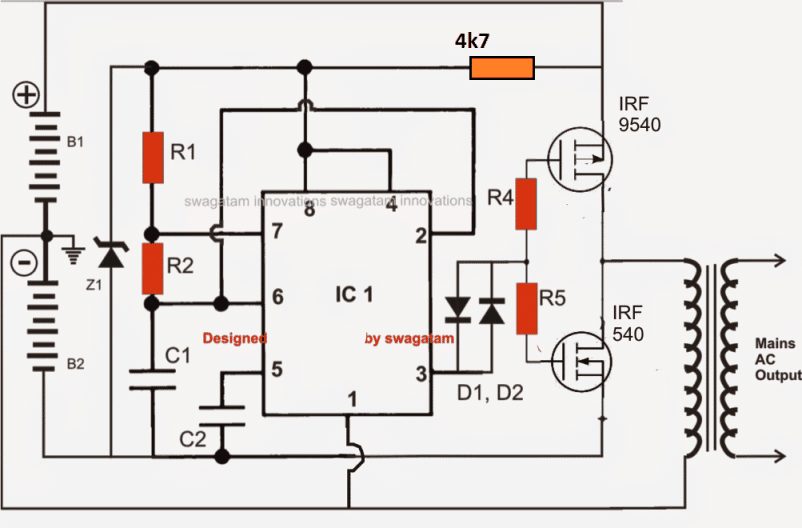
The circuit of a simplest full bridge power inverter explained requires a single IC 555, a couple of the mosfets and a power transformer as the top ingredients.
As shown in the figure, the IC 555 has been wired as usual in the an astable multivibrator form. The resistors R1 and R2 decides the duty cycle of the inverter.
R1 and R2 must be adjusted and calculated precisely for getting a 50% duty cycle, otherwise the inverter output may generate unequal waveform, which may lead to unbalanced AC output, dangerous for the appliances and also the mosfets will tend to dissipate unevenly giving rise to multiple issues in the circuit.
The value of the C1 must be chosen such that the output frequency comes to about 50 Hz for 220V specs and 60 Hz for 120V specs.
The mosfets can be any power mosfets, capable of handling huge currents, may be upto 10 amps or more.
Here since the operation is a full bridge type without any full bridge driver ICs, two batteries are incorporated instead of one for supplying the ground potential for the transformer and in order to make the transformer secondary winding responsive to both positive and negative cycles from the mosfet operations.
The idea has been designed by me, however it has not been yet tested practically so kindly take this issue into consideration while making it.
Assumably the inverter should be able to handle upto 200 watts of power easily with great efficiency.
The output will be a square wave type.
Parts List
- R1 and R2 = See Text,
- C1 = See text,
- C2 = 0.01uF
- R3 = 470 Ohms, 1 watt,
- R4, R5 = 100 Ohms,
- D1, D2 = 1N4148
- Mosfets = see text.
- Z1 = 5.1V 1 watt zener diode.
- Transformer = Asper power requirement,
- B1, B2 = two 12 volts batteries, AH will be as per preference.
- IC1 = 555
Another Full Bridge 555 Inverter
Another full bridge 555 inverter using a 2 wire transformer is shown in the following diagram. Unlike the above design this inverter does not depend on two batteries rather works with a single battery.
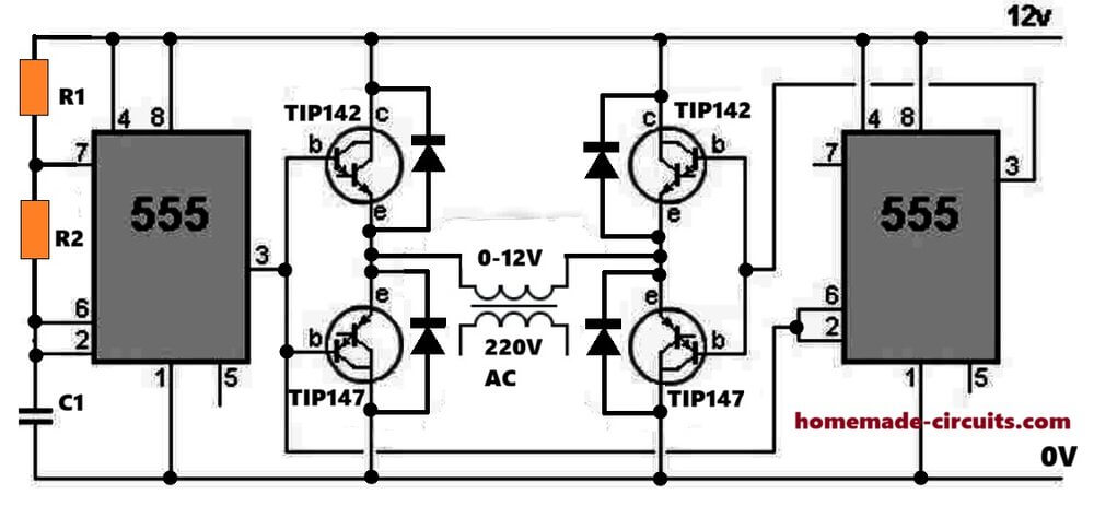
The IC 555 again is rigged as a simple astable multivibrator circuit whose output frequency can be adjusted to a precise 50 Hz or 60 Hz using a this calculator tool.
The frequency is fed to push pull power transistor network using TIP122 and TIP127 configuration, which provides a high current oscillation into the connected power transformer.
A series resistor/inductor network using C4 and L1 ensure an over current protection for the transistors, and allows a controlled running of the full bridge inverter.
The transformer can any ordinary step-down transformer such as 12-0-12V/5 amp, if the supply voltage is 15V. Alternatively a 9-0-9V transformer can be also tried for a 12V battery operation.
Pats List
| Component | Description / Value JPG |
| IC1, IC2 | 555 Timer integrated circuit |
| Q1, Q2, Q3, Q4 | TIP142 NPN Darlington transistor |
| Q5, Q6, Q7, Q8 | TIP147 PNP Darlington transistor |
| R1, R2 | Resistors (timing network) |
| C1 | Capacitor (timing network) |
| Diodes | Flyback / protection diodes across each transistor |
| Transformer | Mains transformer with center-tapped secondary (0-12V primary/secondary configuration to 220V AC) |
Simple Full Bridge 555 Inverter using Two Transistors
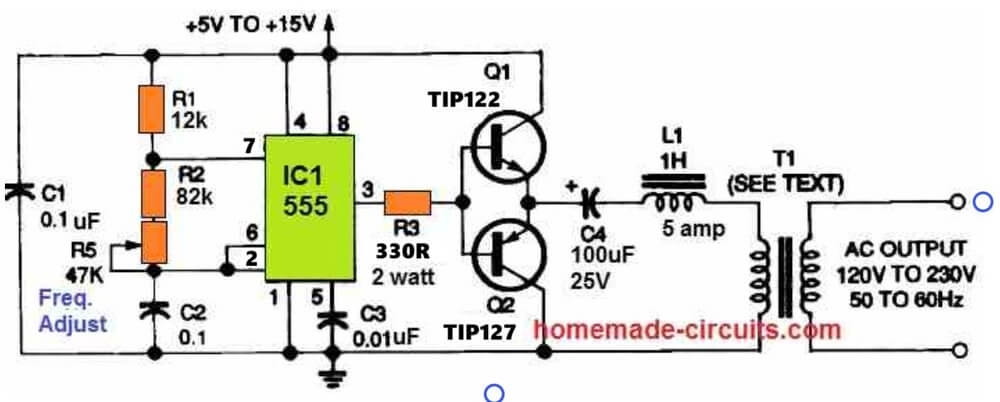
This IC 555 inverter circuit uses a timer IC to generate switching pulses which are then used to drive a pair of power transistors, TIP122 and TIP127. These transistors are connected to a transformer through an inductor and a capacitor with the aim of converting DC power into AC power.
The circuit is designed to operate from a supply of +5V to +15V. The 47K preset is provided for adjusting the oscillator frequency, so we can change the timing of the pulses generated by the IC 555.
The IC 555 works as an astable oscillator. The resistors R1 and R2 along with the 47K preset and capacitor C2 gives us the oscillator timing. The output pulses are available from pin 3 of the IC and are fed to the transistor stage through resistor R3.
The TIP122 and TIP127 are complementary Darlington transistors. They are positioned to handle the current required by the output stage, but the way they are connected in this diagram needs careful checking before we can confirm that the circuit will work properly.
The capacitor C4 is connected in series with the transformer and is positioned to pass the changing signal along with blocking steady DC. The inductor L1 is also connected in series with the output path and may be used to help with current control or waveform shaping.
The transformer T1 is intended to step up the voltage and provide an AC output of around 120V to 230V at 50 to 60Hz, depending on the transformer and operating conditions.
Parts List
| No. | Component | Value / Part number | Quantity |
|---|---|---|---|
| 1 | Timer IC | NE555 / IC 555 | 1 |
| 2 | NPN Darlington transistor | TIP122 | 1 |
| 3 | PNP Darlington transistor | TIP127 | 1 |
| 4 | Resistor R1 | 1KΩ | 1 |
| 5 | Resistor R2 | 10KΩ | 1 |
| 6 | Preset resistor | 47KΩ | 1 |
| 7 | Resistor R3 | 1KΩ | 1 |
| 8 | Resistor R4 | 1KΩ | 1 |
| 9 | Capacitor C1 | 0.1µF | 1 |
| 10 | Capacitor C2 | 0.01µF | 1 |
| 11 | Capacitor C3 | 100µF | 1 |
| 12 | Capacitor C4 | 10µF | 1 |
| 13 | Inductor L1 | Value not specified in the diagram | 1 |
| 14 | Transformer T1 | Suitable step-up transformer; exact rating not specified | 1 |
| 15 | DC power supply | +5V to +15V, as indicated | 1 |


Need Help? Please Leave a Comment! We value your input—Kindly keep it relevant to the above topic!