In this post I have explained a simple 48V inverter circuit which may be rated at as high as 2 KVA. The entire design is configured around a single IC 4047 and a few power transistors.
Technical Specifications
I am a big fan of u....i am a wisp. i need an inverter design with 48volt DC input and 230volt output supply and output power in the range up to 500w.
This inverter will be running 24*7*365 days continuously and should not have charging facility. will u please design the circuit and transformer running on 48v.
Thanks & Regards
Circuit Diagram
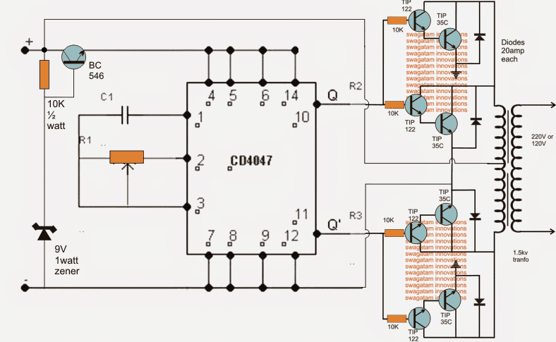
Circuit Description
Referring to the shown 48V inverter circuit, the IC 4047 forms the main oscillator stage responsible of producing a totem pole outputs for the connected output stage.
The output stage is made by configuring a 4 individual high gain high power transistors modules, two of them on each channel of the push pull output stage.
The TIP122 are themselves internally configured as Darlingtons which are further attached with TIP35 transistor in the Darlington for generating exceptionally powerful current gain across each of the modules.
Setting up the Oscillator Frequency
C1 and R1 must be appropriately set for achieving the desired frequency as per the required specifications...could be 50 Hz or 60 Hz.
The shown 48 V inverter configuration is designed to generate a massive 2 kva of output power provided the devices are mounted on sufficiently large heatsinks and the battery rated at 48 V, 100 AH, also the transformer rated at 36-0-36V, 1 kva
For lower outputs, one of the modules could be eliminated from each of the channels.
The BJT BC546 is positioned to provide a reasonably fixed 9 V to the IC in order to keep the IC safe from the high battery voltage and within its specified working voltage limit.
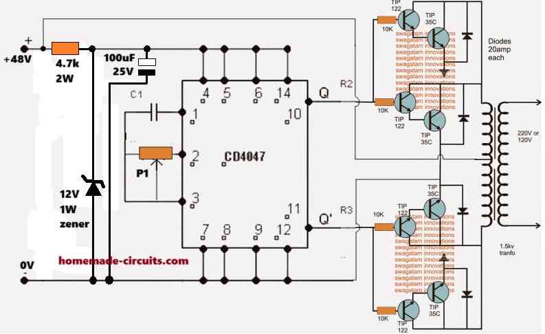
Using Zener Diode to Drop Regulate the IC supply Voltage
In the above explained 48V inverter circuit I have used a BC546 emitter-follower series pass circuit to step down the 48V DC to 9V DC for supplying the IC 4047.
However, if the BC546 transistor is not available, we can incorporate a zener/resistor based regulator for achieving the same results, as shown in the following diagram:


Questions & Answers
I WANT TO MAKE A INVERTER INPUT VOLT IS 48 DC TO OUT PUT 220 AC USE LITHIUM PHOSPHATE BATTERY.CAN EXPLAIN WITH DIAGRAM?
What should be the waveform, sine or square?
I want this sinewave
You can upgrade it to sine wave using the following concept: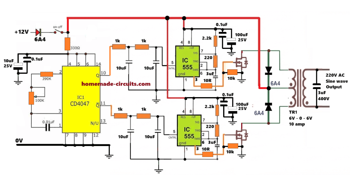
Good morning. Am your fan from Nigeria. My name is Mr Justice. Please I do I make a pure sin wave 24v to 220v inverter from home. Please assist me.
You are welcome justice…you can try the 3rd schematic rom the following article, let me know if you have any doubts regarding its construction…
https://www.homemade-circuits.com/pure-sine-wave-inverter-circuit-using/
please sir,kind you kindly assist me with a very simple inverter circuit without ic that can power my 21inch plasm tv.Am you fans from African Nigeria in particular.
Hi Abubakar, You can try the first diagram from the following article. Make sure to use a 9-0-9V 10 amp transformer, and a 12V 50 Ah battery, and connect a 3uF/400V PPC capacitor across the AC output wires of the transformer.
https://www.homemade-circuits.com/7-simple-inverter-circuits/
pls how can I convert a 48vdc to 12vdc for my inverter oscillator because BC 546 is not in my area pls any alternative way with diagram
I have updated the new diagram at the end of the above article, which uses a zener diode based voltage regulator, please check it.
Sir can I use 22k variable
Hello Nnakwuzie, For R1 you can use a 100k preset.
Good day Sir,
Thanks for this simple circuit.
Please for a 12V to 230V, pure sine wave version.
Using same IC and transistors.
Thanks
Thank you Ngang, you can try the following concept:
https://www.homemade-circuits.com/pure-sine-wave-inverter-circuit-using/
Thank you for sharing the circuits. Is there a design for a pure sine wave cct board to retrofit into a 48V dc to 220Vac inverter? This particular unit (from 97) uses 2x SANREX QBB100A60 modules.
It is difficult to get a universal inverter module, because all inverters have different design layouts and specifications.
Dear Sir,
I do not understand the primary part of transformer circuit. Obviously very large AC current will flow through primary coil. How I know that secondary Voltage will be 230V or else, considering that it depends on frequency and the amplitude of the current in the primary circuit. More simply, how I can tune output voltage eg. to be 130 or 230V.
Thanks in advance,
Regards
Vito..
Hi Vito, the output or the secondary voltage of an inverter depends on the switching primary voltage of the transformer, and also the rating of the transformer. To get 230 V at the output, your transformer secondary must be rated at 230V or 220V, and the primary of the transformer must be switched at a voltage level which matches the primary side voltage rating.
Dear Swagatam,
Thank you very very much! I am a physicist but I am quite new to this field.
One thing more I think do not understand.
In the collector circuit there is no any resistor whether that means the the primary coil itself is understood as resistance??
Thanks
Vito..
Thank you Dear Vito,
Yes, the transformer primary coils itself work as the collector load. If a resistance is added then current to the transformer winding will drop and the inverter output will be weak and cannot handle AC loads.
Dear Swagatam,
Thank you very much. I think now I understand the operation of the circuit. I will try to construct it.
Best regards
Vito.
You are most welcome Vito.
Good day Swagatam, I just completed my BS in electronics engineering, and I have a suggestion. I am planning to setup a 4kW solar panel system, and I plan to use 10, 400W solar panel. Each panel is 48V and 8A max. I will need an inverter with input 480V DC with 8 amps input to convert to 240V AC with 16A, or an inverter with 48V and 80 amps input to convert to 240V AC with 16A. Which you believe is easier to design based on the parts available. Thanks in advance for your response.
Hello Gamal, yes the 48V option appears to be a more workable option
You can probably try the following concept by suitably increasing the number of mosfets in parallel.
You will have to disconnect the drains of the p channel mosfets from the 12V line and connect them to the +48V line. Also make sure that the supply does not go beyond the 48V mark
The oscillator circuit will need to be fed separately from a 12V step down supply input
https://www.homemade-circuits.com/easy-h-bridge-mosfet-driver-circuit-for-inverters-and-motors/
Hello sir Swagatam,any changes to the circuitry if I was to make a 12v,24v and 36v (5000w)inverter? Again sir,is the setup for a pure sine wave? If yes what are the wave forms? Any images will appreciate, thanks.
Hi Evans, for 12V you can eliminate the BC546 stage and use the 12V directly for the entire circuit. For 24V and 36V you can use the same design.
How much whole arrangement will cost. And where it is available??
You will have to make it by buying the parts from the market…..
Can anyone direct me to a store where can i find the transformer 36-0-36v 1kv.
Thanks
200 vA 48V inverter circuit digram and transformer data That i need please
Hello swagatham,
I trued irfp240 one pair for a 300w transformer ofwith 48-0-48 primary, but it’s heating up and working at just half the power when I tested it with a 60w bulb, what could be the solution?
Hello Rajiv, Please use IRF540, two in parallel for each channel, and on large heatsink.
make sure to connect a 100uF/100V across the supply terminals of the IC. And I hope you have used the BC546 stage for dropping the supply to the IC
Sir,do you mind sending me an updated circuit using irF1010,for a 12v and 24v inverter intended to output 2000w? I would really appreciate.
Evans, I will try to update the mosfet design soon, with sine wave output
Good day,
Do you have an inverter with feedback, I want to use arduino to add feedback to my arduino inverter.
Good day, I do not have an Arduino based feedback system, but an universal Op amp based design is explained in the following article, which cuts off the MOSFETs when an overvoltage is detected
https://www.homemade-circuits.com/load-independentoutput-corrected/
May you kindly assist with a design for 230V AC to 48V 3Amps DC charger circuit with auto cutoff or even simple conversion circuit.
Thank you.
You can try this
https://www.homemade-circuits.com/make-this-48v-automatic-battery-charger/
which are the values of c1 and r1 for 50hz
Tks
you can try 68K and 0.1uF
May you kindly assist with a design for 48V DC to 240V AC converter .
The 48V DC must be supplied by a battery that is solar powered.
Thank you.
Thanks, Swagatam, any idea to make it Pure Sine wane ?
Hi Vhafuwi, you will have to chop the transistor base frequency with SPWM just as we did in this post for creating a sinewave!
https://www.homemade-circuits.com/pure-sine-wave-inverter-circuit-using/
I used CD 4047IC,got 6VAC on pins 10& 11 ,fed it to IRF540 mosfets it drastically drops to around 2VAC and I need 12VAC to be stepped up. What can I do to get 12VAC?
at pin10/11 it will show 6V for a 12V battery (50% duty cycle)….where does it show 2V? where do you want have 12V? Please explain with proper details.