• Skip to main content
  • Skip to primary sidebar

Homemade Circuit Projects

Need circuit help? Post them in the comments! I've answered over 50,000!

Blog | Categories | About | Hire Me | Contact | Calculators-online
You are here: Home / Inverter Circuits / 6 Best IC 555 Inverter Circuits Explored

6 Best IC 555 Inverter Circuits Explored

Last Updated on October 26, 2023 by Swagatam 224 Comments

The 6 unique designs below explains us how an ordinary single IC 555 astable multivibrator could be used effectively to make an inverter without involving complex stages.

Table of Contents
  • The Basic Design
  • How it Works
    • The Function of BC547
    • How the Transformer Works
      • The Importance of the Reverse Protection Diodes
    • Technical Specifications:
    • How to Calculate IC 555 Frequency
      • Video Clip:
      • Using BJT instead of MOSFETs
  • 2) IC 555 Full Bridge Inverter Circuit
    • How it Works
      • Parts List
    • Another Full Bridge 555 Inverter
  • 3) Pure Sine wave SPWM IC 555 Inverter Circuit
    • How the Circuit Functions – The PWM Stage
    • Integrating PWM with the Output Stage
      • Waveform Images:
    • 4) Another Sine wave Version using IC 555
    • Using IC 555 for the Inverter
      • Using IC 741 for the SPWM
  • 5) Transformerless IC 555 Inverter
  • 6) IC 555 Inverter with Automatic Arduino Battery Charger
    • Introduction
    • How the Circuits Works
      • Program for the Battery Cut Off:

No doubt IC 555 is a versatile IC which has many applications in the electronic world. However when it comes to inverters, IC 555 becomes ideally suitable for it.

In this post we'll discuss 5 outstanding IC 555 inverter circuits, from a simple square wave variant to slightly more advanced SPWM sinewave designs, and finally a full fledged ferrite core based DC to DC pwm inverter circuit. Let's begin.

The idea was requested by Mr. ningrat_edan.

The Basic Design

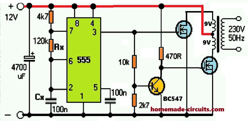
Referring to the shown diagram, a single IC 555 can be seen configured in its standard astable mode, wherein its pin#3 is used as the oscillator source for implementing the inverter function.

simple center IC 555 inverter circuit

NOTE: Please replace the 1 nF capacitor with a 0.47 uF capacitor for optimizing 50 Hz at the output. It can be a polar or a non-polar.

How it Works

The working of this IC 555 inverter circuit can be understood with the following step wise analysis:

The IC 555 is configured in an astable multivibrator mode, which allows its pin#3 to switch a continuous high/low pulses at a particular frequency rate. This frequency rate depends on the values of the resistors and capacitor across its pin#7, Pin#6, 2 etc.

Pin#3 of the IC 555 generates the required 50 Hz or 60 Hz frequency for the MOSFETs.

As we know that the MOSFETs here are required to run alternately for enabling a push-pull oscillation on the attached transformer center tap winding.

Therefore both the MOSFET gates cannot be connected to pin#3 of the IC. If we do this both the MOSFETs would conduct simultaneously causing both the primary winding to switch together. This would cause two anti-phase signals induced at the secondary causing a short circuit of the output AC and there would be a a net zero AC at the output, and heating up of the transformer.

To avoid this situation, the two MOSFETs needs to be operated alternately in tandem.

The Function of BC547

To ensure that the MOSFETs switch alternately at 50 Hz frequency from pin#3 of the IC 555, we introduce a BC547 stage for inverting the pin#3 output across its collector.

By doing this we effcetively enable the pin#3 pulse to create opposite +/- frequencies, one at pin#3 and the other at the collector of the BC547.

With this arrangement, one MOSFET gate operate from pin#3, while the other MOSFET operates from the collector of the BC547.

This means when MOSFET at pin#3 is ON, MOSFET at the BC547 collector is OFF, and vice versa.

This effectively allows the MOSFETs to switch alternately for the required push pull switching.

How the Transformer Works

The working of the transformer in this IC 555 inverter circuit can be learned from the following explanation:

When the MOSFETs conduct alternately, the relevant half winding is supplied with the high current from the battery.

The response allows the transformer to generate a push pull switching across its center tap winding. The effect of this causes the required 50 Hz alternating current or the 220 V AC to be induced across its secondary winding

During the ON periods the respective winding store energy in the form electromagnetic energy. When the MOSFETs are switches OFF the relevant winding kicks back its stored energy on the secondary mains winding inducing the 220V or 120V cycle on the output side of the transformer.

This keeps happening alternately for the two primary winding causing an alternating 220V/120V mains voltage to develop on the secondary side.

The Importance of the Reverse Protection Diodes

This type of center tap topology has a downside. When the primary half winding throws the reverse EMF, this is also subjected on the MOSFET drain/source terminals.

This can have a devastating effect on the MOSFETs if the reverse protection diodes are not included across the primary side of the transformer. But including these diodes also means precious energy being shunted to ground, causing the inverter to work with a lower efficiency.

Technical Specifications:

  • Power Output: Unlimited, can be between 100 watt to 5000 watts
  • Transformer: As per preference, Wattage will be as per the Output Load wattage requirement
  • Battery: 12V, and Ah rating should be 10 times more than the current selected for the transformer.
  • Waveform: Square Wave
  • Frequency: 50 Hz, or 60 Hz as per country code.
  • Output Voltage: 220V or 120V as per country code

How to Calculate IC 555 Frequency

The frequency of  IC 555 astable oscillator circuit is basically determined by an RC (resistor, capacitor) network configured across its pin#7, pin#2/6 and ground.

When IC 555 is applied as an inverter circuit, the values of these resistors and the capacitor is calculated such that the pin#3 of rthe IC produces a frequency of either around 50Hz, or 60 Hz. 50 Hz is the standard value compatible for 220V AC output while 60Hz is recommended for 120V AC outputs.

The formula for calculating the RC values in a IC 555 circuit is shown below:

F = 1.44 / (R1 + 2 x R2) C

Where F is the intended frequency output, R1 is the resistor which is connected between  pin#7 and ground in the circuit, while R2 is the resistor in between pin#7 and pin#6/2 of the IC. C is the capacitor found between pin#6/2 and ground.

Remember F will be in Farads, F will be in Hertz, R will be in Ohms, and C will be in microFarads (μF)

Video Clip:

Waveform Image:

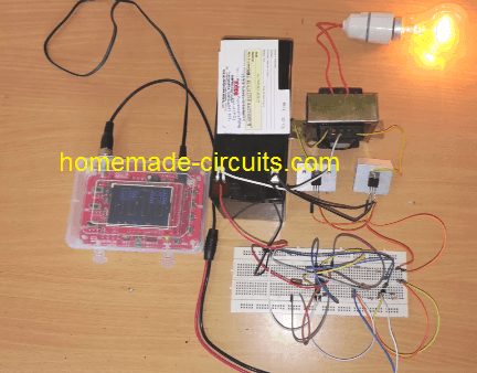
IC 555 inverter waveform image

Using BJT instead of MOSFETs

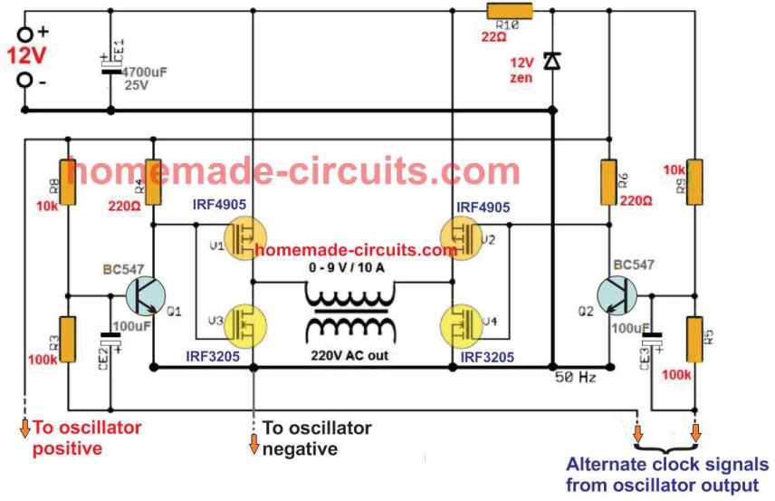
In the above diagram we studied a MOSFET based inverter with center tap transformer. The design made use of 4 transistor in all which appears to be a bit lengthy and less cost effective.

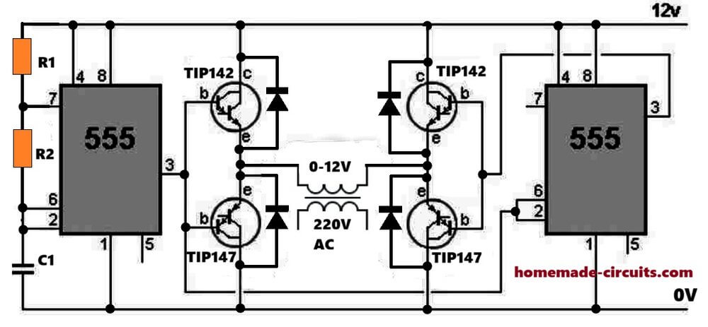
For hobbyists who may be interested in building a IC 555 inverter using a couple of power BJTs only will find the following circuit very useful:

IC 555 inverter circuit using just two transistors
NOTE: The transistors are wrongly shown as TIP147, which are actually TIP142

UPDATE: Did you know, you could make a cool modified sine wave inverter simply by combining a IC 555 with IC 4017, see the second diagram from this article: Recommended for all dedicated inverter hobbyists


2) IC 555 Full Bridge Inverter Circuit

The idea presented belowcan be considered as the simplest IC 555 based full bridge inverter circuit which is not only simple and cheap to build but is also significantly powerful. The power of the inverter may be increased to any reasonable limits y suitably modifying the number of mosfets at the output stage.

How it Works

The circuit of a simplest full bridge power inverter explained requires a single IC 555, a couple of the mosfets and a power transformer as the top ingredients.

As shown in the figure, the IC 555 has been wired as usual in the an astable multivibrator form. The resistors R1 and R2 decides the duty cycle of the inverter.

R1 and R2 must be adjusted and calculated precisely for getting a 50% duty cycle, otherwise the inverter output may generate unequal waveform, which may lead to unbalanced AC output, dangerous for the appliances and also the mosfets will tend to dissipate unevenly giving rise to multiple issues in the circuit.

The value of the C1 must be chosen such that the output frequency comes to about 50 Hz for 220V specs and 60 Hz for 120V specs.

The mosfets can be any power mosfets, capable of handling huge currents, may be upto 10 amps or more.

Here since the operation is a full bridge type without any full bridge driver ICs, two batteries are incorporated instead of one for supplying the ground potential for the transformer and in order to make the transformer secondary winding responsive to both positive and negative cycles from the mosfet operations.

The idea has been designed by me, however it has not been yet tested practically so kindly take this issue into consideration while making it.

Assumably the inverter should be able to handle upto 200 watts of power easily with great efficiency.

The output will be a square wave type.

IC 555 full bridge inverter using 2 batteries

Parts List

  • R1 and R2 = See Text,
  • C1 = See text,
  • C2 = 0.01uF
  • R3 = 470 Ohms, 1 watt,
  • R4, R5 = 100 Ohms,
  • D1, D2 = 1N4148
  • Mosfets = see text.
  • Z1 = 5.1V 1 watt zener diode.
  • Transformer = Asper power requirement,
  • B1, B2 = two 12 volts batteries, AH will be as per preference.
  • IC1 = 555

Another Full Bridge 555 Inverter

Another full bridge 555 inverter using a 2 wire transformer is shown in the following diagram. Unlike the above design this inverter does not depend on two batteries rather works with a single battery.

The IC 555 again is rigged as a simple astable multivibrator circuit whose output frequency can be adjusted to a precise 50 Hz or 60 Hz. The frequency is fed to push pull power transistor network using TIP35 and TIP36 configuration, which provides a high current oscillation into the connected power transformer.

A series resistor/inductor network using C4 and L1 ensure an over current protection for the transistors, and allows a controlled running of the full bridge inverter.

The transformer can any ordinary step-down transformer such as 12-0-12V/5 amp, if the supply voltage is 15V. Alternatively a 9-0-9V transformer can be also tried for a 12V battery operation.

3) Pure Sine wave SPWM IC 555 Inverter Circuit

The proposed IC 555 based pure sine wave inverter circuit generates accurately spaced PWM pulses which imitates a sine wave very closely and thus can be considered as good as its sine wave counter part design.

Here we use  two stages for creating the required  PWM pulses, the stage comprising the ICs 741 and the other comprising the IC 555. Let’s learn the whole concept in details.

How the Circuit Functions – The PWM Stage

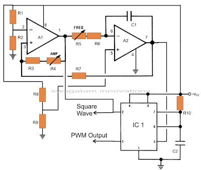
opamp TL072 based square wave and triangle wave modulation generator for IC 555

The circuit diagram can be understood with the following points:

The two opamps are basically arranged to generate the required sample source voltages for the IC 555.
The couple of outputs from this stage is responsible for the generation of square waves and triangular waves.

The second stage which is actually the heart of the circuit consists of the IC 555. Here the IC is wired in a monostable mode with the square waves from the opamp stage applied to its trigger pin #2 and the triangular waves applied to its control voltage pin # 5.

The square wave input triggers the monostable to generate a chain of pulses at the output where as the triangular signal modulates the width of this output square wave pulses.

The output from the IC 555 now follows the “instructions” from the opamp stage and optimizes its output in response to the two input signals, producing the sine equivalent PWM pulses.

Now it’s just a matter of appropriately feeding the PWM pulses to the output stages of an inverter consisting of the output devices, the transformer and the battery.

Integrating PWM with the Output Stage

Power transistor and transformer stage for sine wave IC 555 inverter circuit

The above PWM output is applied to the output stage as shown in the figure.

Transistors T1 and T2 receive the PWM pulses at their bases and switch the battery voltage into the transformer winding according to the duty cycles of the PWM optimized waveform.

The other two transistors make sure that the conduction of T1 and T2 takes place in tandem, that is alternately so tat the output o from the transformer generates one complete AC cycle with the two halves of the PWM pulses.

Waveform Images:

IC 555 sinewave inverter waveform

(Courtesy: Mr. Robin Peter)

Please also see this 500 VA modified sine wave design, developed by me.

Parts List for the above IC 555 pure sine wave inverter circuit

  • R1, R2, R3, R8, R9, R10 = 10K,
  • R7 = 8K2,
  • R11, R14, R15, R16 = 1K,
  • R12, R13 = 33 Ohms 5 Watt,
  • R4 = 1M preset,
  • R5 = 150 K preset,
  • R6 = 1K5
  • C1 = 0.1 uF,
  • C2 = 100 pF,
  • IC1 = TL 072,
  • IC2 = 555,
  • T1, T2 = BDY29,
  • T5, T6 = TIP 127,
  • T3, T4 = TIP122
  • Transformer = 12 – 0 – 12 V, 200 Watts,
  • Battery = 12 volts, 100 AH.
  • IC 555 Pinout
IC 555 pinout details

IC TL072 Pinout Details

IC TL072 pinout details

SPWM waveform stands for sinewave pulse width modulation waveform and this is applied in the discussed SPWM inverter circuit using a few 555 ICs and a single opamp.

4) Another Sine wave Version using IC 555

In one of my earlier posts we elaborately learned how to build a SPWM generator circuit using an opamp and two triangle wave inputs, in this post we use the same concept to generate the SPWMs and also learn the method of applying it within a IC 555 based inverter circuit.

IC 555 sine wave pwm inverter circuit

Using IC 555 for the Inverter

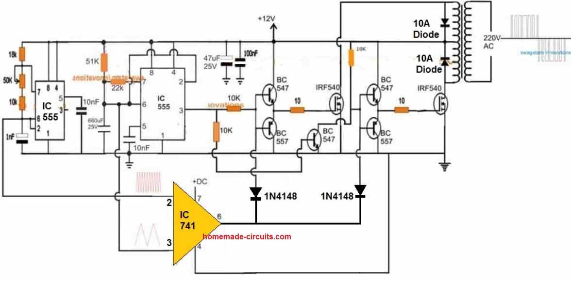
The diagram above shows the entire design of the proposed SPWM inverter circuit using IC 555, where the center IC 555 and the associated BJT/mosfet stages forms a basic square wave inverter circuit.

Our aim is to chop these 50Hz square waves into the required SPWM waveform using an opamp based circuit.

Therefore we accordingly configure a simple opamp comparator stage using the IC 741, as shown in the lower section of the diagram.

As already discussed in our past SPWM article, this opamp needs a couple of triangle wave sources across its two inputs in the form of a fast triangle wave on its pin#3 (non-inverting input) and a much slower triangle wave at its pin#2 (inverting input).

Using IC 741 for the SPWM

We achieve the above by using another IC 555 astable circuit which can be witnessed at the extreme left of the diagram, and use it for creating the required fast triangle waves, which is then applied to the pin#3 of the IC 741.

For the slow triangle waves we simple extract the same from the center IC 555 which is set at 50% duty cycle and its timing capacitor C is tweaked appropriately for getting a 50Hz frequency on its pin#3.

Deriving the slow triangle waves from the 50Hz/50% source ensures that the chopping of the SPWMs across the buffer BJTs is perfectly synchronized with the mosfet conduct ions, and this in turn ensures that the each of the square waves are perfectly "carved" as per the generated SPWM from the opamp output.

The above description clearly explains how to make a simple SPWM inverter circuit using IC 555 and IC 741, if you have any related queries please feel free to use the below given comment box for prompt replies.

5) Transformerless IC 555 Inverter

The design showing below depicts a simple yet very effective 4 MOSFET n channel full bridge IC 555 inverter circuit.

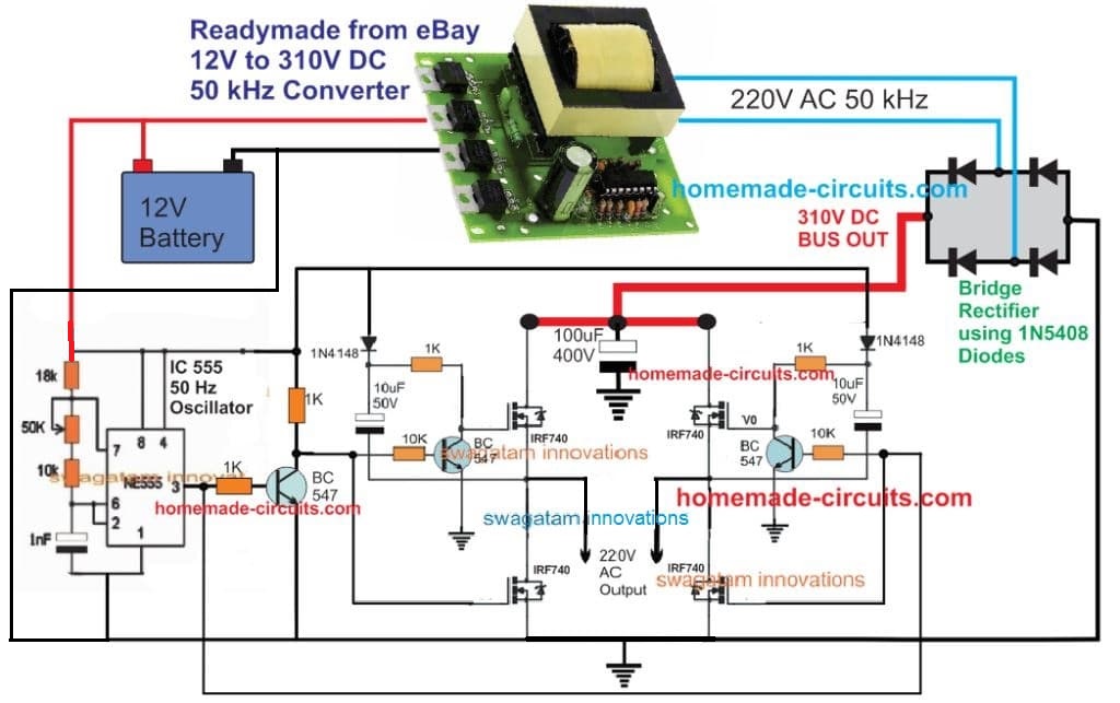
The 12 V DC from the battery is first converted into 310 V DC through a ready made DC to AC converter module.

This 310 VDC is applied to the MOSFET full bridge driver for converting it into a 220 V AC output.

The 4 N channel MOSFETs are appropriately bootstrapped using individual dide, capacitor and BC547 network.

The switching of the full bridge section is executed by the IC 555 oscillator stage. The frequency is around 50 Hz set by the 50 k preset at pin#7 of the IC 555.

4 n channel full bridge IC 555 inverter circuit

6) IC 555 Inverter with Automatic Arduino Battery Charger

In this 6th inverter design we use a 4017 decade counter and a ne555 timer Ic are used to generate a sinewave pwm signal for the inverter and an Arduino based automatic high/low battery cut-off with alarm.

By: Ainsworth Lynch

Introduction

In this circuit what actually happens is that the 4017 outputs a pwm signal from 2 of its 4 output pins which is then chopped up and if the proper output filtering is in place at the secondary side of the transformer it takes the shape or close enough to the shape of an actual sine wave form.

The first NE555 feeds a signal to pin 14 of the 4017 which is 4 times the required output frequency that you need since the 4017 switches across its 4 outputs, in other words if you need 60hz you would need to supply 4*60hz to pin 14 of the 4017 IC which is 240hz.

This circuit has an over voltage shutdown feature, under voltage shutdown feature and a low battery alarm feature all that is done by a microcontroller platform called the Arduino which needs to be programmed.

The program for the Arduino is straight forward and has been provided at the end of the article.

If you feel that you won’t be able to complete this project with the micro controller added it can be omitted and the circuit will work just the same.

How the Circuits Works

This IC 555 Inverter with Arduino Hi/Low Battery Shutdown Circuit can work from 12v, 24, and 48v going to 48v an appropriate version voltage regulator would have to be selected and the transformer sized accordingly also.

The Arduino can be powered with 7 to 12v or even 5v from a usb but for a circuit like this it would be good to power it from 12v as not to have any voltage drop on the digital output pins which is used to power a relay which turns on the Ic in the circuit and also a buzzer for low voltage alarm.

The Arduino will be used to read battery voltages and it only works from 5V DC so a voltage divider circuit is used I used a 100k and a 10k in my design and those values are plotted in the code that is programmed in the Arduino chip so you have to use the same values unless you made modification to the code or write a different code which can be done since the Arduino is an open source plat form and its cheap.

The Arduino board in this design is also connected up with an LCD display 16*2 to display battery voltage.

Below is the schematic for the circuit.

Program for the Battery Cut Off:

#include <LiquidCrystal.h>
LiquidCrystal lcd(7, 8, 9, 10, 11, 12);
int analogInput = 0;
float vout = 0.0;
float vin = 0.0;
float R1 = 100000.0; // resistance of R1 (100K) -see text!
float R2 = 10000.0; // resistance of R2 (10K) - see text!
int value = 0;
int battery = 8; // pin controlling relay
int buzzer =7;
void setup(){
pinMode(analogInput, INPUT);
pinMode(battery, OUTPUT);
pinMode(buzzer, OUTPUT);
lcd.begin(16, 2);
lcd.print("Battery Voltage");
}
void loop(){
// read the value at analog input
value = analogRead(analogInput);
vout = (value * 5.0) / 1024.0; // see text
vin = vout / (R2/(R1+R2));
if (vin<0.09){
vin=0.0;//statement to quash undesired reading !
}
if (vin<10.6) {
digitalWrite(battery, LOW);
}
else {
digitalWrite(battery, HIGH);
}
if (vin>14.4) {
digitalWrite(battery, LOW);
}
else {
digitalWrite(battery, HIGH);
}
if (vin<10.9)) {
digitalWrite(buzzer, HIGH)
else {
digitalWrite(buzzer, LOW
lcd.setCursor(0, 1);
lcd.print("INPUT V= ");
lcd.print(vin);
delay(500);
}

For more info you may feel free to express your queries through comments.

You'll also like:

  • inverter2Convert Audio Amplifier into Pure Sinewave Inverter
  • inverter to ups conversionHow to Convert an Inverter to an UPS
  • GTI with SCRsGrid-tie Inverter (GTI) Circuit Using SCR
  • universal H bridge mosfet driver compressedEasy H-Bridge MOSFET Driver Module for Inverters and Motors

Filed Under: Inverter Circuits Tagged With: 555, Best, Circuits, Explored, Inverter

About Swagatam

I am an electronics engineer and doing practical hands-on work from more than 15 years now. Building real circuits, testing them and also making PCB layouts by myself. I really love doing all these things like inventing something new, designing electronics and also helping other people like hobby guys who want to make their own cool circuits at home.

And that is the main reason why I started this website homemade-circuits.com, to share different types of circuit ideas..

If you are having any kind of doubt or question related to circuits then just write down your question in the comment box below, I am like always checking, so I guarantee I will reply you for sure!


Previous Post: « GSM Fire SMS Alert Project
Next Post: How to Make a Transformer Winding Counter Circuit »

Reader Interactions

Questions & Answers

Total Posts: 224
Newest Oldest
bashir abdulkadir
September 16, 2016 • 10 years ago #44648

Please sir what is the Watt of this inverter ?

Reply
SwagatamAdmin
September 16, 2016 • 10 years ago #44656

Will depend on the trafo wattage and the battery AH capacity.

Reply
bashir abdulkadir
September 16, 2016 • 10 years ago #44664

Please can u help me and tell me how may i know the transformer WATT because i have UPS transformer but i don't know it WATT?

Reply
SwagatamAdmin
September 17, 2016 • 10 years ago #44688

apply mains AC across its mains side and then using an AC ammeter measure the current directly across the other side wire ends…then multiply the reading with the voltage specification of those wires

Reply
Davis Kakumba
September 17, 2016 • 10 years ago #44686

hi swagatam for the first diagram what is the rating of the transformer

Reply
SwagatamAdmin
September 17, 2016 • 10 years ago #44701

Hi Davis, it can be as per your own desired specification….

Reply
bashir abdulkadir
September 17, 2016 • 10 years ago #44690

i am greatfull so much and i am very appritiate for your site

Reply
eric maduku
September 17, 2016 • 10 years ago #44696

pls sir, can you help me with the diagram of IC 4047 and fets 1kw diagram since thats the only ic i can get around. Thanks

Reply
SwagatamAdmin
September 17, 2016 • 10 years ago #44705

Eric, you can try the following design

https://www.homemade-circuits.com/2014/11/48-v-inverter-circuit.html

you can replace the BJTs with FETs, and use 100 ohm resistor with their gates

Reply
chucks ichoku
September 17, 2016 • 10 years ago #44710

sir what are the appliances does the circuit above will power ?

Reply
SwagatamAdmin
September 18, 2016 • 10 years ago #44730

It will power most of the equipment which use internal SMPS

Reply
chucks ichoku
September 17, 2016 • 10 years ago #44711

sir can the circuit above power a fan without a noise???

Reply
SwagatamAdmin
September 18, 2016 • 10 years ago #44728

you can connect a capacitor with the fan to reduce noise

Reply
chucks ichoku
September 17, 2016 • 10 years ago #44712

I av 12v 0 12v to 230v AC, will it work on the cirvuit above? sir

Reply
SwagatamAdmin
September 18, 2016 • 10 years ago #44729

yes ti will work

Reply
bashir abdulkadir
September 18, 2016 • 10 years ago #44731

sir can i connect the above circuit with 6-0-6 ? and how the watt be ?

Reply
SwagatamAdmin
September 19, 2016 • 10 years ago #44748

it can be used if the battery is also 6V

Reply
bashir abdulkadir
September 19, 2016 • 10 years ago #44753

I am using a simple transformer. When I press ctrl+E, but tell me that how can i calculate these values like primary inductance, secondary inductance etc. Can you suggest me some calculator for this purpose?. My requirements are below: primary voltage: 220V, 50Hz secondary voltage: 12V, 1A

Reply
SwagatamAdmin
September 19, 2016 • 10 years ago #44765

I have already discussed how to design an inverter transformer in this website, you can refer to that article. you can find it through the search box above or by Google search..

Reply
john omaba
September 19, 2016 • 10 years ago #44757

Is the citcuit square wave or sine wave? If square wave where to attach chopper to it and make it modified sine wave? Thanks

Reply
SwagatamAdmin
September 19, 2016 • 10 years ago #44771

it's square wave, add chopper to the bases of the NPN/PNP

Reply
chucks ichoku
September 19, 2016 • 10 years ago #44785

sir what is dis chopper all about. is it a circuit. if yes can u upload it, let me take a look at it. thanks

Reply
SwagatamAdmin
September 20, 2016 • 10 years ago #44795

you can learn the details here

https://www.homemade-circuits.com/2013/04/how-to-modify-square-wave-inverter-into.html

Reply
gogutu
September 23, 2016 • 10 years ago #44892

Domnule Swagatam Majumdar,va rog sa-mi spuneti daca acest invertor poate fi folosit la o pompa electronica pentru centrala termica,atunci cand reteaua de curent a cazut.pompa consuma 40w.daca nu ce modificari trebuie aduse.Scuze ca nu vorbesc engleza.pls raspundeti.tank you

Reply
SwagatamAdmin
September 23, 2016 • 10 years ago #44913

da, acesta poate fi folosit pentru orice aplicație preferată ca pe alegerea ta

Reply
chucks ichoku
September 23, 2016 • 10 years ago #44896

hello sir swagattam, I designed an inverter, it is working perfectly. but my problem is '' the heatsink ther was not fan connected to it and it is hot so much. I need an automatic fan circuit for cooling of the heatsink whenever it start heating the fan will automatically blowing, and whenever it stop heating the fan will automatically stop…. thanks

Reply
SwagatamAdmin
September 23, 2016 • 10 years ago #44917

hello chucks, you can try the following concept

https://www.homemade-circuits.com/2015/03/fan-speed-controller-for-heatsink.html

Reply
bashir abdulkadir
September 25, 2016 • 10 years ago #44994

Please Sir help me as you are doing to us. please guide me how i am going to calculate battery mAH . Assume that the battery is 12v 100mAH and connected with 500watt inverter if i connect 7 phone chager each is 6 watt and 9 watt CFL how many are hours may the battery's charging take before the it finish

Reply
SwagatamAdmin
September 25, 2016 • 10 years ago #45010

I guess you meant to say 100AH battery??

you simply have to divide the battery AH with the load current, and multiply the result with 0.6, that will give you the approx battery back up time.

Reply
bashir abdulkadir
September 25, 2016 • 10 years ago #45012

If i get u for example if my current is 9 watt and my battery is 100AH THE ANSWER IS 100/9=11.1*0.6=6.6 hours ??

Reply
SwagatamAdmin
September 25, 2016 • 10 years ago #45021

It should be load current, not load wattage….your procedure was correct but in place of 9 watt you must apply current.

current can be found by dividing 9 watt with load voltage.

Reply
bashir abdulkadir
September 25, 2016 • 10 years ago #45022

thank sir may GOD expand ur idea more again

Reply
bashir abdulkadir
September 25, 2016 • 10 years ago #45024

is current the same with amp?

Reply
bashir abdulkadir
September 25, 2016 • 10 years ago #45025

amps = 1W / 230V
= 0.004348A ??

Reply
SwagatamAdmin
September 26, 2016 • 10 years ago #45038

yes that's correct. current is measured in amps.

Reply
bashir abdulkadir
September 26, 2016 • 10 years ago #45045

thank u sir

Reply
bashir abdulkadir
September 26, 2016 • 10 years ago #45068

My another Qestion Sir, for instant if i want to modify an low watt inverter less said 50watt please what and what do i going to change or to add. may i going to change height voltage transformer or i am going to add more transistor in pararal please which one should i going to do??

Reply
SwagatamAdmin
September 27, 2016 • 10 years ago #45085

what modifications do you want to make??

Reply
ningrat_edan
September 26, 2016 • 10 years ago #45078

hello sir,
I'm very grateful you have deigned to answer my questions by posting an inverter circuit NE555 ic that works on ferrite transformer, I really hope you do not get bored if I will be asking a lot more about this circuit.
I pray that God bless your family

Reply
SwagatamAdmin
September 27, 2016 • 10 years ago #45092

You are welcome Ningrat!!you can feel free to post new comments

Reply
ningrat_edan
September 27, 2016 • 10 years ago #45096

Thank you sir,
I am having trouble finding diodes past 10 amperes, .. is there a best solution for it

Reply
SwagatamAdmin
September 28, 2016 • 10 years ago #45106

you can try 6A4 diodes, see if they work alright?

Reply
ningrat_edan
September 28, 2016 • 10 years ago #45111

sir, this circuit produces high frequency ac voltage 50kHz whether it can converted into low frequency ac voltage between 50Hz – 60Hz

Reply
SwagatamAdmin
September 28, 2016 • 10 years ago #45116

Ningrat, the Rt, Ct values in the second circuit determines the 50Hz frequency for the load.

you can get the formula in the datasheet of the IC

Reply
ningrat_edan
September 28, 2016 • 10 years ago #45118

if we change the value of Rt and Ct to get 50Hz whether it could be applied in the ferrite transformer?
I mean a string of additional output transformer that will turn into a 50Hz 50kHz frequency

Reply
SwagatamAdmin
September 28, 2016 • 10 years ago #45123

ferrite transformer is supposed to be connected with the first diagram which has 50 Khz frequency, the lower circuit needs to be set at 50 Hz….

the load or appliance can be directly connected the lower circuit mosfet.

the 50 khz from the top circuit is fed to the second circuit through the bridge rectifier

Reply
ningrat_edan
September 28, 2016 • 10 years ago #45130

if the output of the circuit is converted into a dc voltage using a diode bridge and then a dc voltage is converted back into an ac voltage what it could be?
series such as what can turn into a dc voltage low frequency ac voltage in this issue?

Reply
SwagatamAdmin
September 29, 2016 • 10 years ago #45134

ferrite core can be operated only with high frequency, that's why initially high frequency is used for stepping up the battery voltage to 220V and then it is converted back to low frequency for our home appliances.

Reply
ningrat_edan
September 30, 2016 • 10 years ago #45155

Sir,
series such as what is used for converting high frequency to low frequency

Reply
SwagatamAdmin
September 30, 2016 • 10 years ago #45165

the four mosfets are toggled at the low frequency 50 Hz for executing the 50 Hz AC on the load

Reply
View Older Comments

Need Help? Please Leave a Comment! We value your input—Kindly keep it relevant to the above topic! Cancel reply

Your email address will not be published. Required fields are marked *

Primary Sidebar


My Youtube Channel

Circuit Simulator

circuit simulator image


Subscribe to get New Circuits in your Email


Categories

  • Arduino Projects (95)
  • Audio and Amplifier Projects (134)
  • Automation Projects (18)
  • Automobile Electronics (103)
  • Battery Charger Circuits (88)
  • Datasheets and Components (109)
  • Electronics Theory (149)
  • Energy from Magnets and Earth (40)
  • Games and Sports Projects (11)
  • Grid and 3-Phase (20)
  • Health related Projects (27)
  • Home Electrical Circuits (13)
  • Indicator Circuits (16)
  • Inverter Circuits (100)
  • Lamps and Lights (162)
  • Meters and Testers (72)
  • Mini Projects (28)
  • Motor Controller (68)
  • Oscillator Circuits (28)
  • Pets and Pests (15)
  • Power Supply Circuits (91)
  • Remote Control Circuits (50)
  • Security and Alarm (65)
  • Sensors and Detectors (107)
  • SMPS and Converters (45)
  • Solar Controller Circuits (61)
  • Temperature Controllers (43)
  • Timer and Delay Relay (50)
  • Voltage Control and Protection (44)
  • Water Controller (37)
  • Wireless Circuits (31)


Other Links

  • Privacy Policy
  • Cookie Policy
  • Disclaimer
  • Copyright
  • Videos
  • Sitemap

People also Search

555 Circuits | 741 Circuits | LM324 Circuits | LM338 Circuits | 4017 Circuits | Ultrasonic Projects | SMPS Projects | Christmas Projects | MOSFETs | Radio Circuits | Laser Circuits | PIR Projects |


Recent Comments

  • Swagatam on DPDT Relay Working, Pinouts, Testing Explained
  • Swagatam on DPDT Relay Working, Pinouts, Testing Explained
  • Swagatam on Inverter LC Filter Calculator
  • Swagatam on Notch Filter Circuits with Design Details
  • Nare Mashiachidi on DPDT Relay Working, Pinouts, Testing Explained

Social Profiles

  • Twitter
  • YouTube
  • Instagram
  • Pinterest
  • My Facebook-Page
  • Stack Exchange
  • Linkedin

© 2026 · Swagatam Innovations