In this post I will explain a very basic 12V to 220V AC inverter design using IC 555 as the oscillator stage, for generating a 50Hz frequency to the MOSFET driver stage of the inverter. We have used a center tap transformer for this design which effectively converter the battery 12V into 220V AC 50 Hz output, which is actually gives a square waveform output....
Referring to the shown diagram, a single IC 555 can be seen configured in its standard astable mode, wherein its pin#3 is used as the oscillator source for implementing the inverter function.
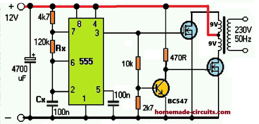
NOTE: Please replace the 1 nF capacitor with a 0.47 uF capacitor for optimizing 50 Hz at the output. It can be a polar or a non-polar.
Basic Overall Working
A standard 555 chip provides the 50Hz signal for this circuit. The values of resistor Rx and capacitor Cx set this frequency. Two N-channel MOSFETs work as switches to handle the power. One MOSFET connects straight to the 555 chip, and the second one gets its signal through a small BC547 transistor that behave like a inverter BJT. You need a regular mains transformer with two 9V secondary windings that can handle your maximum power load.
The two power MOSFETs might get hot, so you must fix them to a metal heatsink using insulator pads. If you use two separate heatsinks instead, then you do not need insulator pads but the heatsinks must never touch each other or the metal frame. Your 12V power supply must be strong enough and stay between 11V and 14V. Always put a fuse on the main power input line to stay safe.
If your electronics do not strictly need 50Hz then you can raise the frequency to around 100Hz to 300Hz by changing Rx and Cx. This helps lower the power used while idle. To change the output from 50Hz to 60Hz, you simply reduce the Rx resistor value by one-sixth, like dropping it from 120k to 100k.
For the power switches, use IRFZ44 for loads up to 200 watts, IRFZ48 up to 350 watts, or IRF3205 up to 600 watts. If you need more than 600 watts, then you can connect multiple IRF3205 transistors in parallel. The IRF1405 is also a very good option to use. This basic 555 inverter circuit gives an unregulated square wave output.
To avoid this situation, the two MOSFETs needs to be operated alternately in tandem.
The Function of BC547
To ensure that the MOSFETs switch alternately at 50 Hz frequency from pin#3 of the IC 555, we introduce a BC547 stage for inverting the pin#3 output across its collector.
By doing this we effcetively enable the pin#3 pulse to create opposite +/- frequencies, one at pin#3 and the other at the collector of the BC547.
With this arrangement, one MOSFET gate operate from pin#3, while the other MOSFET operates from the collector of the BC547.
This means when MOSFET at pin#3 is ON, MOSFET at the BC547 collector is OFF, and vice versa.
This effectively allows the MOSFETs to switch alternately for the required push pull switching.
How the Transformer Works
The working of the transformer in this IC 555 inverter circuit can be learned from the following explanation:
When the MOSFETs conduct alternately, the relevant half winding is supplied with the high current from the battery.
The response allows the transformer to generate a push pull switching across its center tap winding. The effect of this causes the required 50 Hz alternating current or the 220 V AC to be induced across its secondary winding
During the ON periods the respective winding store energy in the form electromagnetic energy. When the MOSFETs are switches OFF the relevant winding kicks back its stored energy on the secondary mains winding inducing the 220V or 120V cycle on the output side of the transformer.
This keeps happening alternately for the two primary winding causing an alternating 220V/120V mains voltage to develop on the secondary side.
The Importance of the Reverse Protection Diodes
This type of center tap topology has a downside. When the primary half winding throws the reverse EMF, this is also subjected on the MOSFET drain/source terminals.
This can have a devastating effect on the MOSFETs if the reverse protection diodes are not included across the primary side of the transformer. But including these diodes also means precious energy being shunted to ground, causing the inverter to work with a lower efficiency.
Technical Specifications:
- Power Output: Unlimited, can be between 100 watt to 5000 watts
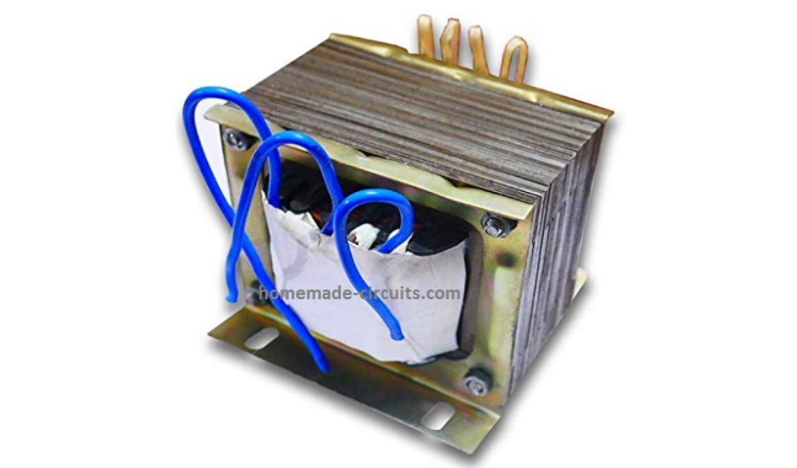
- Transformer: As per preference, Wattage will be as per the Output Load wattage requirement
- Battery: 12V, and Ah rating should be 10 times more than the current selected for the transformer.
- Waveform: Square Wave
- Frequency: 50 Hz, or 60 Hz as per country code.
- Output Voltage: 220V or 120V as per country code
How to Calculate IC 555 Frequency
The frequency of IC 555 astable oscillator circuit is basically determined by an RC (resistor, capacitor) network configured across its pin#7, pin#2/6 and ground.
When IC 555 is applied as an inverter circuit, the values of these resistors and the capacitor is calculated such that the pin#3 of rthe IC produces a frequency of either around 50Hz, or 60 Hz. 50 Hz is the standard value compatible for 220V AC output while 60Hz is recommended for 120V AC outputs.
The formula for calculating the RC values in a IC 555 circuit is shown below:
F = 1.44 / (R1 + 2 x R2) C
Where F is the intended frequency output, R1 is the resistor which is connected between pin#7 and ground in the circuit, while R2 is the resistor in between pin#7 and pin#6/2 of the IC. C is the capacitor found between pin#6/2 and ground.
Remember F will be in Farads, F will be in Hertz, R will be in Ohms, and C will be in microFarads (μF)
Video Clip:
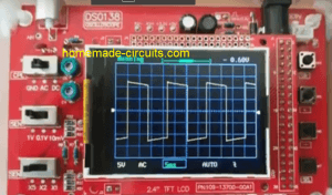
Waveform Image:
Using BJT instead of MOSFETs
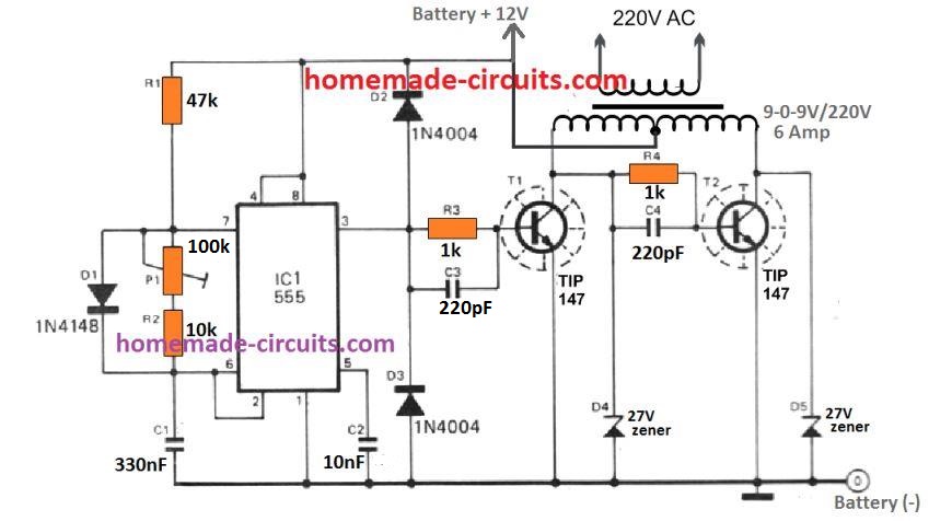
In the above diagram we studied a MOSFET based inverter with center tap transformer. The design made use of 4 transistor in all which appears to be a bit lengthy and less cost effective.
For hobbyists who may be interested in building a IC 555 inverter using a couple of power BJTs only will find the following circuit very useful:
UPDATE: Did you know, you could make a cool modified sine wave inverter simply by combining a IC 555 with IC 4017, see the second diagram from this article: Recommended for all dedicated inverter hobbyists


Need Help? Please Leave a Comment! We value your input—Kindly keep it relevant to the above topic!