In this post I have explained how to make a simple transformer winding counter circuit using ordinary LEDs and also through an advanced digital display circuit. The idea was requested by one of the dedicated readers of this blog
Circuit Objectives and Requirements
- I want a circuit which counts a number of turns for winding a transformer which is triggered by a magnetic reed switch.
- Actually i had made a wooden winding machine myself. now it is difficult to memorize the number of turns. that is why i have need it. it can show turns with the help of 7 segment displays or any easiest method. kindly made it.
- Another thing is that I am going to make a 5KV step type Voltage Regulator (Manual 8 to 9 steps) for
Home Purpose which diameter of wire should I use and what are the number of turns Primary as well as secondary. If possible Develop this circuit also.
The Design
The proposed transformer winding counter circuit can be easily built using a reed switch, a magnet, a few 4017 IC and LEDs, as shown below:
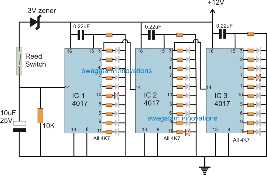
As can be seen in the above diagram, the reading for the winding count is simply achieved using LEDs across three IC 4017, this makes the assembly very straightforward and without any form special digital ICs or displays.
The idea is simple, the reed switch activates with every single rotation of the winding wheel which corresponds to a single turn count for the transformer winding.
This is indicated by the shifting or sequencing of the IC1 LED from its pin#3 to pin#11 constituting 10 winding count. This implies IC1 LEDs jump from one pin to another in response to each rotation of the wheel which corresponds to one winding turn.
Identically IC2 LEDs sequence in response to every 10 winding count, and therefore each shifting of LED from one pin to another indicates 10 winding count.
The IC3 is also configured to implement a similar sequencing but it responds to every 10 winding count which means its LEDs jump from one pin to another in response to every 100 winding count or 100 numbers turn on the transformer.
In short, IC1 LEDs output sequencing completes one cycle with every 10 winding, IC2 with every 100 winding and IC3 with every 1000 winding. Therefore the shown circuit has the limit of 1000 turn count, if more than this value is required then more IC stages could be added in the same manner as IC2 and IC3 are connected.
Digital Transformer Winding Counter Circuit
If the above discussed transformer winding counter circuit version looks low tech, one could employ the following high tech design which utilizes 7 segment common cathode displays for the indication.
The idea makes use of a few 4033 counter ICs cascaded together for obtaining a 4 digit output for indicating the number of turns counting in digital form.
Circuit Diagram
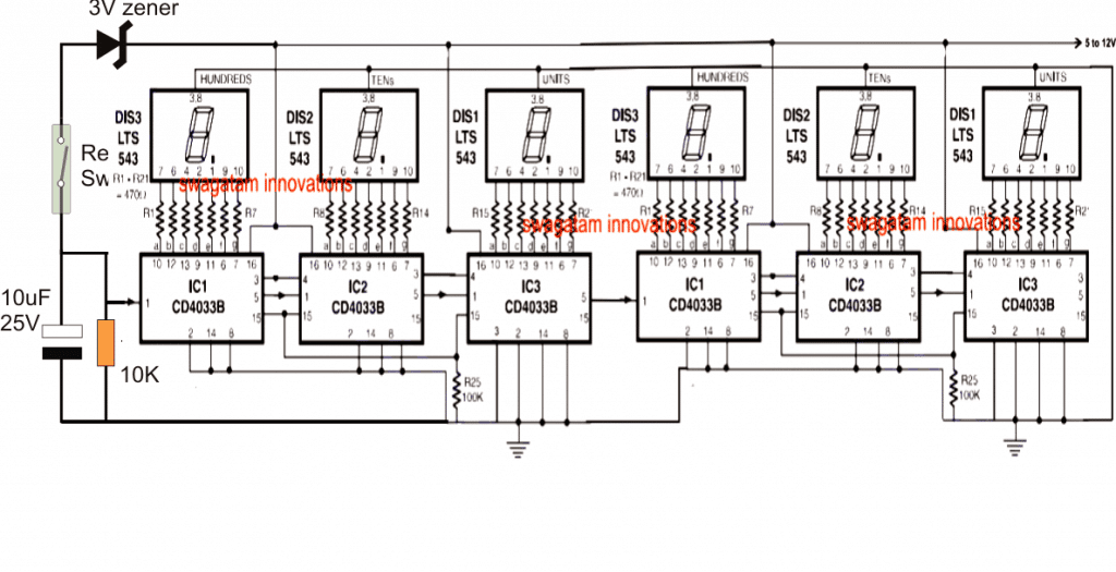
Here the reed switch and the associated parts remain identical to the previous LED version, and is rigged with the input of the 4033 counter module for the required triggering of the digits in response to each transformer winding count.


Questions & Answers
Sir were can I get those ics from
How do I make a digital readout coil counting machine that gives out how many turns it has completed. For a transformer.
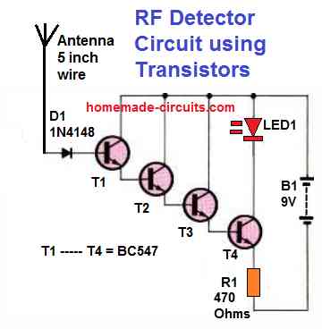
You can use the following circuit, and feed the frequency input terminal with the sensor output of the winder wheel. The sensor could be a hall effect sensor or a reed switch sensor.
https://www.homemade-circuits.com/5-digit-frequency-counter-circuit/
Good
The second circuit using 4033 is cool but I’m looking for programmable one. Eg if I need 100 turns I input 100 and the machine stop automatically at 100. Thanks in advance.
Glad you liked it, however this circuit is a analogue circuit so it cannot be programmed, looks difficult.
hi my dear 4033b pin3 this circuit are vss (-)so same other counter circuit pin3 are VDD(+)it is you are ok
Hi dear, you can check this article to know about the pinouts in details
https://www.homemade-circuits.com/ic-4033-pinouts-datasheet-application/
Thanks you i am follow you web sit very long yer
Sir, Can I use FND560 without change? Thank you
you are welcome!!
thank you. Very good your site, congratulations
Xavier, if it's a common cathode then it will work…
what is the range(count) of this circuit. why 6 no of led displays not 3 or 4
the shown LED illumination are just for example, practically the LEDs will light up sequentially depending on the instantaneous winding count
The above diagram shows red led in between other LEDs.for what purpose is it led and what is function of it
the bright LED signifies the illuminated LED among the 10 LEDs it's just an example to indicate how one of the LEDs will be seen illuminated at any instant during the sequential shifting of the LEDs across the 3 IC outputs.
Thanks very sir for the electronic tip I’m senet from Cameroon I’m still an absolute begginer, please for an example of a read switch in this appreciation