• Skip to main content
  • Skip to primary sidebar

Homemade Circuit Projects

Need circuit help? Post them in the comments! I've answered over 50,000!

Blog | Categories | About | Hire Me | Contact | Calculators-online
You are here: Home / Power Supply Circuits / Regulated, High Current Power Supply Circuit

Regulated, High Current Power Supply Circuit

Last Updated on July 13, 2024 by Swagatam 8 Comments

The circuit I have explained below can be used for applications that require stringent voltage regulations and ripple rejection criteria. The transistor pair are configured such that all residual ripple factor are perfectly rectified.

Table of Contents
  • Circuit Operation
    • Parts List

Circuit Operation

The circuit below shows a simple way of acquiring a perfectly regulated and stabilized high current DC voltage output using ordinary transistors.

The circuit is very simple to understand, let's study it with the following points:

This simple efficient high current 2N3055 based power supply is designed to handle in excess of 3 amp of currents, but must not exceed 5 amps.

The voltage that is required to be stabilized can be adjusted through R1 and the value of the zener diode.

The diodes at the input are arranged in a bridge network configuration for rectifying the voltage applied from the transformer.

C1 smoothens the DC further to feeds the filtered DC to the control circuit made up of Q1 and Q2.

R1 is introduced to start up the circuit by providing the required biasing to the transistor pair.

C2 makes sure that the transistor receive a perfectly smooth DC at their base without any ripples.

The zener diode at the base of the Q1 clamps the transistor with a fixed biasing voltage and inhibits any rise at the output voltage, irrespective of the voltage at the input.

Meaning even if the input voltage from the bridge network rises, the output remains unaffected and produces the voltage defined by the setting of R1 and the zener diode.
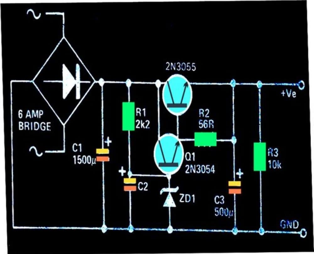
transistorized fixed voltage regulator circuit

Parts List

  • Resistors are 1/4 watt 1% MFR
  • 2.2 k, 10 k, 56 Ω = 1 each
  • Capacitors
  • Electrolytic 1500 µF / 50 V = 1
  • Electrolytic 500 µF / 50 v = 2
  • Semiconductors
  • Bridge Rectifier Diodes 6A4 = 4
  • Zener Diode 1 watt, voltage value as desired between 3 V to 30 V = 1
  • Transistors 2N3055, 2N3054 = 1 each
  • Large finned heatsink for the above transistors = 2
  • Transformer 0-15V, 5 amp = 1

You'll also like:

  • cheapestsmpscircuitCheapest SMPS Circuit Using MJE13005
  • ZEROTO220300VVARIABLEPOWERSUPPLYCIRCUIT0-300V Adjustable Transformerless Power Supply Circuit Diagram
  • lcdsmpscircuitLCD Monitor SMPS Circuit
  • smps2B3002Bwatt2Baudio2Bamp2Bpower2Bsupply2BcircuitSMPS 2 x 50V 350W Circuit for Audio Power Amplifiers

Filed Under: Power Supply Circuits Tagged With: Current, High, Power, Regulated, Supply

About Swagatam

I am an electronics engineer and doing practical hands-on work from more than 15 years now. Building real circuits, testing them and also making PCB layouts by myself. I really love doing all these things like inventing something new, designing electronics and also helping other people like hobby guys who want to make their own cool circuits at home.

And that is the main reason why I started this website homemade-circuits.com, to share different types of circuit ideas..

If you are having any kind of doubt or question related to circuits then just write down your question in the comment box below, I am like always checking, so I guarantee I will reply you for sure!

Previous Post: « AC Millivolts Meter Circuit Using IC 741
Next Post: Simple Bird Sound Generator Circuit »

Reader Interactions

Questions & Answers

Total Posts: 8
Newest Oldest
Andrii
December 12, 2025 • 10 months ago #195409

It would better to making a switching DC/DC converter – it has much better efficiency and not requires a heatsink .A couple of transistors (even one) may be used as amplifier error. As a PWM a Schmitt trigger with capacitor in feedback path may be used. A bipolar emitter follower (pnp and npn pairs) can amplify output current. A pulse transformer (with a ferrite core) and series capacitor may be used for drive the 2N3055 transistor – to matching impedances and save power.

Reply
SwagatamAdmin
December 13, 2025 • 10 months ago #195479

Yes, switching converters are always highly efficient and better than linear regulators…thanks for your feedback…

Reply
Carlos
March 16, 2024 • 3 years ago #150315

Hello, good afternoon, I like the circuit, but I want to know what function R 2 = 56 ohm fulfills. Thank you very much

Reply
SwagatamAdmin
March 16, 2024 • 3 years ago #150327

Hi, I think R2 is used to provide a stabilized feedback to the base of the pass transistor, to improve its conduction.

Reply
Nestor
November 1, 2022 • 4 years ago #134242

Could this circuit drive a 4 amps to a resistence of 0.8 ohms?

Reply
SwagatamAdmin
November 1, 2022 • 4 years ago #134251

If the 0.8 ohms load consumes 4 amps only, then yes, this circuit will work.

Reply
Ali mowahed
December 18, 2021 • 5 years ago #107605

Hello,
Here I am back at trying to understand the basics. I hooked up a Treadmill motor with the specs of 110VDC and 21A. 3HP to a simple bench power supply rated at 30V and 10A. As I turned the voltage knob on the power supply, even at hardly 2V, the motor began to spin, using hardly 1A.
My goal was to figure out the effect of and the relationship of voltage and amps. So I realized that Voltage seem to relate to the rotation of the armature and the Amperage relates to the load demand, which translates to torque. I assume horspower is along the same measurement as torque but I am not sure.

I also realized that the fan on the power supply would kick in more so in response to Amperage demand of the load than the turning it’s knob for more voltage.

So would I be correct to conclude that, looking at the specs of the motor. I assume that those specs means that the motor should not be connected to a power supply that is capable of supplying more than 110VDC along with more than 21A. And that you can supply it with more voltage so long as the supply will provide less amperage and vice versa that if the power supply provides more amps, it should provide less voltage. That is total combined of the two can not exceed the total of volts * amps, i.e. 110V*21A?

The rpm rating on the motor says 3200. Assuming the above conclusion of mine is correct, supplying more voltage correspond to more rotation on the motors armature, would this mean one can exceed the rpm rating of the motor beyond 3200? And that it is to be avoided or that the armature will not rotate any faster than that and will simply cause heat and other problems? Or that the motor might react the opposite and that with higher voltage its rpm will diminish aside from whatever else?

Furthermore, say for the above motor; if one had two choices for a power supply to it, one supplied higher voltage but less amps while the second provided less voltage but more amps, which one would be a safer choice?
I realize I brought up a quite few points, sorry about that.
Thank you in advance for any feedback.

Reply
SwagatamAdmin
December 18, 2021 • 5 years ago #107635

Hi,
The voltage decides the speed and the current decides the load.
If voltage is less then speed will be less, or if current is less and voltage is good, again the speed will be less due to overload.
The speed will be good only if both voltage and current are good as per the load specs.
However, if the voltage is good and as per the loads specs then higher current will not harm the load, no matter how high the current is. But in this situation if the voltage incresaea even slightly then the load will burn.
On the other hand if the voltage is higher than the load specs, and the current is less, then again it will not harm the load since the voltage will keep dropping to the load specs.

Reply

Need Help? Please Leave a Comment! We value your input—Kindly keep it relevant to the above topic! Cancel reply

Your email address will not be published. Required fields are marked *

Primary Sidebar

My YouTube Channel

Circuit Simulator: Draw and Simulate Schematics

circuit simulator image

Categories

  • Arduino Projects (95)
  • Audio and Amplifier Projects (134)
  • Automation Projects (18)
  • Automobile Electronics (104)
  • Battery Charger Circuits (90)
  • Datasheets and Components (109)
  • Electronics Theory (151)
  • Energy from Magnets and Earth (43)
  • Games and Sports Projects (11)
  • Grid and 3-Phase (20)
  • Health related Projects (27)
  • Home Electrical Circuits (13)
  • Indicator Circuits (16)
  • Inverter Circuits (98)
  • Lamps and Lights (161)
  • Meters and Testers (72)
  • Mini Projects (28)
  • Motor Controller (68)
  • Oscillator Circuits (30)
  • Pets and Pests (15)
  • Power Supply Circuits (91)
  • Remote Control Circuits (50)
  • Security and Alarm (65)
  • Sensors and Detectors (107)
  • SMPS and Converters (46)
  • Solar Controller Circuits (62)
  • Temperature Controllers (44)
  • Timer and Delay Relay (51)
  • Voltage Control and Protection (44)
  • Water Controller (37)
  • Wireless Circuits (31)

Subscribe to get New Circuits in your Email

Other Links

  • Privacy Policy
  • Cookie Policy
  • Disclaimer
  • Copyright
  • Videos
  • Sitemap

People also Search

555 Circuits | 741 Circuits | LM324 Circuits | LM338 Circuits | 4017 Circuits | Ultrasonic Projects | SMPS Projects | Christmas Projects | MOSFETs | Radio Circuits | Laser Circuits | PIR Projects |

Recent Comments

  • Swagatam on Electronic Circuit Projects, Tutorials, and Practical Engineering Solutions
  • Swagatam on Inverter LC Filter Calculator
  • Swagatam on Electronic Circuit Projects, Tutorials, and Practical Engineering Solutions
  • Mazlom on Electronic Circuit Projects, Tutorials, and Practical Engineering Solutions
  • brian khisa on Inverter LC Filter Calculator

Social Profiles

  • Twitter
  • YouTube
  • Instagram
  • Pinterest
  • My Facebook-Page
  • Stack Exchange
  • Linkedin

Calculators

  • ZVS Induction Heater + Tank Calculator Tool
  • Zener Diode Calculator
  • Wire Current and Thickness Calculator (Ampacity Calculator)
  • Voltage Divider Calculator
  • Transistor Base Resistor Calculator
  • Transistor Astable Multivibrator Calculator
  • TL431 Calculator
  • Solar Panel, Inverter, Battery Calculator
  • Ferrite Core Air Gap Calculator Tool
  • Parallel MOSFET Calculator Tool: How to Connect MOSFETs in Parallel Safely
  • LC Resonance Calculator for EV Battery Charger Circuits
  • LED String Series Resistor Calculator
  • PFC (Power Factor Correction) Calculator Tool: 3kW
  • Passive Power Factor Correction (PFC) Calculator
  • LM567 IC Calculator Tool
  • SMPS Flyback Boost Converter Calculator
  • Shunt Resistor Calculator for Ammeters
  • SCR and Triac Gate Resistor Calculator
  • Battery Back up Time Calculator
  • Boost Converter Calculator (Non-Isolated)
  • Bootstrap Capacitor Calculator
  • Buck Converter Calculator
  • Buck-Boost Converter Calculator
  • Capacitance Reactance Calculator
  • DCM Flyback Transformer & Wire Gauge Wire Size Calculator Tool
  • Filter Capacitor Calculator
  • IC 4047 Calculator (Frequency and PWM)
  • IC 4060 Calculator
  • IC 555 Astable Calculator
  • IC 555 Monostable Calculator
  • IC SG3525, SG3524 Calculator
  • Inductance Calculator
  • Induction Heater Inductor and Resonant Frequency Calculator
  • Induction Heater Work Coil Calculator
  • Inverter LC Filter Calculator
  • LC Resonance Calculator
  • LED Current Calculator
  • LM317, LM338, LM396 Calculator
  • NAND/NOT Gate RC Values Calculator
  • NOT, NAND Gate Frequency Calculator
  • Notch Filter Calculator Tool
  • Ohm’s Law Calculator
  • Phase Angle Phase Shift Calculator
  • Power Factor (PF) Calculator
  • RC Filter Calculator
  • Reactance Calculator
  • Sine Table Calculator for SPWM Arduino Code
  • Small Signal Transistor(BJT) and Diode Quick Datasheet
  • SMPS Calculator for Toroidal Ferrite Transformers
  • SMPS Flyback Transformer Calculator – Design by Target Duty Cycle
  • TL431 Calculator
  • Op-Amp Hysteresis Resistor Calculator

© 2026 · Swagatam Innovations