The L296 is a monolithic power switching regulator IC, incorporating an adjustable output voltage, current limiting, and thermal shutdown. Due to these features, this IC has become a favorite option for a many different applications such as bench power supplies, battery chargers, and motor controllers.
The IC L296 will be used in this circuit to create an adjustable output voltage between 5 V and 40 V from a DC input voltage of up to 50 V. Furthermore, we're going to use the L296's current limiting capability to safeguard the circuit and the load from high currents. This adjustable switching power supply circuit is ideal for both beginners and professionals looking for a diverse and dependable power source.
Electrical Characteristics:
- Input voltage range: 4.75V to 40V
- Output voltage range: 5V to 40V
- Output current: up to 4A
- Dropout voltage: 1.5V typical (at 3A)
- Quiescent current: 8mA typical
- Standby current: 100uA typical
- Operating temperature range: -25°C to +125°C
- Storage temperature range: -65°C to +150°C
Technical Specifications:
The L296 is a voltage regulator and step-down switching regulator integrated circuit that offers an extremely effective and reasonably priced power supply solution.
The device is designed to operate with a high efficiency of up to 80%, the also provides a maximum output current of 4 A.
The device features a built-in thermal shutdown functionality that guards against IC damage from overheating situations.
Short-circuit and overvoltage problems are protected against by the L296's internal safeguards.
A step-down switching regulator could be constructed from the device by connecting an additional NPN transistor to the output.
The IC can work with input voltages as low as 4.75 V and as high as 40 V due to its extensive input voltage range.
The device provides the facility of a low dropout voltage of 1.5V, normally at 3A and also the facility to adjust the output voltage through an external variable resistor.
The TO-220 package for the L296 has a built-in heatsink tab for simple installation and heat dissipation.
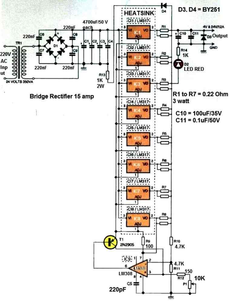
Circuit Diagram
The following figure shows the complete circuit of our high current switching regulator power supply using the IV L296.
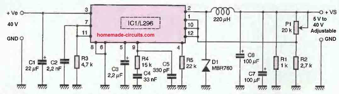
Why the Resistor R5 is Used
In our high current switching power supply circuit, the only important external passive component is resistor R5, which is only present if you use an L296P.
With this circuit, it limits the short-circuit current. The value indicated here sets this limit to around 4 A, while it is 7 A without the resistor, or with the L296 that does not have this capability.
We have not provided an output filter in the proposed L296 high current switching power supply circuit. Nevertheless, you can add one if you deem it necessary. It will then be identical to the one placed at the output of the LM2576 circuit.
We have not shown the classic transformer and its rectification and filtering circuit on these figures, which must precede either of these circuits as they have nothing special about them.
Power Supply
Regarding the power supply based on L296 or L296P, the limit will be 50V. Therefore, in both cases, be sure to size your transformer accordingly, keeping in mind that the open-circuit voltage across the filter capacitor following the rectifier bridge is equal to 1.4 times the available effective AC voltage at the transformer secondary.
Construction
For any respectable switch-mode power supply, the capacitors will be imperative low-ESR models, at least for those for which we have explicitly indicated in the component list.
Such capacitors are commonly available at FARNELL and RADIOSPARES, as well as for certain values at SELECTRONIC.
For this high current switching L296 adjustable power supply circuit, you will need to choose the P version of this circuit if you wish to be able to limit the short-circuit current to around 4 A using R5.
Otherwise, R5 will disappear, and the version without the P suffix is suitable.
The following figures present the printed circuit board drawings.
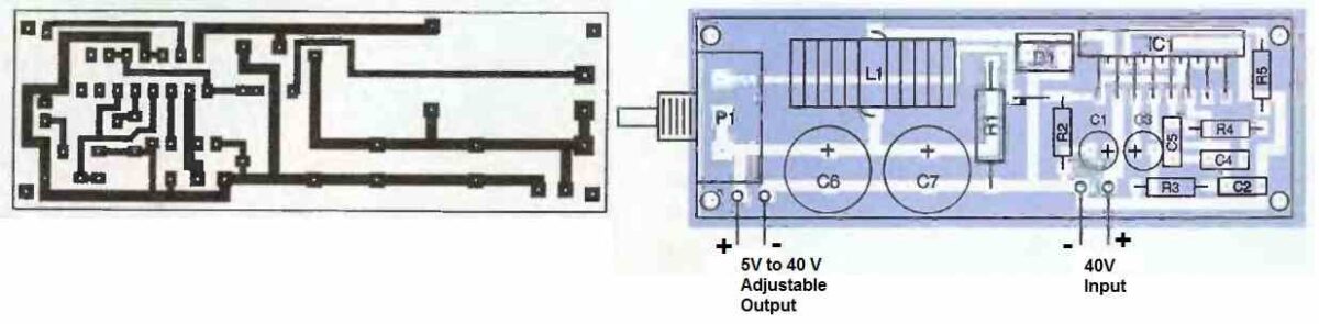
If we have planned to mount the voltage adjustment potentiometer directly at the end of the printed circuit board, it can be delegated to the front panel of the case receiving the assembly if necessary.
It can also be replaced by a fixed resistor if you do not want to make a laboratory power supply but only a power supply with a particular output voltage.
Although switch-mode power supplies have low thermal dissipation, the power of the proposed high current adjustable switching circuit still requires the use of a heatsink on the regulators.
However, it will be of a size that is much smaller than what would be needed for a linear power supply of the same power. In fact, the metal cabinet of the assembly can serve as a heatsink provided the metal is aluminum.
Note that in this regard the L296 has its metal tab connected to the electrical ground, making any insulation accessory unnecessary and facilitating the assembly and heat dissipation.
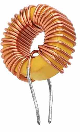
About the 220 uH Inductor
The inductor will need to be built over a large ferrite torroidal core, with a specific number of turns that corresponds to 220 uH. An example image of the inductor can be seen in the following figure.
How to Use
We won't be teaching you how to use an adjustable laboratory power supply, and this paragraph is only here to specify and remind you of the limiting characteristics of this high current adjustable switching regulator circuit.
As for the L296 or L296P version, the maximum input voltage is 50 V, and the output voltage is adjustable from 5 V to 40 V.
Regulation is ensured for an output current of less than or equal to 4 A. The short-circuit current is typically 7 A with an L296 and 4 A with an L296P and an R5 resistor of 22 kOhms.
Note that if you want to modify this value, the current increases as the resistance value increases and vice versa.
ST Microelectronics does not provide a calculation formula but offers a graph in the circuit's datasheet to determine this resistance based on the desired short-circuit current.
With all of these parameters in hand, you can now make good use of this high current switching power supply and appreciate the advantages of switching technology they offer.
Parts List
All resistors are 1/4 watt MFR 1%
4.7k = 1
15k = 1
22k = 1
1k = 1
2.7k = 1
20k potentiometer linear = 1
All Capacitors are 100V
2.2uF Electrolytic = 1
22uF Electrolytic = 1
100uF Electrolytic = 2
2.2 nF Metallized Polyester = 1
33 nF Metallized Polyester = 1
330 pF Ceramic Disc = 1
Semiconductors
IC L296 = 1
Fast recovery Diode MBR7600 = 1
Inductor 220 uH 6 amp = 1

Questions & Answers
Hi Swagatam,
Ref. L296 Power Supply.
I have replaced the voltage control pot.P1 20K with a 10 turn pot for more precise output control. However I have replaced it 2 times now with different makes of pots but both pots have blown. I think the voltage of 46VDC across the pot is to much for the pot.
However if I use a standard carbon pot then it works fine, but fine tuning is almost impossible.
So, I was thinking the answer might be to use two carbon pots, one for course and the other one for fine tuning.
What is your opinion. Can you please supply me with the modification details to achieve this.
Your advice will be much appreciated.
Regards
Jan
Hi Jan,
Even if it is a multi-turn pot, it should not burn because of the presence of the R2.
Anyway, your assumption regarding using two series pots for fine-tuning is perfectly correct, and you can definitely try it.
Hi Swagatam,
I have completed my L296 power supply. I must say that this was very much a worthwhile project. It works 100% even with a load that draws 1A. I have not tried a 4A load yet, but I am sure it will cope.
I want to thank you for your support. It is very much appreciated.
Lastly I would like to know if I want to use it as a battery charger, do I use the same cct. Or is there a different cct.
Kind Regards
Jan
That’s great Jan, Glad it is working for you!
Yes, definitely you can use this circuit for charging any battery effectively by adjusting the output voltage accordingly, however there’s no current control or over-charge cut off included in the above design, so you may have to include them in your battery charger design.
Hi Swagatam,
Thank you for your reply. However, I have noticed on your PCB layout that R1 is bigger than the rest of the resistors. It looks like a 2-5W 1K resistor?
Regards
Jan
Thank you Jan, for pointing it out!
Yes R1 can be a 1 watt or a 2 watt resistor, it doesn’t need to be a wire wound type, a normal CFR or MFR should work fine.
Hi Swagatam,
How important is it to use ESR capacitors in this cct.
Also can you please send me the component list.
Regards
Jan
Hi Jan,
According to me the capacitor quality spec is not critical and any standard type should work just fine, however for better reliability i would prefer metallized polyester type.
I have added the full parts list at the end of the post, you can check it out….
Hi Swagatam,
Is this a tested cct? If so it will save me the trouble of building it first on a breadboard. I Can then just build it directly on the PCB instead?
What is your opinion regarding this?
Regards
Jan
Hi Jan,
It is not tested by me, but the designs are referred from the Datasheet of the IC, so it cannot be wrong, it will definitely work, just make sure the IC is original make.
However, I would always recommend testing a circuit on a breadboard or a strip-board first, regardless of whether it is a tested design or not.
Please let me know if you encounter any issues with the circuit…
Hi Swagatam,
I am cant get the Schottky diode MBR760. However I can get a YG805C10R rated at 100v 20A. Can I use this instead?
Regards
Jan
Hi Jan,
According to me, that should work, you can use it.