In this article I have explained the formula and techniques of configuring RC circuit networks for controlling the arcing across relay contacts while switching heavy inductive loads.
Arc suppression
An arc is produced across the contacts when a switch or a relay is opened. With time, this condition can wear down the contacts.
To overcome this problem, an Resistor/Capacitor or RC circuit is deployed across the contacts and safeguard them. Once the contacts are open, the applied voltage goes through the capacitor and not the contacts.
During the process, the capacitor charges up faster than the contacts opening time which eventually avoids an arc from forming across the contacts.
Inrush Current Suppression
When the contacts close, the inrush current from the charged capacitor and the supply voltage can be significantly higher than the ratings for the contacts thus causing them to worsen.
To prevent this, a resistor is introduced in series with the capacitor. It functions as a current limiter by absorbing the inrush current significantly thereby reducing the produced arc and extending the life of the contacts.
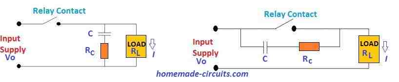
C.C Bates developed a formula for calculating the resistance and capacitance value that is required for the RC network: C = I2 /10, and Rc= Vo /[10I{1+(50/Vo)}]
The voltage induced at the contact opening can be determined by
V=IRc= (Rc/RL) Vo
- Where VO = Voltage source
- I = Load current at contact opening
- RC = Resistance of RC Snubber
- C = Capacitance of RC Snubber
- RL = Load Resistance
In our following examples we talk about the reed relay arcing issues, and try to evaluate the calculations required for designing RC networks across its contacts.
Since the principle of arcing may be the same in bigger relays also, the formulas used in reed relay could be also applied for dimensioning the RC networks for the bigger relays.
How Arcing Happens in Reed Relay Switching
A reed switch or reed sensor can be used for controlling an inductive device like a relay coil, solenoid, transformer, small motor etc.
When the reed switch opens, the charge stored in the inductance in the device will force the switch contacts to a high voltage. Once the switch opens, the contact gap is tiny in the beginning.
Therefore, arcing between the contact gap can happen almost immediately while the switch is just opening.
The phenomenon can occur in both resistive and inductive loads, but since the latter produce a higher voltage, increased arcing activity is seen thus reducing the switch life.
A diode is normally used by the DC inductive circuits to avoid high voltage. This type of diode is called the flyback, freewheeling, or catch diode.
Unfortunately, the application of this diode is not possible in AC circuits.
So, we must use a metal-oxide varistor (MOV), a bidirectional transient voltage suppressor (TVS) diode or an RC suppression network, also known as a snubber.
These diverse arc suppression approaches have many pros and cons. Not using suppression is also an option if the relay contact life isn't affected without it.
The many factors that determines which approach needs to be undertaken, include cost, contact life, packing etc.
The fundamental reason for spark suppression circuit designs is to minimize arcing and the noise generated when engaging relays and switches.
RC Design Considerations
Using DC supply with TVS Suppressor Diode:
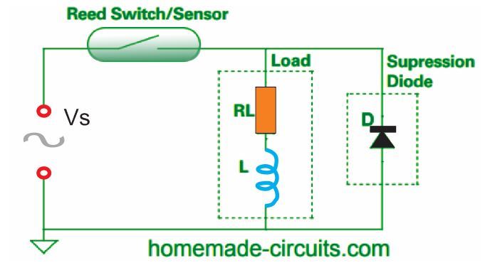
Using Bidirectional TVS Diode
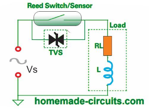
The MOV and TVS diodes conduct current when a threshold voltage is surpassed.
Normally, these diodes are connected parallel to the switch contact. Even at low voltages like 24 VAC, these devices are capable of working efficiently.
Moreover, they can also function well at higher inductance 120 VAC loads. Compared to TVS diodes, MOV devices have added capacitance.
Thus, when an MOV device is utilized, you must consider the capacitance to be used. The Hamlin application note describes this scenario better.
RC suppression had the edge because of limiting the switch contact voltage exactly during switch opening when the contact gap is small.
Furthermore, RC suppression can be implemented to lessen arcing and improve life in resistive loads.
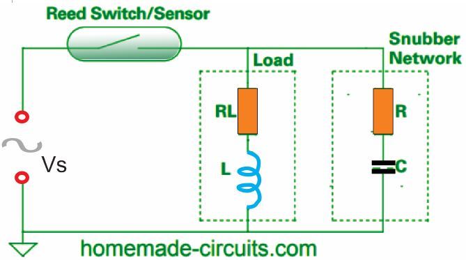
On an RC suppression circuit, a capacitor and resistor network connected in series is mounted across the switch contact in a parallel connection.
Another option is to place the capacitor and resistor across the load.
While attaching the RC snubber across the switch contact is ideal, there is a huge disadvantage because this creates a current path to the load when the switch is open.
If the snubber is installed across the load, it eliminates the current. However, changes in the connections and source impedance can affect the efficiency of the arc suppression.
Applying RC Snubber Parallel with the Switch Contact
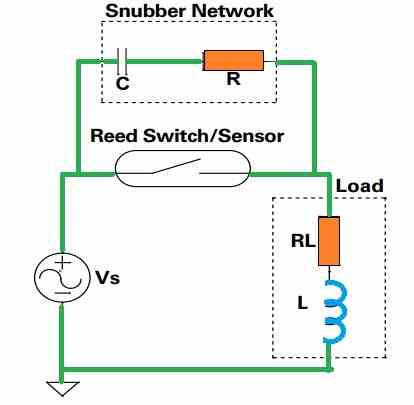
In the snubber, the values of the resistor and the capacitor are dependent on the requirement.
The chosen resistor must have a value high enough to restrict the capacitive discharge current when the contacts of the switch close. At the same time, it must be small enough to restrict the voltage when the switch contacts open.
If you choose a large capacitor value, it will surely decrease the voltage impact while the switch contacts opens.
But larger capacitor can be expensive and might cause higher capacitive discharge energy during the time the contacts of the switch close. This type applies to both DC and AC circuits.
Using RC (Snubber) Suppression Parallel with the Load
Ohm’s law is applied to choose the most appropriate resistor value for the arc suppression.
In the Ohm's law R = V/I, we apply the formula R = 0.5 (Vpk / ISW) and R = 0.3 (Vpk / ISW), where Vpk is the AC peak voltage (1.414 Vrms) and ISW is the rated switching current of the relay contact).
To decrease the contact degradation due to arcing, we have to make sure the R value is minimum. On the other hand, the R value must be increased to lessen the relay contact arcing due to the inrush current.
Determining the value of R in between these scenarios is the challenge.
You can begin with C = 0.1μF or 100 nF, when selecting the capacitor because this is standard value and thus cost-friendly. Depending on the performance examination of this capacitor, you can increase it until the capacitance is sufficient.
There are multiple methods to assess the performance of the chosen snubber values. Some can be performed just by calculation or simulation. However, the resistive and inductive features of the load may appear indefinite.
This is largely caused by the inductance of electromechanical loads that fluctuates when the components change positions.
It is a good practice to examine the voltage waveform across the switch contacts via an oscilloscope especially during contact opening. The snubber system should alleviate or at least minimize the arcing that happens when the contacts open and close.
The increasing voltage should not restart contact arcing. Furthermore, the maximum voltage across the capacitor in the snubber must not be more than it’s voltage rating.
Yet another way to find out if the snubber is working properly for a reed switch is to look at the switch contact gap and inspect the radiance of the light produced by the arc.
If there’s less light, that means the energy generating the arc is little and therefore warrants longer life.
The final and most precise method of examining the snubber’s performance is to conduct a life test.
Contact life is directly proportional to the number of switching cycles and not to the number of powered and unpowered hours.
It is advised to keep the maximum number of operations per second for life testing of arcing loads is around 5 to 50 operations per second.
This is around 5 to 50 Hz of maximum frequency. The number of tests you can carry out is reliant on the electrical load and the difference between convenience and precision.
When you need to find out the specifications of the components for the snubber, you must consider a few other things also apart from the described inspection of arc evaluation, highest capacitor voltage and life.
It is fundamental that when a switch contact is opened, current flows through the snubber circuit.
You must ensure that this current does not cause trouble to the snubber’s application. Moreover, it is essential to confirm that the power dissipation in the snubber’s resistor does not surpass its power rating.
One more thought is that an RC snubber circuit can be utilized in combination with a bidirectional TVS diode of MOV.
An RC snubber can be a highly efficient circuitry in limiting the initial voltage across the opening relay contacts, while the TVS or MOV may be a more efficient alternative for restricting peak surge voltages.


Questions & Answers
I have an DC relay application that I am attempting to calculate RC values for…or would a TVS diode/RC combo be more effective?
110 – 125 Vdc relay coil with 1/3 HP capability (3.6 – 3.2 Amps).
I am a transformer and LC filter design engineer for large variable speed motor drives, so this is a bit outside of my usual area of expertise.
Any thoughts? More info required?
Hi, I think the above article has all the required information and calculations that can satisfy your query.
Hi Swagatham
I have a reed like switch with contacts which I connected in series to actuate a 24 volt AC solenoid to open a water line for topping up water in a small tank this reed switch is actuated by a float arrangement, the contacts are arcing when breaking especially sometimes when making contact and causing chatter to the solenoid which is very noisy
What can I do to suppress this arcing, can I use a non polar capacitor of 0.1 uf/ 200 V or a 0.22uf/200V capacitor across the contacts ?kindly help and let me know you can also email any circuit in this regard
Thanks & all the best & God bless
Kind regards
Vee
Hi Val,
I think a solenoid is quite a big load for a reed switch to handle. You should use the reed switch to operate a relay first and then use the relay contacts to operate the solenoid.
If you use a reed switch to operate a solenoid directly, the high current switching will cause the reed switch contacts to spark, melt and fuse with each other.
I have a video posted in the following article which uses a reed switch to switch ON a 12V relay
https://www.homemade-circuits.com/float-switch-water-level-controller/
This is a good and complex topic and very useful for a lot of people, so thank you for addressing this in a short and concise way. I have a few questions though, and I would appreciate very much if you could answer to clarify some things contained in the article:
The formulas above (developed by CC Bates: C = I2 /10, and Rc= Vo /[10I{1+(50/Vo)}]), don’t show the unit of measure for the C (F, uF?). Usually the unit used in formulas are in Farads, but to be sure, is that the case here as well?
For example, the calculated RC snubber values for a 9A motor (1.5HP single phase 120V) with a 2.1 Ohms winding come out to be 0.941 for the resistor and 8.1 for the Capacitor, which if it was Farads, that would be huge. Also, the voltage induced at the contacts opening comes out to be about 53.8V here. I suppose that is to be added on top of the source voltage for the total surge?
Thank you so much!
Thank you and glad you found the post useful.
In any electronic formula, the units will be SI units. For example resistance will be in Ohms, current will be in Amps, Capacitance will be in Farads, Potential difference in Volts.
So the capacitor will be in Farads.
I have some questions about C.C.Bates formula about arcing across in this case PLC output contacts rated at 300mA
1- Is Rc the value of the resistance inside the RC network ?
2- Value of Rc using the formula is in ohms or k ohms ?
3- Is C the value of the capacitance inside the RC network ?
4- Value of C using the formula is in Micro, pico, nano or entire farad ?
5- should i use common unpolarized ceramic disc capacitor ?
6- What dielectric strenght voltage that capacitor should have for inductive load at 120Vac,with current
between 100- 300mA ?
1) Yes Rc is the value of the resistor in the RC network
2) It will be in Ohms
3) C is the capacitor inside the RC network
4) C will be in Farads
5) use non polar capacitor
6) Voltage value will depend on the voltage used across the relay contacts or the load wherever the RC is connected. 2 times this value
Hello,
I’m not an EE so I need your help. I had a magnetic reed Sw. that was operating a resistive light strip in my desk keyboard drawer. It operated fine for years. When the light strip failed I replaced it with an LED strip.
The reed switch immediately welded closed. I purchased a small repay to operate the LED but now realize the coil of the relay may affect the reed switch in the same way as the LED PS. It is a 120 V circuit and the coil measures 2.5 K ohms. That’s all the circuit information I can give. Can you give me a MOV or R – C snubber spec that I can order?
Thanks
You can put any capacitor between 0.22uF/400V and 1uF/400V across the reed contacts, and see if that helps!
Ok, just a cap across the reed switch. no R-C network or MOV needed, got it.
Thanks for you quick response, I appreciate it.
yes, according to me a single capacitor across the reed contacts should do the job!
A zener snubber would not work by itself for an AC load. But if the zener were in the DC arms of a full-wave diode rectifier with the AC arms parallel to the load, the zener would see the spike as DC. The zener and full-wave rectifier approach appeals to me as the inductance of the load in my intended application will change. I would be interested if others use this approach – I do not see it published, at least on the internet.
Hello,
I am interested in using a snubber circuit as an Arc Suppression circuit for PoE applications. PoE voltage is 57vdc at 1 amp. When a network cable is inserted into the mating connector, the PSE senses the connection and sends PoE power after the contacts mate. No chance to arc during mating the connectors. Upon disconnecting the network cable, the PoE power is making an arc causing contact damage in the connectors. I want to add a switch to one of the connector lines that has a snubber circuit to reduce or eliminate this arcing. This line, being disconnected by the switch, before the connector contacts un-mate, will signal the PSE to shut off power to all lines. Would the snubber circuit be able to be simplified since I only see arcing during unmating?
Hello, thanks for the detailed explanation. According to me a single capacitor rated at may be 0.47uF/100V connected across the switch contacts should be enough to absorb the arcing and prevent it from happening. Let me know if this works for you!
Hi i was wondering if you could help i am trying to figure out the best way to put a arc duppresion circiut on a bidirectional dc motor that is drastically shortening the contact life of the switches down to a few cycles what would be the best way to go about this motor voltage is around 14v….thank you
I guess you can try putting a 1uF/100V non polar PPC capacitor right across the contacts, and check if that helps! You can also put the same capacitor across the motor terminals.
I know I’m late to the party .. but the only arc suppression device you need on a DC motor is a large resistor (1K – 3300 ohms). The coil on a stepper motor is like an inductor when the motor stops. The character of an inductor is that its current flow cannot instantly change. to make that so .. the voltage on the coil can and does assume a voltage as “high as it needs to be” (a few hundred volts is not unusual) in order to sustain the flow until the field collapses. That’s where the spark comes from … the voltage jumps high enough to ionize air (to gain conductivity). give the current an easier path with a resistor, and the max voltage will be MUCH lower, and the spark will cease.
When you say, in the opening paragragh, “During the process, the capacitor charges up faster than the contacts opening time which eventually avoids an arc from forming across the contacts”
I think what you meant is, “During the process, the capacitor charges up faster than the contacts opening time which PREVENTS an arc from eventually forming across the contacts”
I think I know what you meant, but by the way it is written, it sounds as though the capacitor doesn’t actually work at first, and only starts preventing the arc “eventually”.
Thanks for improving the structure of the sentence, I hope the readers will find it useful.
Hi,
Thanks for your all useful articles. I always learn a lot from these. I’ve some confusions in my mind regarding this article and also probably some diagrams are wrong labeled. Please take a look and clear me where I’m wrong (as I guess, I’m :-)).
1. Where is the best place to put RC snubber in AC circuits. Across the load or across the relay contact switch?
2. Diagram under “Using DC supply with TVS Suppressor Diode” heading, power supply source is shown AC instead of DC.
3. Two formula, “R = 0.5 (Vpk / ISW) and R = 0.3 (Vpk / ISW)”. What is difference between both? I mean one is using 0.3 and the other is using 0.5 in it.
4. What is the voltage of AC source used in these diagrams. (or it is not necessary to show?)
5. In diagram under “Using DC supply with TVS Suppressor Diode” heading, diode is connected to parallel of load while context says, “Normally, these diodes are parallelly connected to the switch contact”. So where is the right place to connect at ? parallel to switch or parallel to load?
6. The diagram under “Applying RC Snubber Parallel with the Switch Contact” heading, have a TVS diode instead of RC.
Regards.
Hi, thanks for the useful questions. First of all I would like to say that I am not an expert in this subject, all the data were contributed by another author by referring from external sources (links given at the bottom of the article)
1) I think the best place to connect an RC snubber is across the load.
2) Yes, all the diagrams are wrongly shown with an AC input signal, they all should be DC symbols. Even the original article wrongly shows the AC symbol in their diagrams:
https://m.littelfuse.com/~/media/electronics/application_notes/reed_switches/littelfuse_magnetic_sensors_and_reed_switches_inductive_load_arc_suppression_application_note.pdf.pdf
3) I am not sure about the formulas, I have not yet investigated them deeply.
4) The AC or DC inputs can be of any value. And depending on the input voltage specs the relay contact rating and the snubber rating must be dimensioned accordingly.
5) For TVS diodes it must be parallel to the contacts according to me, but it can be also connected across the load which will be less effective than connecting across the contacts.
6) That’s right, I will check the article and do the necessary corrections soon, if the original allows me to do this.
I’m trying to use an electric charcoal starter (house current, 120VAC) that trips the circuit breaker every time I use it. I’m thinking (hoping) that the crazy-fast inrush current when I plug in the starter is what trips the breaker. And I’m thinking (again hoping) that a simple RC network would slow down the current ramp-up so that it would not trip the breaker. This is for my patio grill.
Am I on the right track? If so, is there a device I could buy or build to do this?
Thanks.
I don’t think an RC snubber would be able to restrict such high current inrush. I would rather suggest using a triac based light dimmer circuit in series with the starter. Initially keep the light dimmer control at 50%, and switch ON the starter and then slowly increase the light dimmer control to 100%.
220V Light Dimmer and Ceiling fan Regulator Circuit
Hey Swagatam. I just stumbled across your site today while looking for something.
At some point you made the schematic for an underground wire locater, and that’s just what I need. THe wire is open on one end and not powered in any way , but I can’t find the other end. Its likely about 100 feet long (this is 30 volt lighting cable) and I need to trace it along the ground its about 6 inches underground. Can you tell me where to find the non-fuzzy schematic / instructions for that?
I am also a BSEE (a 2 way radio engineer) , but have been chasing money a different way for a few years. I love projects still, and will build some of yours.
Thanks Dan for visiting this site!
I tried to find the mentioned circuit in this blog, but unfortunately I don’t think it is still available or maybe it was deleted long back. The only related circuit which I could find is the following one:
https://www.homemade-circuits.com/stud-finder-circuit-find-hidden-metals-inside-walls/
Hi Swagatam,
I am using 24 VAC relay for controlling heate in one of my machine and we are giving 230VAC (Current = 18 A) to heater through the relay. As per your post there is spark while opening of contact and it will create carbon on relay contacts and it will stop working after some time.
Could you please suggest the value of R and C to be used in RC snubber circuit.
Thanks in advance.
Hi Mitul,
I have provided the formula in the article which you can use to easily calculate the values. Alternatively you can try the values randomly for example use a 100 ohm resistor and a 0.1uF/200 V capacitor. Keep experimenting until the spark becomes minimal
Means I have to increase the value of resistance and capacitor if 100 ohm and 0.1uf/200v is not able to reduce the spark, right?
You must try reducing the resistor value or increasing the capacitor value, or try both.
I have a peculiar problem with a PCB. This has an esp12f attached to two relays. The PCB has ground and working fine except when I connect a ceiling fan through a speed regulator. When I do that, I get abrupt restarts of esp12f. I have an RC snubber with CB221 capacitor and 390ohm resitance across the load which has improved the stability of the system. Now the restarts are heavily reduced but still there. How should I try changing the snubber to completetly eliminate this?
You can try increasing the value of the snubber capacitor to 1 uF. Additionally you can also add decoupling components right across supply pins of the ESP12F. You can add a 12V zener diode, a a 1N4148 diode, a 100uF capacitor, and a 0.1uF capacitor
I already have a 1000uf capacitor across power pins of esp12f. I was using 0.4uf capcitance. Since I didnt have 1uf, i will try with 0.68uf now.
Also where should I add zener diode and the rest? I am using a 5v power supply which supplies to relays directly and a part is stepped down using ASM117 module for esp12f
The zener diode and the 1N4148 diode will need to be connected right across the supply pins of the ESP IC. Cathodes will go to the positive supply pin and the anodes will go to the negative or the ground supply pin of the IC. If possible connect two 0.68uF in parallel across the relay coils. Additionally you AC dimmer circuit might also need RF suppressors in the form of an RF choke and a 0.1uF/400V capacitor.
Ok will try all these and update.
I couldn’t implement the changes with these changes but I found one more thing which may help us. If I use different AC lines/phases to power the esp12f 5v power supply and the ceiling fan power supply, then there is no such problems. But I cann’t do that as I need th esp12f and fan to work with my inverter backed up line. any ideas why this happens.
also snubber with 0.68uf across load is same as 0.4uf. now i will try 1.5uf
It mostly happens due to RF voltage spikes that can upset or rattle a sensitive electronic circuitry or an IC. This is mostly solved by adding capacitors and zener diodes across the supply pins of the IC, or by adding an adequate snubber across the RF source.
AC triac based dimmer circuits emit a lot of RF interference, that could be also one of the reasons.
I am using Legrand Myrius Fan step regulator 100 which should not be triac based. I already have 1000uf capacitor across power pins. now i will add 3.3v zener diode. Also increase snubber capacitance to 1.5uf. And lets see what happens. I am using 330ohm as resistor for snubber, should i change it?
OK, in that case it could be the switch ON back EMF spike caused by the fan’s internal winding. Adding a zener diode and also a 1N4148 diode are very important. Add these across the supply terminals of the IC. Make sure to add a 100 ohm resistor also in series with the positive supply of the IC this will prevent loading of the zener diode and also help to restrict the Rf spike into the IC.
If you have a reset pin or some other sensitive input pin for the IC try adding decoupling to these pins also.
Hi there, sorry for late update but i had to order the parts which only got here yesterday. Is the 100 ohm resistor mandatory. i am asking bcos i may have to cut the a pcb trace to add it in series with positive supply. My RS pin is already connected to 3.3v through 10k resistor. should i add decoupling capacitors to this?
Also should I connect one of the snubber terminal to the output of the speed regulator or input? Right now I hav connected it to input and the other terminal I have connected to neutral.
Yes, you should add the 100 ohm resistor which will ensure better RF regulation. You can also connect a 0.1uF capacitor between the RS pin and ground.
I cannot understand the input/output snubber connections that you are referring to, I will have to see the schematic to understand it.
You said your speed regulator was DC, right? But since you are using the word Neutral, I am confused, is the regulator and the FAN AC operated?
No my ceiling fan as well as speed regulator is AC.
I have been adviced to connect the snubber across the load which is the fan and so I have connected one terminal of the snubber to the speed regulator terminal where the AC supply is given. To connect the snubber parallel to the load, I have connected the second terminal to neutral line which is also where th fans return line ends. I hope i am able to explain this.
You can connect the snubber across the load, meaning right across the load terminals. However protecting the IC using decoupling circuit is also very important to safeguard it from the RF spikes. Since your dimmer is an AC dimmer, make sure it has an RF suppressor using an LC network internally. If LC network is not present then your dimmer will create a huge amount RF noise which can disturb any electronic circuit.
You must use a zener diode, 1N4148 diode, a capacitor all in parallel right across the supply terminals of the IC, and also feed the positive supply to the IC through a 100 ohm resistor.
See if these measures help, otherwise it can be a difficult situation to handle.
Actually I had been doing some tests without adding the zener, 1n4148. I was able to reduce this issue to just 0.5% of total operations with just the snubber of your design which i was connecting across the inputs of 5v power supply. Today i tried to increase the capacitance of decoupling capacitor of esp8266 but after that the problem came back. I replaced with old capacitor but still problem persists. I also noticed that the resistor(390ohm) of the snubber is getting very hot which was not like before. what could be happening? is the snubber gone bad?
The decoupling capacitors must be two parallel capacitors, one around 100uF and another around 0.1uF. Where and how did you connect the 390 ohm, I will have to see the schematic to understand the issue. According to me the zener diode must be included and also a 50 or 100 ohm resistor in series with the positive supply of the IC.
by decoupling capacitor, I meant the 1000uf capacitor which is cannected across 3.3v and gnd of esp12f. It is different from snubber.
The snubber circuit I have been using is of RC type with a varistor added. The capacitor is CBB684J400V and resistor is 390 ohm. I have connected this across the input of the 5v power supply that powers the esp8266 through an asm117 module.
see circuit
I don’t think an RC snubber across a 220V MOV is going to help you to eliminate switch ON spikes. The 1000uF is fine but make sure to connect a 0.1uF capacitor also along with a zener diode. You can connect another 1000uF at the input side of the 3.3 V regulator.
The zener helps to short circuit and neutralize the reverse RF spikes across any IC or circuit.
I will add the zener and In4148 tomorrow. Should i remove MOV from the snubber?
should i increase the capcitance of snubber?
I followed this schematics
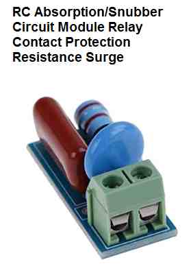
This snubber is supposed to be connected across a relay contact, not across the 220V AC input.
do you mean snubber is to connected across relay coils which is 5v dc? But in the blog, it is connected across AC
Snubber is normally connected across relay contacts, triac, or an AC load.
Your relay coil may be 5 V DC but what voltage is it switching across its contacts?
The previous snubber module image which you showed me is intended for relay contacts terminals, not for AC mains input terminals
My relay is switching a ceiling fan connected through a speed regulator working on 220v AC supply
OK, then the snubber should be connected across the active contacts of the relay.
I have connected the snuber between the hot contacts of the relay but the prolblem is that the fan is not stopping. It just continues to spin very slowly even when relay is off.
OK, but did you check whether it is solving the actual problem or not? Is your IC getting reset now?
The initial trials seems to indicate that the problem was solved but i was afraid to test it long term as the resistor was getting hot to touch and fan was spinning.
You can reduce the resistor value to maybe 47 ohms, and also reduce the capacitor value to maybe 0.22uF/400V, and check the response again. Basically you will need to experiment with the values of the resistor and the capacitor until both the issues are solved.
Oh ok. should I only try decreasing the resistance and capacitance or do i also try increading them. Is it normal for the resistor to heated up to touch.
Heating up of the resistor is not good. Decreasing the snubber capacitor and the resistor values will cause lower heat dissipation on the resistor. Decreasing the capacitor value will also prevent the fan from spinning slowly when switched OFF. However decreasing the capacitor value will also decrease the snubber power to cancel out the RF spikes. So you will have to experiment to find an intermediate value which will satisfy both the conditions.
Oh ok. I appreciate the help. I would keep you posted on this.
OK, no problem.
Hi there, as you advised i have been experimenting with capacitors and resistors. I found that 0.22uf and 100 ohm resistors are best match in my tests till now. Testing is still continuing. I was wondering how much approximate energy would this snubber circuit consume.
No problem, you can keep testing until you find perfect combination. The 0.22uF capacitor will allow around 10 mA current, so 10 mA would be constantly passing through the 100 ohm resistor.
After doing a good amount of tests I fixed the capacitor as 224J250V and resistance as 100ohms connected across the hot contacts of my relay. I really really appreciate you taking time for helping me. I am sure without your help, I couldn’t have solved this. Thanks again. Keep up the good work.
Also a final question should the snubber be very close to the relay contacts or can it be connected through a wire of 30- 50cm?
It’s my pleasure, Glad the problem seems to be solved now.
Increasing the distance will add resistance to the existing 100 ohms resistor, so the total series resistance of the snubber might become 105 ohms or 110 ohms depending on the snubber distance from the relay contacts, and the wire resistance.
Hi there. I came up on some more question.
Can I use the same snubber across two relays?
In the case I will explained above, it was one snubber for one relay which i connected to its hot contacts. If there is one more relay, Can I connect the same snubber to it’s hot contacts also(Assume both relay are switch the same AC phase). If yes should I make any change to the 224J250v capacitor or 100 ohm resistor.
Also if in a 3 phase system and both the relays are switching two different phase, what will be the situation with snubber?
If the hot contacts of the relays are connected in parallel to switch the same phase and the load then a single common snubber can be used. However, the snubber capacitor value might require some modification.
For 3 phase you will need 3 separate snubbers across the relevant relay contacts.
What about same phase and different loads, do we need seperate snubber for each relay?
Each separate relay will require a separate individual snubber regardless of the phase and the load, unless the hot contscats of the relays are connected in parallel. If the hot contacts are working separately then separate snubbers will be required.
Good day to Swagatam and Shemin, Nice to follow this communication thread. I learned a lot. I just have a clarification question on this. What if there are 4 relays and the one hot contact of the 4 relays are in parallel or connected and the other hot contact of the 4 relays are connected to each different loads (fan, heater, transformer, fullbridge rectifier) which are all connected to the same mains supply. Should we have 4 different snubber modules or we can use just one? I hope I was clear to illustrate this. Thanks again! 🙂
Good Day Kitt,
According to me, you will need 4 separate snubbers for all the 4 relays for better protection of each of the relay contacts.
Thanks very much Swagatam! wil do that. More power to u!:)
It’s my pleasure Kit!
Hello, I have a clock circuit with a small 5W motor that switches on each minute and runs for 4 seconds before switching off. There is what appears to be a 0.47 uF capacitor in parallel with the motor. Reading your article,I think this should be a RC Snubber Network to prevent arcing at the switch. How can I tell the difference between a capacitor and a Snubber?
Hi, the capacitor that you see parallel to the motor is mostly included to reduce noise interference generated by the motor.
If you want to protect the ON/OFF switch from arcing then you might have to put a snubber network parallel to the switch contacts.
In most cases a simple 1uF non polar capacitor across the switch contacts should be enough to prevent the arcing across the contacts.
You can try this and let me know. However, before this, make sure the switch contacts are rated appropriately to handle the motor load.
Hi Swagatam, thanks for your reply. I tried to post a reply earlier today, but it disappeared from the board. Apologies, I forgot to mention that this is an AC synchronous motor operating at 240v 50Hz. The component that is connected across the load looks like a capacitor, but it could be a RC snubber. How can I tell the difference? It is marked [BC 470n K 400]. Also, in your article you state that placing a snubber across the switch contacts has the disadvantage of creating a current path to the load. With a mains voltage circuit I am concerned about the safety issues of doing that.
There does seem to be a problem with arcing at the switch contacts, which are burnt and pitted. The switch is rated at 5A. It is a two way switch, where the load is common. The clock works with two Live mains connections to a master clock and a common Neutral. They are energised alternately each minute. So the motor runs until a cam changes over the switch contacts and it then waits for the next minute when the other live is energised. So if the snubber were to go across the switch contacts, I presume that two snubbers would be needed?
I hope this makes sense. I could send photos it helps, but cannot on this forum. Please e-mail me directly.
Thanks Andrew, actually I received both your comments. No problem here’s the answer.
The BC 470n K 400 definitely looks like a capacitor, most probably it is a 470nF 400V PPC capacitor. 470nF = 0.47uF.
Yes a capacitor across the switch will pass some current to the load, although this can be insignificantly small.
For example, you can try connecting a 0.33uF/400V capacitor across the switch contacts which may pass no more than 15 to 20mA current to you AC motor.
That’s right, you will require two of these capacitors connected across the two alternate connections of the switch.
Please try a 0.33uF/400V and check the results.
In fact you can go even lower and try a 0.1uF/400V capacitor initially and check whether that solves the issue or not.
0.1uF/400V will allow hardly 5 mA current to the load while the switch is turned off.
Thanks Swagatam, this is most helpful. I will try 0.1uF capacitors across the switch contacts to err on the side of caution regarding current to the load in the off state. It would be a big problem for the clock if the small motor (which only draws 20mA) continued to run when the contacts opened. Should these capacitors be in addition to, or in place of, the existing 0.1uF capacitor across the motor? I should add that this is a reversible synchronous motor chosen for it’s high torque. The direction of rotation is determined by a permanently connected 0.1uF dephasing capacitor between switched Live and one of the windings. So another capacitor in the circuit!
One other thing about capacitors across the switch contacts, in the article you say that a RC snubber includes a resistor to limit the capacitor discharge inrush current when the switch contacts close. I must be missing something here. Is there a reason for recommending just straight capacitors for my case?
Kind regards,
Andrew
No problem Andrew,
I understood the situation. In that case to be even more careful you can try using two 0.1uF/400V capacitors in series across the switch contacts, which would allow just 2.5 ma current to the load while switched OFF. Let’s see if that’s enough to neutralize the arcing across the switch contacts.
The existing capacitor across the motor should remain as is, since those are connected to control the noise interference from the motor.
A resistor in series with the capacitor is recommended, however that also reduces the snubbing efficiency of the capacitor according to my practical experience.
A direct capacitor would be more efficient to quickly neutralize the voltage arc generated during the switch OFF operations of the switch. To limit the inrush back discharge from this direct capacitor, it can be a very low capacitor initially, such as a 0.047uF, 0.022uF etc.
I would suggest you to try 3 combinations and check which one gives the best results.
1) two 0.1uF/400V capacitors in series.
2) a single 0.1uF/400V in series with any low value resistor such as 50 ohm or 100 ohm 1/4 watt.
3) A direct 0.1uF/400V capacitor connected across the relevant switch contacts.
Let me know how it goes and if you have any further questions.
Thanks Swagatam, that’s great. I’ll order some capacitors and RC snubbers as you suggest to do the experiments and let you know the results. As a matter of interest I have been looking at an equivalent clock movement by another manufacturer. The way it works is identical and there are a few differences in the construction. The synchronous motor has different rpm with 0.12uF dephasing cap, the microswitch is a different brand rated at 10A, and it has an RC snubber across the motor instead of a straight capacitor. The snubber is 0.1uF + 100 ohms. There are no additional capacitors across the switch contacts. I don’t know if there is any difference in contact arcing between the two movements. However, the switches do last a lot longer, making these movements more reliable.
Thanks Andrew! sure, please test the results and let us know how it works.
Connecting the snubber directly across the switch contacts is more efficient since the snubber is able to tackle the issue immediately across the switch contacts. On the other hand a direct capacitor across the motor terminals ensures reduced noise interference and smoother motor operations.
Since you would be having the snubber components with you, you can test both the options: snubber across the motor, and/or snubber across the switch.
I am hopeful the issue will be solved anyway.
Hello Swafagam,
Further to our discussion in Dec 2023 regarding contact arcing in a clock circuit. Following your suggestions I have done some experiments and testing in the workshop and thought you may be interested in the results.
Firstly, I realise that the circuit is more complex because the Live 1/Live2 mains signals from the master clock are supplied via two relays which have their own arc suppression capacitors on the master clock pcb. The master clock is some distance from the clock movements, but I guess those capacitors do have some influence on the overall circuit characteristics. Also, on site there are two clock movements in the circuit wired in parallel with the Live1/Live2 switching. They switch on and off simultaneously. Each time the switching changes from one live to the other, there remains some residual voltage in the line that has just switched off. I presume that this is the collective charge in the various capacitors? With no clock movements connected to the master clock, this residual voltage is approx. 81v. With the standard movement (0.47uF capacitor across the motor, no snubbers) connected to the master clock the residual voltage is 54v. I tried a 0.1uF + 120 ohm snubber across the switch contacts on one of the movements (so two separate snubbers for the two-way switch). I left the 0.47uF capacitor in place across the motor. The clock worked, but there was a buzzing from the motors of both movements while the switch was off. So there was current passing through the motors, albeit not enough for the motor to run. I measured this as approx. 1.3mA. With the switch on and the motor running, the current was 7.7mA. The residual voltage in the off state was 31v.
Next I tried two snubbers in series across the switch contacts and 0.47uF capacitor across the motor. The second clock movement was disconnected from the circuit. There was a light humming from the motor, which passed 0.65mA in the off position. Running current was 7.8mA, residual voltage in the off state was 17v.
I then tried the snubber across the motor in place of the 0.47uF capacitor. Motor current was 7.9mA running and 0mA off. Residual voltage in the off state was 66v. With the second movement also in the circuit (which also had a snubber across the switch contacts), the residual voltage was 90v.
I am not sure what is going on here. It appears that all the various capacitors & snubbers are working together to affect the outcome. I understand what you say about capacitors across the switch being more effective. However, I am not happy about this. There is a small current constantly passing through the motor causing buzzing / humming even when in the off state and could lead to overheating. It occurs to me that if I reduce the capacitance value to the point where no A.C. current will pass, there will not be sufficient spark energy absorption.
The second movement used for this test is a different brand, but works in the same way. As standard, It has a snubber across the motor which is 0.1uF + 100 ohms. No capacitors across the switch. I didn’t measure the motor current for this movement, but with just this movement connected to the master clock the residual voltage in the off state was 38v.
The switches are enclosed microswitches, so I cannot see how these experiments have affected the contact arcing. Only time will tell if the contact pitting has been reduced. Is there a way to measure spark energy?
Kind regards,
Andrew
Thank you Andrew, for the detailed analysis,
From your explanation it seems your motor is very sensitive, since it is able to sense even a current that’s as low as 1 ma.
However, the question is, how come this 1 mA current is not getting bypassed by the 0.47uF capacitor across the motor?
Would it be worth increasing the 0.47uF to 1uF, so that the 1mA current from the switch snubber capacitor is bypassed through it?
I am not very sure how the spark intensity can be captured and measured through a simple arrangement… Although I guess, it can be perhaps done via some sort of RF sensor circuit, and measured by connecting a voltmeter at the output of the RF detector.
I have one such design explained in the following post, you can try this circuit and check the response by keeping the antenna close to the relay contacts.
https://www.homemade-circuits.com/bug-detector-circuit-rf-sniffer-circuit/
Hi Swagatam,
Thanks for your reply. It’s a good point about the 0.47uF capacitor across the motor. I think this is down to the way I measured the current and I may have to repeat the experiment. 1.3mA was measured just through the motor. There may actually be a higher current passing through the snubber across the switch, and split between the motor and capacitor. I will measure again at the motor/capacitor connector.
I won’t have time to build the RF sensor circuit, but it just got me thinking that I can perhaps listen to the click on an FM radio placed nearby.
Comparing the two designs of clock movement I have, it is the one with 0.47uF capacitor across the motor that is troublesome. But since the other movement has a lower value capacitor 0.1uF in the snubber, I would have expected this one to have worse arcing. Is it the 100 ohm resistor in the snubber that is the key?
Kind regards,
Andrew
Thanks Andrew, We will wait for new updates from you.
Listening to a radio for confirming the relay arcing is a good idea, however the radio must be an AM radio, an FM radio won’t be able to pick them up.
The resistor actually helps the to create a smoother damping of the high current discharge through the capacitor, it also limits the current through the capacitor, extending the capacitor life.
This resistor may also reduce the leakage current through the motor while it is switched OFF, and thus might help to reduce the buzzing sound in the motor.
Hi Swagatam,
Thinking of trying a lower value capacitor or RC snubber network across the switch contacts. O.1uF+120R passed enough current to cause buzzing from the motor. Two snubbers in series less so. That is a potential reliability issue as the motor is only prevented from starting by some of that current being diverted through the RF suppressor capacitor.
I understand that capacitors in series follow the reciprocal rule, so 3 x 0.1uF = 0.033uF. Does this also apply with snubbers in series? Ie. Would 2 x (0.1uF+120R) = 0.05uF+240R ?
My reason for asking is that I tried to get some lower value snubbers, but found nothing with the required voltage rating, so would have to use the 0.1uF 600v ones I have, perhaps 3 or 4 of them in series.
Kind regards,
Andrew
Hi Swagatam,
I did some more testing today and yes, I had measured the motor current in the wrong place. The currents I gave earlier were just through the main motor winding. They did not take into account the dephasing capacitor and start coil or the RF suppression capacitor in parallel with the motor.
So the total switched load current with 0.47uF capacitor across the motor is 39.8mA. With 0.1uF + 120 ohm snubbers across the switch contacts there is also 6mA passing when the switch is off. This causes the motor to buzz but not run.
The total switched load current with the 0.47uF capacitor removed is 13.3mA. Also the same with 0.1uF + 120ohm snubber across the motor. With snubbers across the switch contacts, there is also 6.3mA passing when the switch is off. This causes the motor to run continuously.
So I think I may have found the root of the problem. The 0.47uF capacitor is allowing excessive current to pass, with consequent arcing at the switch contacts. Replacing it with a 0.1uF+120 ohm snubber will reduce the current. Will this also reduce contact arcing? I am hoping this will do instead of snubbers across the switch contacts, which seems to be problematic for the motor.
Kind regards,
Andrew
Thanks Andrew,
That makes sense, the 0.47uF across the motor could be causing an increased arcing through the relay contacts.
The 0.1uF + 120 ohm across the motor might help to reduce the relay contact arcing significantly, because now there won’t be any additional current draw except the motor current.
However, if it doesn’t then perhaps the only remedy would be to increase the relay contact rating, so that the arcing doesn’t degrade the contacts overtime.
Another option could be to introduce a slow-start or a soft-start for the motor, but that would require an external 555 based circuit.
…the soft-start for the motor appears to be a good idea according to me, and it can be simply implemented using a transistor, resistor and a capacitor.
Thanks Swagatam. Soft start sounds interesting. Does this cause a delay in the motor starting? Timing is critical for this clock system to work correctly. The motor and switch normally complete their cycle in 4 seconds. The master clock supplies current each minute for 6 seconds only.
It is a 50Hz synchronous motor with a 0.1uF dephasing capacitor to start it in the correct direction. Can this type have a soft start?
Kind regards,
Andrew
Hi Andrew,
I completely forgot that it is an AC motor, so transistorized soft-start cannot be used. There is another method using triac for AC motors, but it is a bit lengthy circuit.
Moreover if timing is crucial then soft-start can be problematic since it will cause the motor to start with a reduced speed initially, and reach the normal speed within maybe a seconds period.
But if implemented it can completely eliminate the relay arcing problem.
what is the RPM of your motor? I guess synchronous motor already have RC circuit provided by company.
Hi Sanjay, It is a reversible synchronous motor, 250rpm, with a 0.1uF dephasing capacitor to one of the windings to determine the direction of rotation. As far as I know there is no RC circuit built into the motor. There is a 0.47 uF suppressor capacitor across the motor.
I have a temperature controller board based on atmega32A and PT100.
I am using SINGLE good quality relay on BOARD. ( Hongfa 5V 5A DC HF49FD/005-1H11TF 4 Pin SPST Miniature Power Relay)
I am worried about life of RELAY.
I am using this board for multipurpose, I mean Board is used for various purposes.
In One case, I am controlling a 300W heater with this relay. (heater is a resistive load?)In second case , This board is used to control compressor indirectly.
Please Note: Between RELAY and Compressors, I am using an 220V AC
SSR.
I mean REALY is connected to 220V AC SSR and compressor is connected
to SSR.
I was thinking to use RC circuit for RELAY contact.
Capacitor value I am thinking to use is MKP-X2 0.1uF K 275V , what should be value of Resistor for this relay. Please suggest ………..
Please Note: I am switching SSR, which is rated 220AC 40A with my RELAY.
Important Point: DO readymade RC circuit package like are better?
The heater is the actual load which may cause the arcing. The compressor is through an SSR, so it is not a matter of concern.
You can experiment with any resistor between 22 ohms and 100 ohms, and select the one which generates minimum sparking across the contacts.
The ready made ones are also good and can be tried, but you cannot customize them for maximum efficiency.
The compressor is through SSR and SSR is connected to relay?
can it possible to use TVS diode in place of RC circuit?
The SSR input side works with a very low current trigger, which will not cause any load on the relay contacts.
Yes, TVs diodes can be used, but RC is easier to customize and estimate.
readymade RC module available on amazon and other sites has 0.1uf capacitor and 220 ohm resistor. Is 220 ohm is at higher side?
when the relay contacts are closed , does value of bigger resistor can product harmful current/voltage ?
We can judge the resistor value or the capacitor value only by testing the results practically, because the arcing depends on the amount of current and voltage passing through the relay contact.
The resistor value will not cause harmful current or voltage, it will only affect the snubber efficiency.
To ensure longer life the relay contacts must be rated 2 times more than the maximum current it is handling.
float C, Rc, V;
C = (I * I) / 10;
Rc = Vo / (10 * I * (1 + (50 / Vo)));
V = (Rc / RL) * Vo;
float Vo = 250.0; // source voltage in volts
float I = 3.5; // load current at contact opening in amperes
float RL = 500.0; // load resistance in ohms
the result is :
Capacitance in microfarads: 1225000.000000
Capacitance in nanofarads: 1225000064.000000
Resistance in ohms: 5.952381
Induced voltage at the contact opening: 2.976191
i try to use your formula please check error and replay