The post narrates a simple water level controller circuit using a float switch mechanism. The idea was requested by Mr. tpraveenraj.
Technical Specifications
I'm a electronic hobbyist from software field. So I try with the things in the weekend. I saw your blog recently and really admired to test this circuit, and when I went to the market I saw the float switch there.
Can I connect that to this circuit, or else will you please suggest me the way to use that, since we don't have to worry about the corrosion & passing currents to water by using this switch.
Thanks for your great works, they are really helpful for the people like us to learn.
The Design
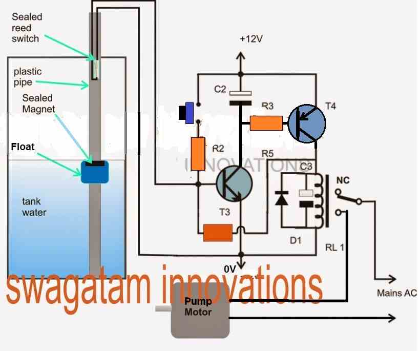
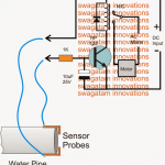
The proposed water level controller circuit using a float switch is basically a semi-automatic system where the pump is started manually by press of a button, once the water level reaches the brim of the tank, the operation is switched of automatically by means of a float switch.
Referring to the diagram shown below, the various stages and functions may be understood with the help of the following points:
The left side of the image a shows the tank half filled with water along with the associated float and switch mechanism.
The Float Sensor Mechanism
The float mechanism basically consists of a smooth cylindrical water sealed plastic pipe, clamped erect inside the water tank inner base.
A plastic water-tight float surrounds this pipe and is able to slide up/down freely in response to the water level inside the tank.
The float being made up of plastic floats at the water surface and is consequently pushed upwards or downwards across the plastic pipe depending upon whether the water is being filled or consumed from the tank.
The float also has an embedded permanent magnet at its upper surface.
The plastic pipe has an in-built reed switch assembly at the top located just near brim of the tank.
The above two counterparts are intended to interact with each other when the water reaches the upper edge of the tank.
When this happens, the magnet inside the float reaches at a close proximity to the reed switch, closing its contacts and thereby causing the wire terminals to get shorted across these contacts.
The right hand side of the diagram is a transistorized latch circuit.
When the tank is empty and is required to be filed, the push button is pressed manually.
Pressing the push button latches the base of T3 and activates the relay which switches ON the motor and holds it in that position until the water in the tank is filled upto the tank brim wherein the float switch triggers the reed relay as discussed above.
The reed switch shorts the connection between the base and ground of T3, rendering the latch inactive which breaks the whole operation.
The relay and the pump motor are thus switched OFF until the push button is pressed yet again for the next cycle.
C2, C3 make sure that the circuit does not get activated by false or spurious electrical disturbances.
Circuit Diagram
Video Demonstration:
Parts list for the float switch water level controller circuit
- R2, R3 = 10k
- R4 = 100k
- C2, C3 = 100uF/25
- VD1 = 1N4007
- T3 = BC547
- T4 = 2N2907
- RL1 = 12V relay, 30 amps
- switch = any push-to-ON switch, bell switch type
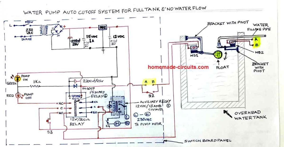
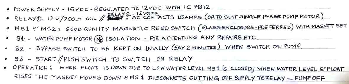
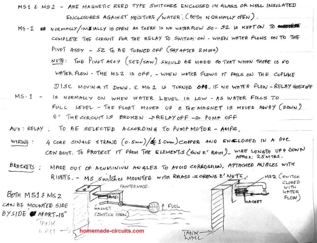
Using Pivoted Float Switch
In the above concept I have explained how to use a float switch device, intended to float on water, by rising and dipping in response to the water levels in the tank.
The following concept utilizes a different but very interesting approach which makes use of a float that is pivoted at end through hinges, and is positioned in water in a such a way that, it moves up an down using the pivoting hinge, in response to the eater levels. And during the process it activates and deactivates an attached reed switched device, which in turn causes the pump motor to switch ON and OFF.
The idea was contributed by one of dedicated members of this blog. The following pictures explain the detailed working of the system.
NOTE: The circuit also includes a dry run protection


Questions & Answers
Greetings…!!!
Hi dear Swagatham,
Really appreciate you for such extraordinary excellent circuit by you.Switching the 100mf capacitor to base emitter junction of bc547 is the only correction I’m doing.it was Really amazing circuit. Which type power supply we have to arrange for this circuit sir moreover can I use the readily available magnetic float switch for the same ?I’m going to desighn one pcb for this device but even a hobbyist can assemble on breadboard too.How can we solve the power failure to resume the on state again?any way?
Thank you,
Dr.Sison
Thank you Dr. Sison,
Glad you liked the circuit. Your modification is correct, the capacitor C2 must be placed between the base emitter of the NPN BJT.
However the value of this capacitor can be around 1uF.
Restoring automatically during power failure would mean adding an additional circuit.
Instead you can simply replace the push button with a 1uF/25V capacitor, in that case it will become an auto restoring circuit during power failures.
Hi Swagatam,
Thanks for your reply. How does the NPN transistor get power when C2 is connected? A Capacitor has an infinite resistance and will not allow any current to flow to the Collector of the NPN transistor.
Also, if I connected C2 across base/emitter of the NPN transistor, would it be parallel to R4?
Hi Vijay,
The power enters from the emitter of the PNP transistor, then passes through R3, and finally via the collector/emitter of the NPN transistor to ground.
If you connect C2 with the NPN transistor it is supposed to be right across the base and emitter pins of the NPN.
Thanks Swagatam. Does this mean, the Ic of NPN will be very low because it is supplied by Ib of PNP? My understanding is that base current needs to be very low to ensure adequate current (multiplied by gain factor) flows through the transistor. And this low Ic of NPN is just enough to keep the PNP ON…correct?
Yes, that’s correct! The Ic of the NPN depends on the value of the base resistor of the PNP. However, the base current is supposed to be calculated depending on the collector current. And the collector current should not exceed the maximum safe limit of the transistor. The NPN connects the base resistor of the PNP to ground allowing the PNP to get the required negative bias through the ground line.
Thank you!
Hi Swagatam,
I recently found your website and have been a great fan of your 555 projects.
I have a question in the Circuit Diagram of Float Switch Controlled Water Level Controller Circuit.
Well its specifically the connection between NPN transistor to a PNP transistor. When the button is pressed, the base of T3 is positively biased and turns it ON. Question is how does the voltage at the base of T4 go below 0.7v to turn it ON? And when T4 turns ON, how is the Vbe maintained below 12v-0.7v continuously to keep the relay activated?
And also, how did you decide the location of C2?
Thank you Vijay, glad you liked the projects here.
As soon as the push is pressed, the NPN conducts and pulls the base of the PNP transistor to ground through its collector/emitter pins. This causes the PNP also to switch ON. When this happens the voltage from the collector of the PNP is sent to the base of the NPN via R4. Due to this feedback through R4 both the transistor get latched and the relay is permanently switched ON even if the push is released.
C2 is supposed to be connected across the base/emitter of any one of the transistor, to avoid false triggering of the circuit. However the best place to connect C2 is across the base/emitter of the NPN transistor.
connecting floatswitch with esp the circuit diagram please
Hello Sir Swag,
How can i modify the above circuit to become a fully automatic? i want the relay to stay activated as long as the float switch is actuated and remain off as long as the float switch is in open position? a non-latching relay circuit?
should i just remove the switch-to-on and connect the R2 to positive rail? thanks!
Hello Amor, to operate the relay on reed activation, you can use a simple relay driver stage as shown below:
https://www.homemade-circuits.com/2012/01/how-to-make-relay-driver-stage-in.html
The transistor triggering source will connect with one terminal of the reed switch, while the other terminal of the reed will go to the positive line.
Also make sure to connect a small value capacitor across transistor base/emitter.
please give me good working semi automatic water level controller circuit diagram with pcb
distance between from sump to over head tank is app 60-65 feet
Below given are a few designs which you can study and modify as per your own specifications
https://www.homemade-circuits.com/?s=semi+automatic+water
sir, plz tell about how to design automatic distribution of water system using plc and name of the float switch used here.
Vignesh, presently I do not have the required design, I'll try to find it out if possible.
the float switch is a simple magnetic float with a reed switch sensor
Hi Swagatman,
I love your website and just wanted to say thanks for all your effort in sharing your ideas 🙂
I have built a water level indicator using a Arduino uno some LED's and some float switches, that works similar to this. A push button to start the pump and it stops automatically when the tank is full. Im not really an electronics person so writing a bit of code was easier for me than making circuits 🙂
Anyway i am learning some electronics from people such as yourself. THANKYOU 😀
Thanks so much Jason, that's very interesting, please feel free to inquire anything related to electronics and keep up the good work
Sir
can i use transformer-less power supply for this circuit.?
because previously i used transformer type power supply but transformer get faulty very often.
thanking you
Rohit, yes you can try it, in that case you can also think of replacing the relay with a triac (BTA41600)
sir
can i use transformer-less power supply for this circuit.?
thank you
could you suggest any circuit for 0-30mV power supply.
I don't have it presently, I'll look for it if possible.
Hello Swagatam,
Please Post a Capacitive/Body/Touch Sensitive Circuit can be applied on bicycle. Such device seen on car security system, When somebody come closer to car or a simple touch would trigger the alarm for 5 seconds.
How this type of alarm works, the alarm only trigger when somebody come closer (say 30cm) what type of sensor they use?
Hi Max,
You'll find it posted soon, thanks!
Hello Swagatam,
I'm glad to see that you accept my request and posted a circuit. And I see this as the trimmed down version of "Cheap Semi Automatic, Tank Water Over Flow Controller Circuit" which you posted 2 year ago, is it so ?
(sorry for being foolish about this question but I never feel shy to reveal my doubts ) Will this work by simply placing the probes inside the tank too ?
Thanks,
Praveen Raj
Hello Praveen,
Thank you! yes only the latch section from the previous circuit has been employed here. The simple configuration could be possible due to the involvement of a reed switch and also because the design is not fully automatic.
If only probes are used then you would have to go back to the previous design and include T1/T2 for the intended detection of the water level.
could you suggest any circuit to convert (0-20mv) to (0-10 volt)
that's remotely possible.