A stud finder is an electronic device specially created for scanning concrete walls and locating metallic objects, such as nails, bolts, pipes, hidden beneath the wall.
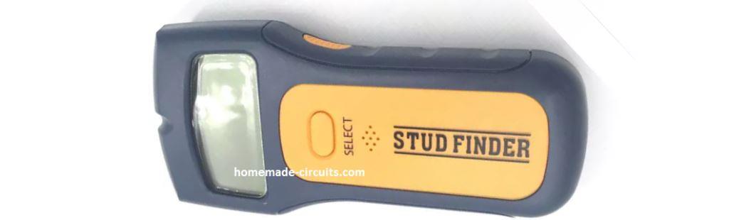
In the following post I have explained a very simple two-transistor metal detector that you can assemble in an afternoon or two and have fun with using for hours at a stretch.
The circuit shown below possibly will not find you a mine of gold, or any other treasure for example.
Nonetheless, it can help discover cabling and embedded nails in the walls, or metal pipes under the floor, and will cost you hardly anything to construct.
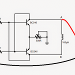
How the Circuit Works
Referring to the schematic below, the transistor Q1 (a 2N3904 NPN device) is configured as a simple LC oscillator circuit.
The values of the components L1, C3, C4, and C9 determine the operating frequency of the circuit.
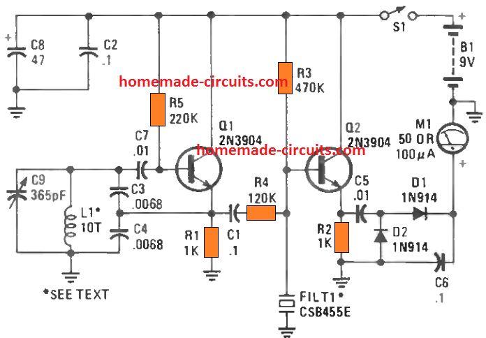
The oscillator's output is extracted via capacitor C1 and R4 and sent to to a 455-kHz ceramic filter.
As soon as the oscillator gets tuned to the filter's center frequency, the filter starts operating like a parallel tuned circuit and begins generating a high level 455 kHz signal at the junction of R3 and R4.
This tuned 455-kHz signal is then applied to the transistor Q2, set up as an emitter follower.
The signal output from Q2 (acquired from its emitter pin) is subsequently transformed to DC through rectifier diode D1,
After this, the frequency is fed to the indicator meter M1 (a 50- to 100-uA meter). The oscillator stage being tuned at extremely close to the the filter's center frequency, the meter shows the reading anywhere near mid-way of the scale.
However, as soon as any kind of metal object bigger than a BB (7mm) comes close to the loop, the meter's reading might show either a improvement or reduction, according to the specifications of metal.
The stud finder circuit will identify anything from a penny a couple of inches away or a D-cell battery at around 5 inches on ground surface.
How to Make the Search Coil
The search loop or the coil is wrapped over a small diameter former which is ideal for tracing smaller sized items from close range, however a bigger loop or coil could be made to locate larger metals, hidden deeper.
A plastic end cap for a 4-inch PVC sewer pipe (which is often available at nearly any plumbing supply counter) could be used as the coil bobbin for the search loop.
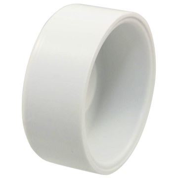
This is constructed by putting 10 tightly wound turns using 26 SWG super enamel copper wire.
This should be wound across the bottom part of the end cap and then fixed firmly using cello tape adhesive in place.
The circuit components could be assembled on a veroboard and should be encased inside a metallic box. Capacitor C9 could be just about any variable capacitor which you can salvage from and old radio.
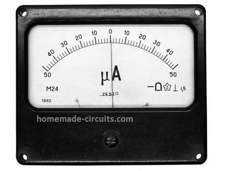
Meter Specifications
The indicator meter is an ordinary 50 µA ammeter as shown in the following image.
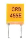
How to Select the Ceramic Filter
Many different 455-kHz ceramic filters had been experimented with in the circuit and almost all did actually perform correctly.
The search coil or loop needs to be positioned a minimum of one foot off from the unit's assembly box.
This separating distance should be implemented using a nonmetallic handle or shaft. A wooden dowel pole can be a nice option.
The search loop and the circuit inside the box could then be interconnected through a sprained set of two un-shielded wires.
How to Test
If for whatever reason you are unable to obtain a meter deflection while adjusting variable capacitor C9, the issue may be simply due to the oscillator stage which just might not be tuning at the filter's frequency.
To check the issue you could use a frequency meter unit could be and hook it up with the Q1 to determine exactly what signal (if any) may be existing.
Or, in case a frequency meter isn't accessible, you may work with a ordinary AM receiver and tune the circuits oscillator to the second harmonic.
Example, if the circuit's oscillator is running at 500 kHz, adjust your radio to 1 MHz you should be able to listen to the carrier transmission loud and clear.
If the oscillator's frequency tends to get extremely high, put a capacitance parallel to C9.
If you find the frequency transmission is too low, you may reduce the values of C3 and C4.
Additionally, In case the meter deflection doesn't rather arrive at the full scale range, you may try decreasing the value of R4.
And, if you see the meter needle banging hard at the full scale range, you can try increasing the value of R4 appropriately.
Through some trial and error, you should be able to soon figure out the most effective way of tuning the stud finder circuit for uncovering any desired size and type of metallic objects.
Adjusting the Sensitivity
The circuit's sensitivity can be enhanced by adjusting the tuning so that the meter settles at around 50 % on the dial in the absence of any metal near the search coil.
The proposed stud finder circuit will dig out ferrous and non-ferrous metals by triggering the meter to maximize in the presence of one and minimize with the other.

Questions & Answers
Hello sir, I am new in this field, and I take interest in making electronics and science projects. I am having a lot of difficulty on how to create an electronic circuit diagram with images. I have seen a lot on youtube, also seen in google sites. Please tell me what software the electronic circuit diagram of the image makes it with, please guide me.
Hukum, there are many online softwares that are available for drawing schematics.
Schematic drawing software online
thank you so much sir