• Skip to main content
  • Skip to primary sidebar

Homemade Circuit Projects

Need circuit help? Post them in the comments! I've answered over 50,000!

Blog | Categories | About | Hire Me | Contact | Calculators-online
You are here: Home / Audio and Amplifier Projects / Music Triggered Amplifier Speaker Circuit

Music Triggered Amplifier Speaker Circuit

Last Updated on May 15, 2026 by Swagatam 8 Comments

The circuit idea I have explained below enables a power amplifier loudspeakers to switch ON only when there's an input music available, otherwise it makes sure that the loudspeakers remain shut off. The idea ws requested by Mr. David Alda.

Table of Contents
  • Technical Specifications
    • The Design
    • Using LM386 as Music Amplifier
    • Function of Buzzer Coil

Technical Specifications

Your site is just awesome.

I'm hoping you can post a tweak to your post of 10-1-2013 entitled:

Sound Activated Automatic Amplifier Mute Circuit

I need the opposite of that circuit. What I need can be used in recording studios, broadcast studios, etc.

When the input is very low (or none), the output of the amp will be muted. When there is input sound, the amp will function un-muted. The amp needs to have enough power to power a computer type speaker at moderate to high volume levels.

As it will be used in real life:

When computer recording software (or a PC sound card) is not sending out any sound, the circuit will clamp the output so that zero noise is heard in the speaker in the studio. But when the recording software is sending out an input signal, the amp will function normally and drive the studio speaker at an adequate volume level.

On behalf of all those you have helped, thank you. May you be blessed in every way.

Is there any audio I can voice for you for free?

David Alda

Voice over talent & audiobook narrator
The Design

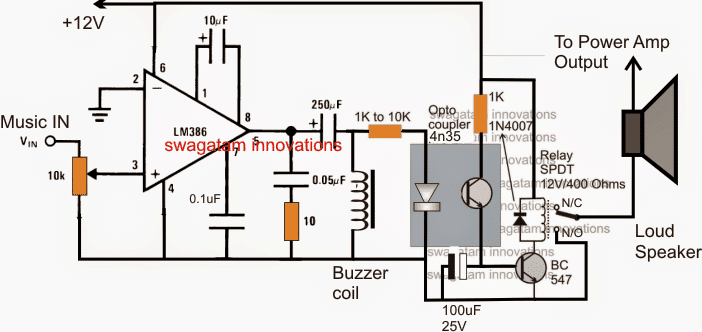
The requested circuit for implementing a music activated amplifier speaker can be witnessed in the figure above.

The idea looks pretty simple but consists of crucial stages which cannot be replaced by any other form of circuit stages.

The music feed (extracted from the power amp input) is applied to the input of an LM386 mini amplifier circuit set at a gain of 200, which is maximum gain for this IC.

The hi gain setting allows the amplifier to sense even the minutest level of input signals, although this may be set as per the users preference through the given input volume control pot.

Using LM386 as Music Amplifier

In the presence of a music input, the LM386 amplifies it to the required levels and the output is acquired at the output pin#8 of the IC through an AC coupling 250uF capacitor, and applied across an condenser inductor which should be preferably a "buzzer coil". You can see the image of a buzzer coil below:

buzzer coil for piezo tranducer

Function of Buzzer Coil

The buzzer coil makes sure that the amplified music is further boosted to higher levels in order to make it compatible with an opto coupler input LED.

The optocoupler 4n35 can be seen connected across the coil, the built in LED inside the opto responds to this music voltage and lights up which in turn switches ON the internal photo transistor of the opto.

The emitter of the photo transistor inside the opto now begins conducting so that the connected external relay driver transistor BC547 receives enough base drive to activate the relay.

The relay switches ON immediately in response to the above procedures and connects the power amplifier's output with the loudspeakers.

Conversely, in an absence of a music signal or insufficient music at the input, the LM386 and the output coil are unable to sustain any voltage at the output, which keep the opto and the relay driver stages switched OFF, the loudspeakers also stay off  because of this, until a legit music input is sensed.

The 100uF capacitor at the base of the BC547 transistor makes sure that the relay does not chatter in case the input carries a fluctuating or intermittent music signal.

You'll also like:

  • Make this Simple Buzzer Circuit with Transistor and Piezo
  • simplest 10 watt amplifier circuitSimple 10 Watt Amplifier Circuits using Transistors
  • audio clipper circuitAudio Clipper and Compressor Circuits Explained
  • The Perfect FM Radio Circuit using TDA7000 IC

Filed Under: Audio and Amplifier Projects Tagged With: Amplifier, Music, Speaker, Triggered

About Swagatam

I am an electronics engineer and doing practical hands-on work from more than 15 years now. Building real circuits, testing them and also making PCB layouts by myself. I really love doing all these things like inventing something new, designing electronics and also helping other people like hobby guys who want to make their own cool circuits at home.

And that is the main reason why I started this website homemade-circuits.com, to share different types of circuit ideas..

If you are having any kind of doubt or question related to circuits then just write down your question in the comment box below, I am like always checking, so I guarantee I will reply you for sure!

Previous Post: « Simple RGB LED Color Mixer Circuit using LM317 IC
Next Post: PWM Inverter Using IC TL494 Circuit »

Reader Interactions

Questions & Answers

Total Posts: 8
Newest Oldest
Neeraj Kumar
May 24, 2021 • 5 years ago #90509

Music Triggered Amplifier speaker. I am actually looking for something that can turn off the amplifier power in case there is no music played with in 5 minutes (Variable) after turning on the amp. This way we can build a kind of eco mode on to the amp. The amp will continue to be on as long as there is a input signal with any one of the pre outputs. A similar one on the preamp will also help.These days most higher end brands incorporate an eco mode for power saving

Reply
SwagatamAdmin
May 24, 2021 • 5 years ago #90518

You can try the following circuit, but it will not give 5 minute delay, it will give not more than 30 second delay switch OFF

Music off speaker off circuit eco mode circuit

Reply
johnnytheangel1
July 10, 2016 • 10 years ago #42470

can I use this (Music Triggered Amplifier Speaker Circuit) to switch on LEDs instead of speakers, does the music input need to come from amp or line out/headphone thank you,

Reply
SwagatamAdmin
July 10, 2016 • 10 years ago #42483

yes, you can use any type of load with the relay instead of the speaker.
amplified input is not required since the LM386 is itself an amplifier and is incorporated for amplifying even small signals at the input

Reply
jindro
January 2, 2018 • 9 years ago #57290

sir can I use +vcc and -vcc here and if yes how would I do that?

Reply
SwagatamAdmin
January 2, 2018 • 9 years ago #57292

Jindro, you can use a normal +/- single supply across the lines which are connected with pin#6 and pin#4 of the IC LM386

Reply
jindro
January 2, 2018 • 9 years ago #57293

tnk u for the reply Sir! I’m a newbie in audio amp making and someone say that it will be better if I have a dual powerful for an audio amp, but I’ve only seen a + and grnd on power input. how would I connect +vcc, -vcc, and GND in it Sir?

Reply
SwagatamAdmin
January 2, 2018 • 9 years ago #57296

Jindro, you can use dual supply for your power amplifier unit, for the above shown LM386 music detector circuit dual supply is not required…..

Reply

Need Help? Please Leave a Comment! We value your input—Kindly keep it relevant to the above topic! Cancel reply

Your email address will not be published. Required fields are marked *

Primary Sidebar

My YouTube Channel

Circuit Simulator: Draw and Simulate Schematics

circuit simulator image

Categories

  • Arduino Projects (95)
  • Audio and Amplifier Projects (134)
  • Automation Projects (18)
  • Automobile Electronics (104)
  • Battery Charger Circuits (90)
  • Datasheets and Components (109)
  • Electronics Theory (151)
  • Energy from Magnets and Earth (43)
  • Games and Sports Projects (11)
  • Grid and 3-Phase (20)
  • Health related Projects (27)
  • Home Electrical Circuits (13)
  • Indicator Circuits (16)
  • Inverter Circuits (98)
  • Lamps and Lights (161)
  • Meters and Testers (72)
  • Mini Projects (28)
  • Motor Controller (68)
  • Oscillator Circuits (30)
  • Pets and Pests (15)
  • Power Supply Circuits (91)
  • Remote Control Circuits (50)
  • Security and Alarm (65)
  • Sensors and Detectors (107)
  • SMPS and Converters (46)
  • Solar Controller Circuits (62)
  • Temperature Controllers (44)
  • Timer and Delay Relay (51)
  • Voltage Control and Protection (44)
  • Water Controller (37)
  • Wireless Circuits (31)

Subscribe to get New Circuits in your Email

Other Links

  • Privacy Policy
  • Cookie Policy
  • Disclaimer
  • Copyright
  • Videos
  • Sitemap

People also Search

555 Circuits | 741 Circuits | LM324 Circuits | LM338 Circuits | 4017 Circuits | Ultrasonic Projects | SMPS Projects | Christmas Projects | MOSFETs | Radio Circuits | Laser Circuits | PIR Projects |

Recent Comments

  • Swagatam on Room Air Ionizer Circuit – For Pollution Free Living
  • Swagatam on Understanding Motorcycle Voltage Regulator Wiring
  • Swagatam on Analogue Water Flow Sensor/Meter Circuit – Check Water Flow Rate
  • Swagatam on How to Replace a Transistor (BJT) with a MOSFET
  • SA on How to Replace a Transistor (BJT) with a MOSFET

Social Profiles

  • Twitter
  • YouTube
  • Instagram
  • Pinterest
  • My Facebook-Page
  • Stack Exchange
  • Linkedin

Calculators

  • ZVS Induction Heater + Tank Calculator Tool
  • Zener Diode Calculator
  • Wire Current and Thickness Calculator (Ampacity Calculator)
  • Voltage Divider Calculator
  • Transistor Base Resistor Calculator
  • Transistor Astable Multivibrator Calculator
  • TL431 Calculator
  • Solar Panel, Inverter, Battery Calculator
  • Ferrite Core Air Gap Calculator Tool
  • Parallel MOSFET Calculator Tool: How to Connect MOSFETs in Parallel Safely
  • LC Resonance Calculator for EV Battery Charger Circuits
  • LED String Series Resistor Calculator
  • PFC (Power Factor Correction) Calculator Tool: 3kW
  • Passive Power Factor Correction (PFC) Calculator
  • LM567 IC Calculator Tool
  • SMPS Flyback Boost Converter Calculator
  • Shunt Resistor Calculator for Ammeters
  • SCR and Triac Gate Resistor Calculator
  • Battery Back up Time Calculator
  • Boost Converter Calculator (Non-Isolated)
  • Bootstrap Capacitor Calculator
  • Buck Converter Calculator
  • Buck-Boost Converter Calculator
  • Capacitance Reactance Calculator
  • DCM Flyback Transformer & Wire Gauge Wire Size Calculator Tool
  • Filter Capacitor Calculator
  • IC 4047 Calculator (Frequency and PWM)
  • IC 4060 Calculator
  • IC 555 Astable Calculator
  • IC 555 Monostable Calculator
  • IC SG3525, SG3524 Calculator
  • Inductance Calculator
  • Induction Heater Inductor and Resonant Frequency Calculator
  • Induction Heater Work Coil Calculator
  • Inverter LC Filter Calculator
  • LC Resonance Calculator
  • LED Current Calculator
  • LM317, LM338, LM396 Calculator
  • NAND/NOT Gate RC Values Calculator
  • NOT, NAND Gate Frequency Calculator
  • Notch Filter Calculator Tool
  • Ohm’s Law Calculator
  • Phase Angle Phase Shift Calculator
  • Power Factor (PF) Calculator
  • RC Filter Calculator
  • Reactance Calculator
  • Sine Table Calculator for SPWM Arduino Code
  • Small Signal Transistor(BJT) and Diode Quick Datasheet
  • SMPS Calculator for Toroidal Ferrite Transformers
  • SMPS Flyback Transformer Calculator – Design by Target Duty Cycle
  • TL431 Calculator
  • Op-Amp Hysteresis Resistor Calculator

© 2026 · Swagatam Innovations