• Skip to main content
  • Skip to primary sidebar

Homemade Circuit Projects

Need circuit help? Post them in the comments! I've answered over 50,000!

Blog | Categories | About | Contact | Calculators-online
You are here: Home / Audio and Amplifier Projects / Sound Activated Automatic Amplifier Mute Circuit

Sound Activated Automatic Amplifier Mute Circuit

Last Updated on May 5, 2022 by Swagatam 5 Comments

The following article presents a simple sound operated/activated amplifier muting circuit which enables the amplifier to silence itself as soon a voice or an external sound occurs across the detector MIC. The circuit was requested by Mr. Seok Sothea.

Table of Contents
  • Technical Specifications
  • The Design
  • Circuit Diagram

Technical Specifications

I want to make a circuit about voice interrupt music..this circuit consists of two input, audio input and mic, and one output to amplifier.

First, the input from any audio player. While playing, if their is any sound into microphone, audio will become mute. After the sound from microphone is stop, the audio will be increasing its volume rapidly to its initial volume for some seconds. So, can you guide me some sir?

This circuit is connected directly to amplifier, if possible it uses power supply from amplifier. I don't know that it is useful or not.

But just my idea, i think it make easy for one who control and playing the music, like in the party, club, FM station, or anywhere that play music as background sound, they don't need to decrease or increase the volume of music when they talk and stop to talk on microphone.

The Design

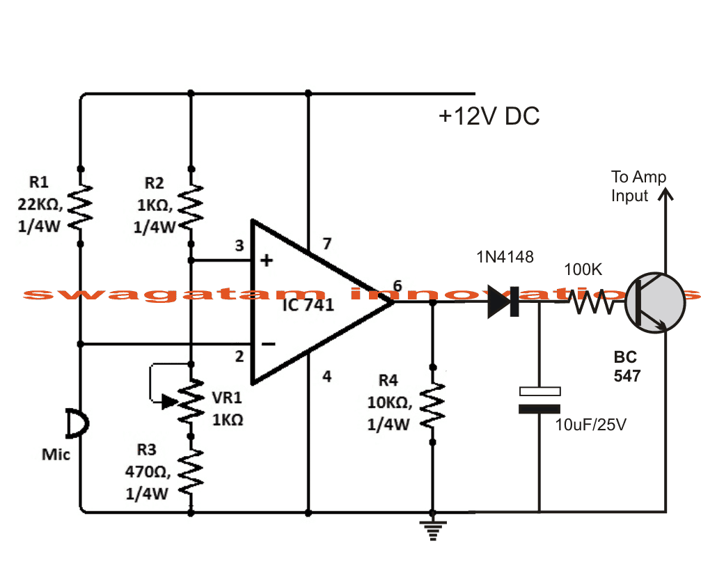
Referring to the shown sound activated amplifier mute circuit below, we see only a single opamp being used for the proposed actions.

The functioning may be understood with the help of the following discussion:

When a external sound hits the MIC, depending upon the setting of VR1, if this sound is strong enough to pull pin#2 potential below the set potential of pin#3, the output instantaneously goes high.

This momentary high charges up the 10uF/25V capacitor and also triggers the NPN BC547 transistor.

The transistors instantly pulls the amplifier input to ground causing the required silencing or muting of the amplifier output.

The above situation persists for a few seconds depending on the values of the 10u cap and the 100k base resistor.

The above may be altered as per requirement for either raising or reducing the mute period of the amplifier.

As the 10uF discharges, the transistor gradually inhibits its conduction thereby causing an exponential or slow rising switch ON of the amplifier until it restores and reaches its full volume.

Circuit Diagram

ampmutecircuitsoundoperated


voiceactivatedmikemutecircuit


You'll also like:

  • 1.  Guitar Distortion Generator Preamplifier Circuit
  • 2.  Ding Dong Bell Circuit that Saves Electricity
  • 3.  5 Simple Audio Mixer Circuits Explained
  • 4.  Mp3 Player Using DF Player – Full Design Details
  • 5.  Simple Tone Control Circuits
  • 6.  Guitar Amplifier Circuit with Fuzz Effect Genertaor

About Swagatam

I am an electronics engineer with over 15 years of hands-on experience. I am passionate about inventing, designing electronic circuits and PCBs, and helping hobbyists bring their projects to life. That is why I founded homemade-circuits.com, a website where I share innovative circuit ideas and tutorials. Have a circuit related question? Leave a comment.... I guarantee a reply!

Previous Post: « Pure Sine Wave Inverter Circuit Using IC 4047
Next Post: Diwali, Christmas 220V Lamp Chaser Circuit »

Reader Interactions

Comments

  1. Seok Sothea says

    October 7, 2013 at 1:47 pm

    I have learnt alot from you sir. Thanks!

    Reply
  2. Seok Sothea says

    October 6, 2013 at 3:54 pm

    Thank much sir!. You have helped me alot. One more question sir. Can the sound from mic be changed since you have connected from the output of comparator? Can i connect directly from mic to relay sir?

    Reply
    • Swagatam says

      October 7, 2013 at 5:49 am

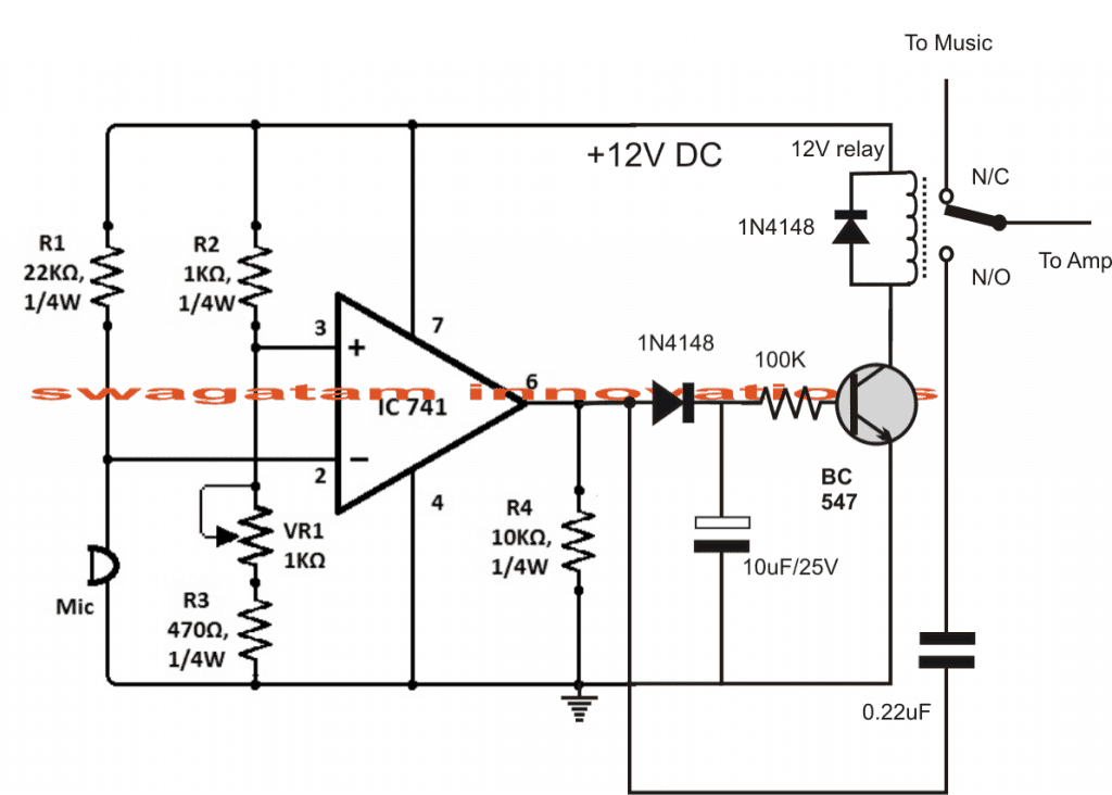
      You are welcome Seok, you are right, please take the mic connection directly from pin#2 and not from pin#6 output as wrongly shown in the diagram.

      Reply
  3. Seok Sothea says

    October 3, 2013 at 3:51 am

    Wow! Very quick. Thank you very much sir! But i miss one point to tell you.sorry sir. I mean there is one sound that go out to amplifier. when the music become mute. The voice from mic goes into amplifier instead. Could it possible sir. Sorry again for missing this point.

    Reply
    • Swagatam says

      October 3, 2013 at 5:40 am

      I have updated the modifications, please check it out.

      Reply

Need Help? Please Leave a Comment! We value your input—Kindly keep it relevant to the above topic! Cancel reply

Your email address will not be published. Required fields are marked *

Primary Sidebar

Subscribe to New Circuit Ideas

Categories

  • Arduino Projects (87)
  • Audio and Amplifier Projects (132)
  • Automation Projects (17)
  • Automobile Electronics (101)
  • Battery Charger Circuits (83)
  • Datasheets and Components (104)
  • Electronics Theory (143)
  • Free Energy (37)
  • Games and Sports Projects (11)
  • Grid and 3-Phase (19)
  • Health related Projects (25)
  • Home Electrical Circuits (12)
  • Indicator Circuits (14)
  • Inverter Circuits (87)
  • Lamps and Lights (142)
  • Meters and Testers (69)
  • Mini Projects (46)
  • Motor Controller (64)
  • Oscillator Circuits (27)
  • Pets and Pests (15)
  • Power Supply Circuits (108)
  • Remote Control Circuits (50)
  • Security and Alarm (64)
  • Sensors and Detectors (101)
  • Solar Controller Circuits (59)
  • Temperature Controllers (42)
  • Timer and Delay Relay (49)
  • Transmitter Circuits (29)
  • Voltage Control and Protection (37)
  • Water Controller (36)

Calculators

  • Battery Back up Time Calculator
  • Capacitance Reactance Calculator
  • IC 555 Astable Calculator
  • IC 555 Monostable Calculator
  • Inductance Calculator
  • LC Resonance Calculator
  • LM317, LM338, LM396 Calculator
  • Ohm’s Law Calculator
  • Phase Angle Phase Shift Calculator
  • Power Factor (PF) Calculator
  • Reactance Calculator
  • Transistor Astable Calculator
  • Transistor base Resistor Calculator
  • Voltage Divider Calculator
  • Wire Current Calculator
  • Zener Diode Calculator
  • Filter Capacitor Calculator
  • Buck Converter Calculator
  • Boost Converter Calculator
  • Solar Panel, Inverter, Battery Calculator
  • Wire Current Calculator
  • SMPS Transformer Calculator
  • IC SG3525, SG3524 Calculator
  • Inverter LC Filter Calculator

People Also Search

555 Circuits | 741 Circuits | LM324 Circuits | LM338 Circuits | 4017 Circuits | Ultrasonic Projects | SMPS Projects | Christmas Projects | MOSFETs | Radio Circuits | Laser Circuits | PIR Projects |

Recent Comments

  • Swagatam on Real MPPT Solar Charger Circuit Using Arduino, LCD, and Manual/Auto Switch
  • Obaidullah Khan on Real MPPT Solar Charger Circuit Using Arduino, LCD, and Manual/Auto Switch
  • Swagatam on 2 Compact 12V 2 Amp SMPS Circuit for LED Driver
  • Alan Bishop on AC Motor Speed Controller Circuits using Back EMF
  • Swagatam on Real MPPT Solar Charger Circuit Using Arduino, LCD, and Manual/Auto Switch

Company

  • Privacy Policy
  • Cookie Policy
  • About Me
  • Contact
  • Disclaimer
  • Copyright
  • Videos
  • Sitemap

Social Profiles

  • Twitter
  • YouTube
  • Instagram
  • Pinterest
  • My Facebook-Page
  • Quora
  • Stack Exchange
  • Linkedin
  • © 2025 · Swagatam Innovations