In this article I have explained regarding a motorized sun shade circuit which can be used for achieving an automatic motorized extension and retraction of sun shades or hoods.
The idea was requested by Mr. Sriram KP
Circuit Objectives and Requirements
- I have made wireless water tank controller with manual on-off switch, automatic steps light, soft switch room lights-fan controller, balcony timer lights.
- Now my home is partially like iron man home... 😀 Thanks to u lot. Now I like to make a motorized sun shade to my home balcony.
- Now am manually rolling the screen. I want to make it motorized. Could u pls help me out with a circuit?
- Am having a motor and a driver for it. I have to control the motor driver with the relay with a push to on.
- The motor have to run front and back ( to roll the screen up and down)with two push-to-on switch for 10 seconds.
- Once I press the "up" push-to-on switch means the motor should run for 10seconds (the screen will roll up) and should stop. and "up" switch should not work again( bcoz the screen is already rolled up).
- And now down switch should work now to roll down. And "down" switch should also have the same condition( should not work again, bcoz already rolled down) Thanks.
Circuit Diagram
The Design
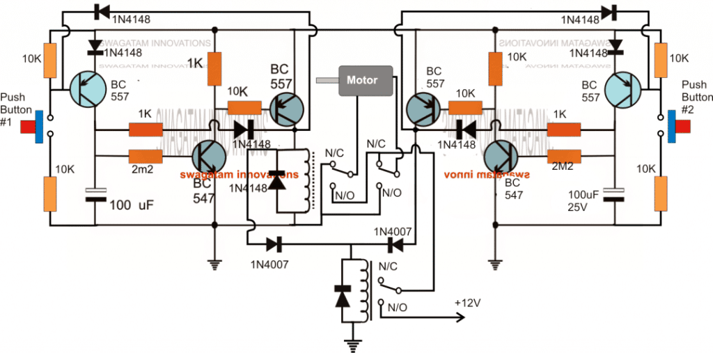
The proposed automatic motorized sunshade timer circuit can be seen in the above diagram.
Basically the design is made up of two transistor timer circuits using pairs of complementary NPN (BC547) and PNP (BC557) transistors. Two identical stages can be seen on either sides of the motor consisting the individual push buttons for the triggering.
The BC557 associated with the relay along with the complementing BC547 transistor forms the timer circuit in conjunction with the 2M2 resistor and the 100uF time determining components.
The other BC557 at the extreme ends of the circuit are included to implement the disabling of the push buttons once these are pressed, meaning once any of the push button is pressed the BC557 associated with it is disabled with the positive feed back signal from the relay driver BC557 collector.
This makes sure that the push buttons can be pressed only once during the triggering, and the subsequent pressing produces no effect until the time is elapsed and the timer is switched OFF
Now let's see how the relays become responsible for executing the motor reverse forward actions in response to the push button activation.
When power is applied to the circuit, the relay situation can be expected to be exactly as indicated in the diagram, that is at the N/C contacts and in the standby position.
The motor stays inactive because the lower relay contacts is not supplying the required positive to the motor via the upper DPDT relay contacts.
Let's assume the left push button #1 is pressed. This instantly activates the DPDT relay associated with the left timer circuit stage.
The lower SPDT also activates through 1N4007 diode link, causing all the relay contacts closing at their respective N/O states.
This action provides the required supply to the motor and allows it to the rotate towards the corresponding direction. The timer begins counting and after the stipulated time is over the relays are switched OFF, halting the motor.
Assuming the above procedures caused the motor to rotate clockwise, implies that pressing push#2 should cause the motor to rotate anticlockwise.
When push button#2 is pressed the right side timer is activated, however this time the DPDT relay does not react and continues to be at the N/C, but the lower SPDT surely activates providing the positive supply to the DPDT relay contacts.
With the DPDT across the N/C contacts allows the motor to get a reversed voltage causing it to rotate in the anticlockwise direction.
Design Flaw
Although the above explained motorized sun shade timer circuit looks great, it has a technical drawback.
The drawback lies in the fact that the push button are disabled only while the relevant timer is counting, and is enabled as soon as the timer has stopped counting or is reset.
This situation makes the push buttons vulnerable to a repeat triggering at the wrong side causing undesired loading of the motor.
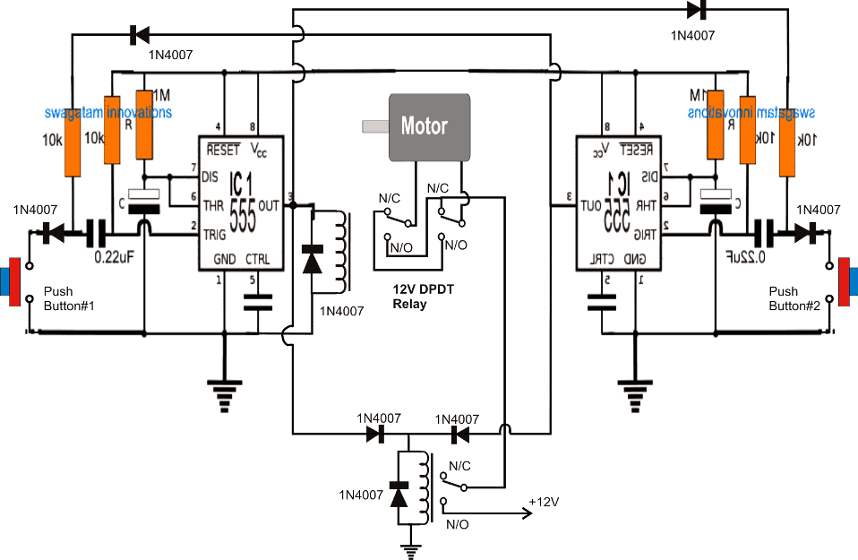
An identical design using the IC 555 solves this issue and ensures a permanent disabling of the push button once the associated timers have stopped counting.



Questions & Answers
https://images.app.goo.gl/2CtpaFK8zrdyMgz66
its normal 12 volt relay
Ghulam, for further discussions, you can post your questions under this article:
https://www.homemade-circuits.com/simple-remote-controlled-curtain-open-close-circuit/
It is still not opening. Show me ay online link…
https://images.app.goo.gl/xLBs9zwpEfpku32dA
sir plz check now
It is still not opening….
sir this is 8 pin dpdt relay,
 &tbnid=HiaSKGp6WYe-8M&vet=1&imgrefurl=https%3A%2F%2Fwww.pinterest.com%2Fpin%2F9851692908437077%2F&docid=XYg31QDX1O2_ZM&w=387&h=255&source=sh%2Fx%2Fim%2Fm1%2F2&kgs=886e9fa6e3c0d5a8&shem=abme%2Ctrie
this is 6 pin 30 amp relay,
https://images.app.goo.gl/DkAMXKPd2PCzfcNj6
Hi Ghulam, the second link is not opening….please check.
sir i have both relays, dpdt 8 pin 12 volt with base 12 A, and spdt 30amp 6 pin 12 volt,
Ghulam, without seeing the pinout details of the relays, it is not possible for me to draw the diagram…
Please show its image or a link to its image, with pinout details…
thank you sir, sir i need your one more support regatding this diagram, sir if you dont mind can you send me diagram with orginal picture of both relays with connectivity plz…its humble request plz
Hi Ghulam, which DPDT and SPDT relays do you have with you, please provide their datasheets.
no sir i didnot received notification or mail, yes sir i want to make remote control curton open close….thank you sir i am waiting
Hi Ghulam,
Are you getting the replies now in your email ID? Please let me know…
I will give you the circuit diagram tomorrow.
yes sir email received, waiting for circut diagram, thanks
Ghulam, here’s the circuit for a remote controlled curtain open/close circuit using only 2 relays.
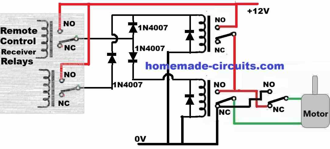
The upper right relay is an SPDT relay, the lower right relay is a DPDT relay:
hello sir, sir i assembled this circut with 555 ic, have both relays as well, but i dont know how to make relays connections, if you dont mind plz provide me actual picture of both relays and show me the connectivity plz, its request plz
Hello Ghulam,
Can you please tell me what exactly are trying to build, is it a remote controlled curtain open/close system?
If yes, then I can do it without any circuit, just by using 3 relays.
I had informed you about this 1 week ago, may be you did not see that response.
Let me know if you want that circuit using only 3 relays…
Hello sir, i read this article, i think this circut will help me for curtons project with push button. First i will try this one, after that make remote with rf module….sir plz send me complete and final diagram of this project plz
Hello Ghulam,
sure, you can try it, but make sure to have a current limiter for the power supply input current to the motor, so that if your timer is not perfectly accurately then the motor might stop little late after the curtain is fully closed or open, this might over-load the motor, so having a current limiter will prevent the motor from overloading.
Sir can you add overload feature. And also as per diagram i could’t get relay connections, because there us 3 n/c and 3n/o points, relays are 3 or 2, plz guide
There are two relays only, the upper relay which is wired with the motor is DPDT relay and the lower one is an SPDT relay…
Also in diagram there is 2 relays used, moter 2 wires connected with n/c 3 points same n/o, is there 3 relays? Plz guide me
Only two relays are used, the upper one is a DPDT relay and the lower one is the SPDT relay….
Sir is it possible add overload feature in this and update me. Or i will try with VR and set the time for both side……plz suggest me
Ghulam, overload feature will need to be added in the power supply, or yo can use a LM317 current control with your existing power supply and limit the current…
Hi Swagatam, good job you are doing with these circuits. Please help with a design for wireless motorised projector screen receiver circuit. The control unit of the projector was missing. The remote and the screen unit exist but without the control unit. Kelvene M. Salk1deo@gmail.com
Thanks Yusuf, you will have to provide all the technical details of the control unit, only then I would be able to suggest anything useful…
Now it is working when I placed 10uf. 0.22uf and 4.7uf is not working. Then can I use 1N4148 in all places instead of 1N4007?
yes, you can use it, since the relays are not too heavy
Hi, I tired the above circuit. When I pushed the either of the push switch, the motor didnt run. So when I checked the circuit, the 0.22uf not allowing the -ve trigger supply to the pin2. so I removed the 0.22uf and connected the diode to the pin-2 without 0.22uf. Then I tested the circuit again. Now when I pushed the either of the push switch, the motor also rotating either of the sides for the particular time which I set. Now whats the issue is, When I push the push switch-1, the motor rotating clockwise for particular time and stops. Again, when I push the push switch-1 means, the motor rotating clockwise. But it should not rotate in clockwise. That switch should be in In-active status until I press the push switch-2 to rotate the motor in anti-clockwise. Pls help..
Hi, It's because you removed the 0.22uF capacitor…these capacitors are specifically placed to ensure that the relevant switches remain disabled until the opposite side switch is activated.
If 0.22uF is not working, try increasing it to 4.7uF or 10uF…positive will go towards pin#2
hI SWAGATAM,
need help builda Mains operated LM386 Amplifier for plugnplay mobile or Laptop. USed capacitor power supply (9v @500mA). DEVICE surely fry, if directly connected to it. How to isolate mains voltage from device? tiny audio transformer o rany other home-made idea? Post a Tiny mains(isolated) LM386 amplifer, without adapter or x former,.
Hi Max,
the easiest way is to remove the circuit board from a cellphone charger unit which may be lying extra in your cupborad, you can use this circuit for driving the LM386 amplifier nicely.