This door controller circuit works in this way: Initially the door is in the closed state. When a push button is pressed, the door begins opening until it reaches the end of the course. When it reaches the end, it automatically reverses its direction and now the door begins closing. It keeps moving until it is fully closed and the whole circuit shuts off.
The circuit was requested by Mr. David.
Here's the specifications of the circuit, as required by Mr. David.
Circuit Objective
I'm searching for a circuit design that can automatically open and close a door with a single button press. Imagine if your garage door opener could begin its opening cycle with a push of a button, and as soon as the door reaches its completely open position, immediately reverse course to close it. To close the door, there would be no need to use a different button.
How the Circuit Works
If you do not want to read the whole description below, you can watch the following video instead:
At the initial resting state, the door is in the closed state. In this state the Limit#1 switch is depressed causing the latch circuit formed by T1 and T2 to remain disabled.
The T1, T2 latch circuit remains turned off simply because, in the closed state the door mechanism keeps Limit#1 switch closed, causing T3 to remain switched ON.
With T3 switched ON, causes the feedback voltage between R3 to R5 to cut off so that the T1, T2 latch cannot work.
In this condition, the Relay#2 remains switched OFF with its contacts resting in the N/C position. Due to this, the supply to the motor via the DPDT relay#1 is cut-off, and the motor cannot operate.
Also, the DPDT relay in this position has its pair of contacts towards the N/C points. The motor is wired to the DPDT relay contacts, such that, the N/C contacts of the relay keeps the motor configured to move towards the opening mode.
However, since relay#2 is at the N/C contacts the motor supply remains cut-off and the entire circuit along with the motor remains deactivated.
T4 is also switched OFF because the limit#2 switch which is at the other end is deactivated, so T4 cannot conduct and it remains shut off.
So, all in all the whole door controller circuit is disabled, but in a standby mode.
Now, if the push button is pressed, it forces T1 and T2 to conduct, but T1, and T2 still cannot latch up, because the door is still pressing the limit#1 switch causing T3 to remain turned ON and keep the R5, R3 feedback disabled.
However, within a second after the push button is pressed, T1, T2 are forced to turn ON causing the relay#2 to activate (contacts to N/O), which allows the motor to start moving.
This instantly releases limit#1 switch, allowing T1, T2 to latch, so that now relay#2 can remain turned ON even if the push button is released.
The motor now keeps moving the door until the door is fully open. At this point limit#2 switch is depressed by the door mechanism.
This turns ON T4 via R8, causing relay#1 to flip to its N/O pair of contacts, which in turn causes the motor to automatically reverse its rotation. The door now starts closing.
However at this point, limit#2 switch is quickly released, which means the T4 could turn off causing the motor to halt abruptly. But this does not happen due to the presence of R8 and C2 which work like a delay OFF timer and holds T4 turned ON until the door has finished closing fully.
Once the door is fully closed, limit#1 switch is pressed turning ON T3, which yet again breaks the latch causing T1, T2 and the relay#2 to shut off. Relay#2 contacts now move towards its N/O points cutting off power to the motor.
The door halts completely, and settles down at its initial closed position, until the push button is pressed again.
However, at this point when the door has just closed, there might be a possibility of T4 still remaining turned ON for a couple of seconds, because of some charge left inside C2.
In this position the DPDT relay contacts are still at its N/O position, which means the motor wires are still configured to be in the closing mode. So in this position the motor will not respond to the push button.
Therefore, once the door has closed, please do not press the push button immediately. Wait for a couple of seconds and then you can press the push button to open the door again, if required.
The LED1 is actually positioned exactly for this indication. As long as LED1 is ON, it shows that T4 and the DPDT relay#1 are still ON, and the motor is not ready for the opening the door in response to the push button pressing.
Also, make sure to dimension the R8, C2 values such that it turns OFF relay#1 after the door is fully closed, maybe a couple of seconds after the door is fully closed, as indicated by LED1.
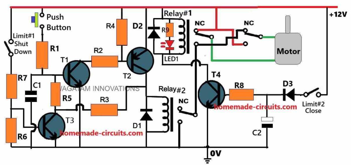
Circuit Diagram
Parts List
- All resistors are 1/4 watt CFR.
- R1, R9 = 1k
- R3, R8 = 100k
- R2, R4, R5, R6, R7 = 10k
- Capacitors
- C1 = 0.47uF
- C2 = 2200uF / 25V (needs adjustment as explained in the above explanation)
- Semiconductors
- D1, D2, D3 = 1N4007
- T1, T3 = BC547
- T2 = 2N2907
- T4 = TIP122
- LED1 = Red LED 5mm 20 ma.
- Relay#1 = 12V DPDT relay 40 amp contacts.
- Relay#2 = 12V SPDT relay, 40 amp contacts.
- Limit switches can be magnetic reed switches.
- Push button can be any small push button
How to Build
Step#1: Transistor Handling:
First identify the base, collector and the emitter pins of each transistor (T1, T2, T3, T4) using the datasheet or a multimeter.
Ensure that the transistors are placed properly to avoid incorrect biasing, which could damage the circuit.
Step#2: Resistor Placement:
Use the resistors with appropriate wattage ratings (typically 1/4W for small circuits).
Solder the resistors close to the respective transistors to minimize noise and ensure stable operation.
Step#3: Capacitor Placement:
Place the C1 near T1 to ensure the push buttons debounce timing is stable.
Use the ceramic capacitors for C1 and C2 as they are reliable for small-signal applications.
Ste#4: Relay Mounting:
Use relays with 12V coils and appropriate contact ratings for your motor's current and voltage.
Mount the relays securely on the PCB or the relay base to avoid vibration-related disconnections.
Step#5: Diode Orientation:
Connect the cathode (marked with a stripe) of diodes D1,D2,D3 to the positive side of the circuit.
These diodes protect the circuit from back EMF generated when the relays or motor switch off.
Step#6: Push-Button Installation:
Use a high-quality push button with having sufficient debounce resistance.
Ensure it is mounted in a way that is easily accessible and free from physical obstructions.
Step#7: Limit Switch Placement:
Limit#1 should be installed at the door's fully open position and Limit#2 at the fully closed position.
Wire them securely to ensure that they operate reliably under mechanical stress.
Step#8: PCB Layout:
Keep the high current traces for the motor and relays wide to handle the required current.
Separate the high power and low-power sections on the PCB to reduce interference.
Ste#9: Power Supply:
Use a regulated 12V DC power supply with sufficient current capacity. For example use a 2A supply would handle most small motors.
Step#10: Testing:
After assembly use a multimeter to check for shorts between the power supply rails.
Test the circuit with the motor disconnected to ensure relays and LEDs operate correctly.
Calculations
Base resistor formula:
Rb = (Vin - Vbe) / Ib
where
- Vin is the input voltage,
- Vbe is the base-emitter voltage (usually 0.7V for silicon transistors),
- and Ib is the base current.
Ib can be calculated as:
Ib = Ic / hFE
- where
- Ic is the collector current
- and hFE is the current gain of the transistor.
Capacitor timing formula:
t = R * C
where
- t is the time constant in seconds,
- R is the resistance in ohms,
- and C is the capacitance in farads.
Motor current formula:
I = P / V
where
- I is the current in amperes,
- P is the motor power in watts,
- and V is the supply voltage in volts.
Relay selection formula:
Irelay > Imotor
where
- Irelay is the relay's current rating
- and Imotor is the current required by the motor.
Diode rating formulas:
Vr > V
where
- Vr is the diode's reverse voltage rating,
- and V is the supply voltage.
Id > Imotor
where
- Id is the diode's forward current rating
- and Imotor is the current required by the motor.


Questions & Answers
Achei que poderia usar um ci com up e down para controlar os pulso
Ok, please let me check your requirement again, I will try to figure it out soon, hopefully, I will let you know once I do it…
Bom noite, amigo preciso da sua ajuda para um projeto seguinte, um circuito com dois botões de pulso (+) e (-), para controlar dois relé, K1 e K2 funcionando da seguinte forma…
Quando eu de o primeiro pulso no botão (+) manter acionado o rele K1
Quando eu de o segundo pulso do botão (+)desliga o rele K1 e liga o rele K2
Quando eu de o terceiro pulso no botão (+) permanece acionado o rele k2 e acionando o rele k1
E quando de pulso no botão de menos (-) o inverso do processo
First time Press button#1: Relay K1 on, Relay K2 OFF
Second time Press button#1: Relay K2 on, Relay K1 OFF
Third time Press button#1: Relay K1 on, Relay K2 OFF
Is this correct?
After this what happens when button#2 is pressed in the same sequence, please explain step wise.
Hello Rosi,
Your application looks difficult using discrete parts, especially the reverse movement of the sequence. I think it will require an Arduino based design, and unfortunately I am not good with Arduinos.
Please explain the circuit working in more detail so that the students will understand the circuits more easily and also they will stay more time on the page. It is a suggestion if it is easily possible.
May you kindly explain that when in initial stage when T1 and T2 are disabled and T3 is conducting through the Limit swith no 1. What will be the current path of collector of T3 transistor . Waiting for ur kind response. Thankd.
When Limit#1 is depressed, T3 will be conducting and it will ground the latching feedback coming from the T2 collector towards the base of T1, via R3, R5. Due to this the T1 and T2 will turn OFF and become disabled, causing the motor supply to be cut off and disabled.
And plz add timer feature also. Like once press up push button, when curton folded moter auto off. And once we press down buton, after down moter off……plz
Ok, but should this be through a remote control or through wiring?
Hello sir, i need your support. I want to make curten opener and closer with one moter and two (up and down) buttons. Plz provide me circut diagram plz
Hello Ghulam, do you want it to be remote controlled or wired?
Sir its good if worked with remote….
Hi Ghulam, I will try it and let you know if I am able to design it.
I hope you are getting my email notifications.
Thank you sir, i will wait….
I have seen similar operation on gate opener system. Gate opener has the difference to protect any body that stays in the middle of the gate running way avoiding the gate start closing. One more difference is that the gate opener has incorparated a delay (adjustable if required) to start closing when reach opens.
Yes, both the features can be easily added in the above circuit, however that can make the design more complex.