• Skip to main content
  • Skip to primary sidebar

Homemade Circuit Projects

Need circuit help? Post them in the comments! I've answered over 50,000!

Blog | Categories | About | Hire Me | Contact | Calculators-online
You are here: Home / Audio and Amplifier Projects / Listen to Wildlife and Insects with this Circuit

Listen to Wildlife and Insects with this Circuit

Last Updated on May 15, 2026 by Swagatam 2 Comments

In this post I have explained a simple circuit idea which can be used for listening to the amplified sounds of insects and bugs in gardens, trees, or any deserted, quite backyards.

Table of Contents
  • Basic Requirements
  • Housing for the MIC
  • Circuit Description

Listening to the noises of outdoor wildlife may be a genuine auditory delight as well as a signal of impending danger. When it comes to listening in on the plethora of insects that reside in our yards, gardens, and trees, bird sounds aren't the only player in town. Our tiny little neighbors noises can give a sonic picture of what's going on in their habitat.

By Larry Hillman

Basic Requirements

During the day, when everything is calm and the birds are cheerfully singing, we can almost be certain that everything is normal; nevertheless, when the song ceases and quiet reigns, it is a good indication that something has changed.

The melody of crickets and other bugs at night typically implies that everything is OK, at least until they cease.

You could love hearing those noises with a minimal amount of electrical devices, the majority of which could be simply constructed.

To begin, an appropriate microphone - one that is calibrated over a certain audio pick-up application - is necessary.

Secondly, you'll need an amplifier with enough gain to boost the audio to a suitable listening volume, and also one with a strong enough output to drive either headphones or a speaker.

These are the only materials required to listen in on our wildlife buddies.

Housing for the MIC

Your main focus would be on creating an appropriate housing for the microphone so that it performs optimally in capturing up the desired noises while suppressing the others.

Precision is not feasible in this region; nevertheless, much can be done to enhance practically any microphone's fundamental pick-up selectivity. Because the sound level from our small insect buddies is sometimes several times lower than the surrounding sounds, the microphone setup is our first priority.

For the sound pick-up element, a tiny, affordable electret condenser microphone, which is obtainable from nearly any electronics retailing market, is an excellent option. It just costs approximately 1 dollars and has a diameter of 2.2 mm.

Figure 1 below depicts our basic microphone housing, which is intended to provide some directivity while also reducing ambient noise.
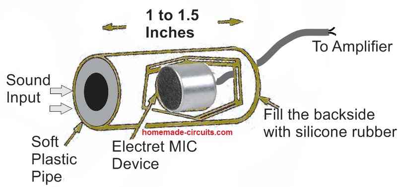
The microphone element is enclosed in a 1 to 1/2 inch length of lightweight plastic pipe, having silicone rubber filling the region behind the microphone.

The precise sizes are unimportant. The objective is to provide certain amount of directivity to the front of the microphone while isolating the rear.

Let's investigate a basic amplifier circuit now that we have a working pick-up device.

Circuit Description

The LM386 IC op-amp is still as good now as it was when it originally appeared several decades ago, and it is used in our first amplifier circuit in Fig. 2 below.
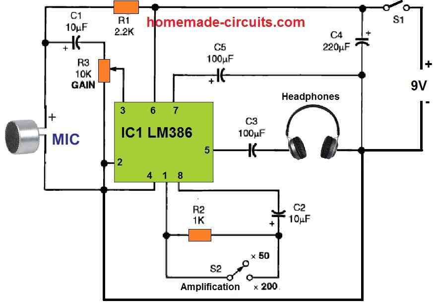
A section of shielded microphone wire connects the electret to the amplifier circuit. Make the cable length as little as feasible in case the microphone is used outdoors with the amplifier indoors.

The input of the amplifier is identical to that of an op-amp, comprising inverting and non-inverting inputs, a single output optimized to operate low impedance loads, and a gain adjust function.

Either inputs could be linked to circuit ground, resulting in a ground-referenced input. The amp operates on a 4 to 12 volt power supply and uses just under 30 mWs when not in use.

The maximal dissipation of the device is 660 mW. The only piece of advise I have for the amplifier's architecture is to keep the component lines short and the output wiring and components isolated from the input.

When utilizing S2's high gain level, carelessness would only produce creaks and squeaks. It's not easy to cope with, so try your best.

Sidenote: The above circuit can be also applied as a sensitive hearing aid circuit
You'll also like:

  • delay line block diagramAudio Delay Line Circuit – For Echo, Reverb Effects
  • index10 Stage Sequential Latch Switch Circuit Diagram
  • 6 watt Audio Amplifier Circuit Using TDA1011
  • FET 144 MHz converter compressedRF Amplifier Circuits and RF Converters

Filed Under: Audio and Amplifier Projects Tagged With: Insects, Listen, Wildlife

About Swagatam

I am an electronics engineer and doing practical hands-on work from more than 15 years now. Building real circuits, testing them and also making PCB layouts by myself. I really love doing all these things like inventing something new, designing electronics and also helping other people like hobby guys who want to make their own cool circuits at home.

And that is the main reason why I started this website homemade-circuits.com, to share different types of circuit ideas..

If you are having any kind of doubt or question related to circuits then just write down your question in the comment box below, I am like always checking, so I guarantee I will reply you for sure!

Previous Post: « Different Types of UPS systems – Explained
Next Post: Monitoring 220V AC Load Current using Current Transformer [Circuit Diagram] »

Reader Interactions

Questions & Answers

Total Posts: 2
Newest Oldest
Michael Buckingham
April 27, 2022 • 4 years ago #119707

An outdoor event here (British Columbia) had a board made up that has 8 bird sounds and the kid has to hit the right button to identify the correct name with the sound.
I don’t know what this circuit is called, hopefully there is a chip that can do this. I would love to make one for our organisation events (keeps.org)
your thoughts please, thank you, Michael Buckingham

Reply
SwagatamAdmin
April 28, 2022 • 4 years ago #119721

Sounds very interesting. I will try to look for the chip, if I happen to find it, will update the circuit design here for you!

Reply

Need Help? Please Leave a Comment! We value your input—Kindly keep it relevant to the above topic! Cancel reply

Your email address will not be published. Required fields are marked *

Primary Sidebar

My YouTube Channel

Circuit Simulator: Draw and Simulate Schematics

circuit simulator image

Categories

  • Arduino Projects (95)
  • Audio and Amplifier Projects (134)
  • Automation Projects (18)
  • Automobile Electronics (104)
  • Battery Charger Circuits (90)
  • Datasheets and Components (109)
  • Electronics Theory (151)
  • Energy from Magnets and Earth (43)
  • Games and Sports Projects (11)
  • Grid and 3-Phase (20)
  • Health related Projects (27)
  • Home Electrical Circuits (13)
  • Indicator Circuits (16)
  • Inverter Circuits (98)
  • Lamps and Lights (161)
  • Meters and Testers (72)
  • Mini Projects (28)
  • Motor Controller (68)
  • Oscillator Circuits (30)
  • Pets and Pests (15)
  • Power Supply Circuits (91)
  • Remote Control Circuits (50)
  • Security and Alarm (65)
  • Sensors and Detectors (107)
  • SMPS and Converters (46)
  • Solar Controller Circuits (62)
  • Temperature Controllers (44)
  • Timer and Delay Relay (51)
  • Voltage Control and Protection (44)
  • Water Controller (37)
  • Wireless Circuits (31)

Subscribe to get New Circuits in your Email

Other Links

  • Privacy Policy
  • Cookie Policy
  • Disclaimer
  • Copyright
  • Videos
  • Sitemap

People also Search

555 Circuits | 741 Circuits | LM324 Circuits | LM338 Circuits | 4017 Circuits | Ultrasonic Projects | SMPS Projects | Christmas Projects | MOSFETs | Radio Circuits | Laser Circuits | PIR Projects |

Recent Comments

  • Swagatam on Electronic Circuit Projects, Tutorials, and Practical Engineering Solutions
  • Swagatam on Simplest Full Bridge Inverter Circuit
  • Amal on Simplest Full Bridge Inverter Circuit
  • Michael on Electronic Circuit Projects, Tutorials, and Practical Engineering Solutions
  • Swagatam on Electronic Circuit Projects, Tutorials, and Practical Engineering Solutions

Social Profiles

  • Twitter
  • YouTube
  • Instagram
  • Pinterest
  • My Facebook-Page
  • Stack Exchange
  • Linkedin

Calculators

  • ZVS Induction Heater + Tank Calculator Tool
  • Zener Diode Calculator
  • Wire Current and Thickness Calculator (Ampacity Calculator)
  • Voltage Divider Calculator
  • Transistor Base Resistor Calculator
  • Transistor Astable Multivibrator Calculator
  • TL431 Calculator
  • Solar Panel, Inverter, Battery Calculator
  • Ferrite Core Air Gap Calculator Tool
  • Parallel MOSFET Calculator Tool: How to Connect MOSFETs in Parallel Safely
  • LC Resonance Calculator for EV Battery Charger Circuits
  • LED String Series Resistor Calculator
  • PFC (Power Factor Correction) Calculator Tool: 3kW
  • Passive Power Factor Correction (PFC) Calculator
  • LM567 IC Calculator Tool
  • SMPS Flyback Boost Converter Calculator
  • Shunt Resistor Calculator for Ammeters
  • SCR and Triac Gate Resistor Calculator
  • Battery Back up Time Calculator
  • Boost Converter Calculator (Non-Isolated)
  • Bootstrap Capacitor Calculator
  • Buck Converter Calculator
  • Buck-Boost Converter Calculator
  • Capacitance Reactance Calculator
  • DCM Flyback Transformer & Wire Gauge Wire Size Calculator Tool
  • Filter Capacitor Calculator
  • IC 4047 Calculator (Frequency and PWM)
  • IC 4060 Calculator
  • IC 555 Astable Calculator
  • IC 555 Monostable Calculator
  • IC SG3525, SG3524 Calculator
  • Inductance Calculator
  • Induction Heater Inductor and Resonant Frequency Calculator
  • Induction Heater Work Coil Calculator
  • Inverter LC Filter Calculator
  • LC Resonance Calculator
  • LED Current Calculator
  • LM317, LM338, LM396 Calculator
  • NAND/NOT Gate RC Values Calculator
  • NOT, NAND Gate Frequency Calculator
  • Notch Filter Calculator Tool
  • Ohm’s Law Calculator
  • Phase Angle Phase Shift Calculator
  • Power Factor (PF) Calculator
  • RC Filter Calculator
  • Reactance Calculator
  • Sine Table Calculator for SPWM Arduino Code
  • Small Signal Transistor(BJT) and Diode Quick Datasheet
  • SMPS Calculator for Toroidal Ferrite Transformers
  • SMPS Flyback Transformer Calculator – Design by Target Duty Cycle
  • TL431 Calculator
  • Op-Amp Hysteresis Resistor Calculator

© 2026 · Swagatam Innovations